42GR ATM Air Treatment Module - Carrier
42GR ATM Air Treatment Module - Carrier
42GR ATM Air Treatment Module - Carrier

Create successful ePaper yourself
Turn your PDF publications into a flip-book with our unique Google optimized e-Paper software.
9 - Water FLoW controL VaLVes<br />
9.1 - electrothermal actuator (on/off)<br />
This on/off type actuator is used with a <strong>Carrier</strong> room<br />
thermostat (electromechanical controller) and the <strong>Carrier</strong><br />
numeric controller.<br />
NOTE: The electrothermal actuator is delivered in the<br />
normally closed position regardless of the two-way or<br />
three-way valve body used (way A-AB closed in the case<br />
of a three-way valve).<br />
Therefore to enable the installation to be filled with water,<br />
the water circuits to be equalised and the units to be purged,<br />
the valves will have to be opened by sending a command<br />
from the wall thermostats.<br />
9.2 - replacing actuators<br />
The actuators on both the chilled water and the hot water<br />
valves may be replaced if either develops a fault.<br />
• Disconnect the power supply to the unit before carrying<br />
out any work on a unit.<br />
• Disconnect the actuator power supply cable.<br />
- On/off type actuator used with a <strong>Carrier</strong> numeric<br />
controller:<br />
Disconnect the quick connect power supply cable<br />
on the actuator.<br />
- On/off actuator used with a wall-mounted<br />
thermostat:<br />
Remove the plastic protection cap (held in place<br />
with two hexagon head (8 mm AF) screws).<br />
Disconnect the quick connect power supply cable<br />
on the actuator. This can be done by using a screwdriver<br />
to press down on the spring tongue and<br />
pulling out the wire from the appropriate terminal.<br />
• Uncouple the faulty actuator. Reverse the removal<br />
procedure described above when installing the replacement<br />
motor.<br />
WARNING: Ensure that the actuator is firmly screwed to<br />
the valve body (maximum torque 15 N·m).<br />
22<br />
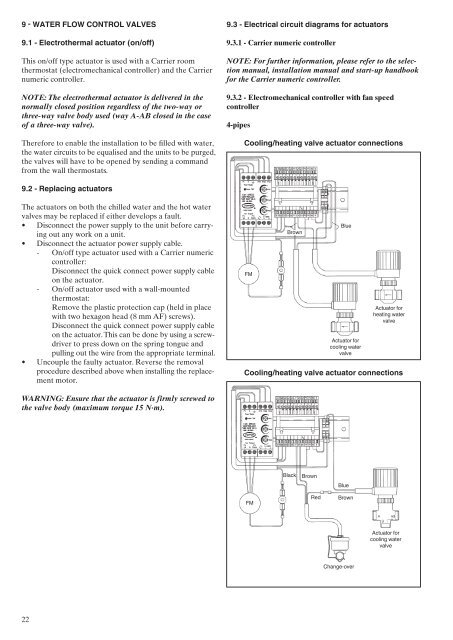
9.3 - electrical circuit diagrams for actuators<br />
9.3.1 - <strong>Carrier</strong> numeric controller<br />
NOTE: For further information, please refer to the selection<br />
manual, installation manual and start-up handbook<br />
for the <strong>Carrier</strong> numeric controller.<br />
9.3.2 - electromechanical controller with fan speed<br />
controller<br />
4-pipes<br />
cooling/heating valve actuator connections<br />
FM<br />
FM<br />
Brown<br />
Black<br />
Brown<br />
Blue<br />
Actuator for<br />
cooling water<br />
valve<br />
Blue<br />
Red Brown<br />
Change-over<br />
Actuator for<br />
heating water<br />
valve<br />
cooling/heating valve actuator connections<br />
Actuator for<br />
cooling water<br />
valve