Alco Controls
Alco Controls
Alco Controls

Create successful ePaper yourself
Turn your PDF publications into a flip-book with our unique Google optimized e-Paper software.
12<br />
<strong>Alco</strong> <strong>Controls</strong><br />
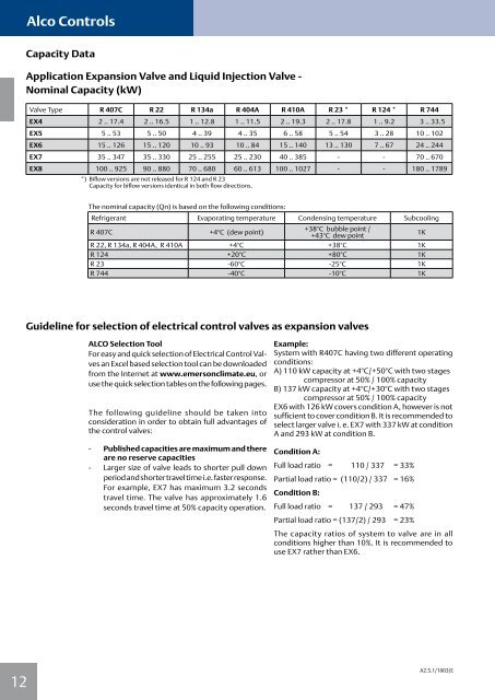
Capacity Data<br />
Application Expansion Valve and Liquid Injection Valve -<br />
Nominal Capacity (kW)<br />
Valve Type R 407C R 22 R 134a R 404A R 410A R 23 * R 124 * R 744<br />
EX4 2 .. 17.4 2 .. 16.5 1 .. 12.8 1 .. 11.5 2 .. 19.3 2 .. 17.8 1 .. 9.2 3 .. 33.5<br />
EX5 5 .. 53 5 .. 50 4 .. 39 4 .. 35 6 .. 58 5 .. 54 3 .. 28 10 .. 102<br />
EX6 15 .. 126 15 .. 120 10 .. 93 10 .. 84 15 .. 140 13 .. 130 7 .. 67 24 .. 244<br />
EX7 35 .. 347 35 .. 330 25 .. 255 25 .. 230 40 .. 385 - - 70 .. 670<br />
EX8 100 .. 925 90 .. 880 70 .. 680 60 .. 613 100 .. 1027 - - 180 .. 1789<br />
*) Biflow versions are not released for R 124 and R 23<br />
Capacity for biflow versions identical in both flow directions.<br />
The nominal capacity (Qn) is based on the following conditions:<br />
Refrigerant Evaporating temperature Condensing temperature Subcooling<br />
R 407C +4°C (dew point)<br />
+38°C bubble point /<br />
+43°C dew point<br />
1K<br />
R 22, R 134a, R 404A, R 410A +4°C +38°C 1K<br />
R 124 +20°C +80°C 1K<br />
R 23 -60°C -25°C 1K<br />
R 744 -40°C -10°C 1K<br />
Guideline for selection of electrical control valves as expansion valves<br />
ALCO Selection Tool<br />
For easy and quick selection of Electrical Control Valves<br />
an Excel based selection tool can be downloaded<br />
from the Internet at www.emersonclimate.eu, or<br />
use the quick selection tables on the following pages.<br />
The following guideline should be taken into<br />
consideration in order to obtain full advantages of<br />
the control valves:<br />
- Published capacities are maximum and there<br />
are no reserve capacities<br />
- Larger size of valve leads to shorter pull down<br />
periodandshortertraveltimei.e.fasterresponse.<br />
For example, EX7 has maximum 3.2 seconds<br />
travel time. The valve has approximately 1.6<br />
seconds travel time at 50% capacity operation.<br />
Example:<br />
System with R407C having two different operating<br />
conditions:<br />
A) 110 kW capacity at +4°C/+50°C with two stages<br />
compressor at 50% / 100% capacity<br />
B) 137 kW capacity at +4°C/+30°C with two stages<br />
compressor at 50% / 100% capacity<br />
EX6 with 126 kW covers condition A, however is not<br />
sufficient to cover condition B. It is recommended to<br />
select larger valve i. e. EX7 with 337 kW at condition<br />
A and 293 kW at condition B.<br />
Condition A:<br />
Full load ratio = 110 / 337 = 33%<br />
Partial load ratio = (110/2) / 337<br />
Condition B:<br />
= 16%<br />
Full load ratio = 137 / 293 = 47%<br />
Partial load ratio = (137/2) / 293 = 23%<br />
The capacity ratios of system to valve are in all<br />
conditions higher than 10%. It is recommended to<br />
use EX7 rather than EX6.<br />
A2.5.1/1003/E