Alco Controls
Alco Controls
Alco Controls

Create successful ePaper yourself
Turn your PDF publications into a flip-book with our unique Google optimized e-Paper software.
144<br />
<strong>Alco</strong> <strong>Controls</strong><br />
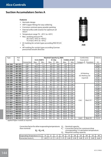
Suction Accumulators Series A<br />
Features<br />
• Hermetic design<br />
• ODF Copper fittings for easy soldering<br />
• Corrosion resistant epoxy powder painting<br />
• Internal orifice with strainer for optimum oil<br />
return<br />
• Temperature range TS: -45°C to +65°C<br />
• Max. working pressure PS:<br />
20.7 bar (-10°C to +65°C)<br />
15.5 bar (-45°C to -10°C)<br />
• CE marking for certain types according PED 97/23<br />
EC<br />
• HP marking for certain types according German<br />
pressurised vessels directive<br />
Type Part Nominal Capacity Q (kW) n Conformitiy Volume<br />
No. R 22 / R407C R 134a R 404A / R 507 Assessment<br />
Connection Max. Min. Max. Min. Max. Min. Category Procedure Lit.<br />
A08-304 001 973 1/2“ 7,0 1,1 4,2 0,6 4,6 0,7 0,73<br />
A10-305 001 977 5/8“ 10,5 1,6 6,0 0,9 7,0 1,1 0,93<br />
A12-305 001 978 5/8“ 10,5 1,6 6,0 0,9 7,0 1,1 1,16<br />
A12-306 001 979 3/4“ 14,0 2,1 8,1 1,2 9,1 1,4 1,16<br />
A14-305 001 980 5/8“ 10,5 1,6 6,0 0,9 7,0 1,1 HP Marking 1,40<br />
A14-306 001 987 3/4“ 14,0 2,1 8,1 1,2 9,1 1,4 (CE Marking not 1,40<br />
A06-405 001 989 5/8“ 10,5 1,6 6,0 0,9 7,0 1,1 required) 0,93<br />
A10-405 001 990 5/8“ 10,5 1,6 6,0 0,9 7,0 1,1 1,75<br />
A10-406 001 994 3/4“ 14,0 2,1 8,1 1,2 9,1 1,4 1,75<br />
A09-506 881 995 3/4“ 14,0 2,1 8,1 1,2 9,1 1,4 2,33<br />
A09-507 882 455 7/8“ 25,6 3,8 14,0 2,1 16,1 2,4 2,33<br />
A12-506 881 996 3/4“ 14,0 2,1 8,1 1,2 9,1 1,4 3,29<br />
A12-507 881 998 7/8“ 25,6 3,8 14,0 2,1 16,1 2,4 3,29<br />
A13-507 882 007 7/8“ 25,6 3,8 14,0 2,1 16,1 2,4 3,80<br />
A13-509 882 011 1-1/8“ 41,4 6,2 25,3 3,8 26,7 4,0 3,80<br />
A17-509 882 012 1-1/8“ 41,4 6,2 25,3 3,8 26,7 4,0 4,87<br />
A17-511 882 013 1-3/8“ 66,0 9,9 37,6 5,6 42,8 6,4 Cat.I Mod. D1* 4,87<br />
A11-607 882 014 7/8“ 25,6 3,8 14,0 2,1 16,1 2,4 4,30<br />
A13-607 882 015 7/8“ 25,6 3,8 14,0 2,1 16,1 2,4 4,98<br />
A13-609 882 019 1-1/8“ 41,4 6,2 25,3 3,8 26,7 4,0 4,98<br />
A14-611 882 020 1-3/8“ 66,0 9,9 37,6 5,6 42,8 6,4 5,48<br />
A17-613 882 022 1-5/8“ 100,0 15,0 59,7 9,0 63,9 9,6 6,85<br />
A17-642 889 023 42 mm 100,0 15,0 59,7 9,0 63,9 9,6 6,85<br />
A20-613 882 021 1-5/8“ 100,0 15,0 59,7 9,0 63,9 9,6 8,21<br />
A25-613 882 023 1-5/8“ 100,0 15,0 59,7 9,0 63,9 9,6 Cat.II Mod. D1 10,23<br />
* applied higher module as required.<br />
Correction factor for other evaporating temperatures<br />
than nominal:<br />
Q n = Q o x K t<br />
A08<br />
Q n : Nominal capacity<br />
K t : Correction factor for a pressure drop<br />
corresponding 1 K saturation temperature<br />
Q o : Required cooling capacity<br />
Evaporating Temperature (°C) +4 0 -5 -10 -15 -20 -25 -30 -35 -40<br />
Correction Factor Ks 1,00 1,12 1,35 1,75 2,00 2,50 3,00 3,75 5,00 6,60<br />
A2.5.1/1003/E