
Create successful ePaper yourself
Turn your PDF publications into a flip-book with our unique Google optimized e-Paper software.
The Pennsylvania State University<br />
The Graduate School<br />
Department of Nuclear Engineering<br />
A Study of Load Change Control in PWRs<br />
Using the Methods of Linear Optimal Control<br />
A Thesis in<br />
Nuclear Engineering<br />
by<br />
Ting Yang<br />
Doctor of Philosophy<br />
March 1983
o<br />
6<br />
The Pennsylvania State University<br />
The Graduate School<br />
Department of Nuclear Engineering<br />
A Study of Load Change Control in PWRs<br />
Using the Methods of Linear Optimal Control<br />
A Thesis in<br />
Nuclear Engineering<br />
by<br />
Ting Yang<br />
Submitted in Partial. Fulfi1Iment<br />
of the Requirements<br />
for the Degree of<br />
Doctor of Philosophy<br />
March 1983<br />
I grant The Pennsylvania State University the nonexclusive<br />
right to use this work for the University's own purposes and<br />
to make single copies of the work available to the public on<br />
a not-for-profit basis if copies are not otherwise available.<br />
Ting Yang
We approve the thesis of Ting Yang.<br />
Date of Signature:<br />
1/<br />
V<br />
2y. )^?Z<br />
Edward S. Kenney, Prdfessor of|<br />
Nuclear Engineering, Chairman of<br />
Committee, Thesis Adviset; y<br />
Edward H. Klevans, Professor of<br />
Nuclear Engineering, Member of<br />
Doctoral Committee<br />
Anthony H. Foderaro, Professor of<br />
Nuclear Engineering, Member of<br />
Doctoral Committee<br />
Oohnyfe. Lewis, Professor of<br />
Electrical Engineering, Member of<br />
D'octoral Committee<br />
ii
ABSTRACT<br />
This thesis investigates the application of modern<br />
control theory to the problem of controlling load changes<br />
in PWR power plants, A linear optimal state feedback<br />
scheme resulting from linear optimal control theory with<br />
a quadratic cost function is reduced to a partially<br />
decentralized control system using "mode preservation"<br />
techniques. Minimum information transfer among major<br />
components of the plant is investigated to provide an<br />
adequate coordination, simple implementation, and a<br />
reliable control system. ^<br />
Two control approaches are proposed: servo and<br />
model following. Each design considers several<br />
information structures for performance comparison.<br />
Integrated output error has been included in the control<br />
systems to accommodate external and plant parameter<br />
disturbances. In addition, the "cross limit" feature,<br />
specific to certain modern reactor control systems, is<br />
considered in the study to prevent low pressure reactor<br />
trip conditions.<br />
An n^*^ order nonlinear model for the reactor and<br />
boiler is derived based on theoretical principles, and<br />
simulation tests are performed for 10% load change as an<br />
illustration of system performance.<br />
JNSTITUTO OE PE SOU<br />
ill
TABLE OF CONTENTS<br />
Page<br />
ABSTRACT iii<br />
LIST. OF TABLES v<br />
LIST OF FIGURES .... vi<br />
ACKNOWLEDGMENTS vii<br />
I. INTRODUCTION<br />
1.1 - Control Needs and Requirements 1<br />
1.2 - Objective 5<br />
1.3 - PWR Nuclear Power Plant<br />
1.3.1 - Plant Dynamics and Modeling ...... 7<br />
1.3.2 - Current Control System Design .... 24<br />
1.4 - Literature Review 29<br />
II. CONTROL SYSTEM DESIGN METHODS<br />
11.1 - General Considerations 34<br />
11.2 - Optimal Linear Quadratic Problem<br />
11.2.1 - Conventional Regulator Problem.. 36<br />
11.2.2 - External Disturbances 40<br />
11.2.3 - Set Point Changes and Servo<br />
Problems ^ 44<br />
11.2.4 - Model Following Control System.. 54<br />
11.3 - Related Issues on Hierarchical and<br />
Decentralized Control ....... 60<br />
11.4 - Control Structure Constraints ... 63<br />
III. A PWR CONTROL SYSTEM DESIGN<br />
III.1 - Control Problem Formulation and General<br />
Considerations 78<br />
"111.2 - Step Command Input Control System-Design 81<br />
III.3 - Model Following Control System Design... 88<br />
IV. PLANT SIMULATION: RESPONSES AND COMPARISONS 92<br />
V. SUMMARY AND CONCLUSIONS 107<br />
APPENDIX A - PSEUDO INVERSE Ill<br />
REFERENCES 115<br />
IV
LIST OF TABLES<br />
Table Page<br />
1.1 Numerical Values of Plant Parameters and<br />
Constants 21<br />
1.2 Numerical Values of the Linear Systems<br />
Coefficients .. 23<br />
111.1 System Poles 84<br />
111.2 Feedback Gains for the Servo Problem 86<br />
111.3 Matrix W Used (Diagonal Elements) 86<br />
111.4 Model System Coefficients 88<br />
111.5 Feedback Gains for the Model Following Control<br />
System 90<br />
IV.1 Control Systems Case-Coded for Each<br />
Information Structure . 93<br />
,N8T,TUTO Oe PESOU P.S . • - ^^'^ ^ ^ "y^' ' ^^^^^
LIST OF FIGURES<br />
Figure Page<br />
1.1 The PWR Diagram 8<br />
1.2 Recirculation Type of Steam Generator ........ 14<br />
1.3 Conventional Reactor Control System 26<br />
1.4 Conventional Steam Generator Water Level<br />
Control System 28<br />
11.1 Servo Control System Diagram 50<br />
11.2 Control Structure Constraints 64<br />
111.1 Coolant Average Temperature Program 79<br />
111.2 The Servo Control System Diagram 86<br />
111.3 Model Following Control System Diagram 91<br />
IV.1 Several Information Structures for Servo<br />
Control System — 94<br />
IV.2 Control System Based on Decentralized Design.. 96<br />
IV.3 Several Information Structures for Model<br />
Following Control System 98<br />
IV.4 Cross Limit Effect 99<br />
IV.5 Moderator Temperature Coefficient Disturbed<br />
for CASE I.A . 101<br />
IV.6 Moderator Temperature Coefficient Disturbed<br />
for CASE II.A ., 102<br />
IV.7 Moderator Temperature Coefficient Disturbed<br />
for CASE I.C 103<br />
IV.8 Moderator Temperature Coefficient Disturbed<br />
for CASE II.C 104<br />
IV.9 CASES I.C and II.c Subject to External<br />
Disturbance 106<br />
IN9T1TUTO 0^ '<br />
1<br />
VI
ACKNOWLEDGMENTS<br />
The author wishes to express his thanks to Dr.<br />
Edward S. Kenney for his advice and encouragement<br />
throughout his graduate education, and to Dr. John B.<br />
Lewis for his assistance during the course of this<br />
research at The Pennsylvania State University.<br />
The author also wishes to thank his wife Tereza<br />
for her typing and continued interest in the progress<br />
of this thesis.<br />
VI 1
CHAPTER I<br />
INTRODUCTION<br />
1.1 - Control Needs and Requirements<br />
The primary control objective of a nuclear power plant<br />
follows from two basic conflicting requirements. The power<br />
industry demands that the unit be able to handle substantial<br />
power transients in order to prevent contingent network<br />
instability caused by load variation during normal network<br />
operating conditions. On the other hand, a nuclear power<br />
plant must operate within severe constraints on the range<br />
of safe operating conditions.<br />
A power plant can operate safely if the operating<br />
conditions are maintained within the limitations of its<br />
components. In the reactor, the cladding is the most<br />
susceptible component to damage in the event of departure<br />
from nucleate boiling (DNB.) caused by a localized high<br />
heat flux. Such an uneven power distribution is more likely<br />
to occur during power transients, since the control rods<br />
are moved from their steady state positions to accommodate<br />
the load change. The operating condition of a steam<br />
generator is usually limited by thermal constraints such as<br />
rapid temperature change or sharp temperature deviations<br />
JNSTITUIO D£ PFSOU ' '-i f •'
along its structure. Thermal stress is also the most common<br />
cause of turbine damage. Such stresses can be reduced by<br />
providing slower changes in steam temperature or by<br />
keeping the temperature changes small.<br />
With the increasing cost of alternative energy sources,<br />
nuclear energy has been shown to be one Of the most<br />
competitive energy sources. Therefore, because they are<br />
usually the cheapest source of electricity, it is usual to<br />
operate nuclear power plants at full power all the time.<br />
Such use is referred to as "base loaded operation;" a mode<br />
of operation which leaves the other more expensive sources<br />
of power to handle the load balance in the network during<br />
daily load variations.<br />
Although it is reasonable that most of the nuclear<br />
power plants operate as base load units, it is still<br />
strongly recommended that vendors incorporate into a nuclear<br />
power plant's design a load following or maneuvering<br />
capability to provide aid in restoring network stability<br />
caused by unscheduled outages. The problem is more severe<br />
if the nuclear generated power contributes a significant<br />
fraction of the overall power in the network.<br />
Some areas of the world may have large hydroelectric<br />
supplies. This results in an inversion of the cost picture<br />
and reinforces the reason for introducing load following<br />
capability. In such cases, hydroelectric is usually the<br />
cheapest source of power and, of course, requires power
operation maneuverability from reactor plants.<br />
Typically, the nominal response rate of a current<br />
nuclear power plant is about 10% of rated output per minute.<br />
However, the reactor system suffers gradual changes in the<br />
plant parameters with time such as fuel burnup, temperature<br />
coefficient, rod worth, residue buildup in ducts and pipes,<br />
fission poisoning products,etc.. Some of these effects can<br />
be compensated for by using controllable boron concentration<br />
in thé reactor coolant. These variations generally degrade<br />
the plant performance, requiring periodic tuning processes.<br />
However, in practice, these situations are often tolerated<br />
rather than made subject to complex and costly tuning<br />
procedures [1], and sometimes the operator is not sure<br />
whether the reactor will be capable of following a<br />
specific load schedule [2].<br />
Plant performance deterioration may lead to safety-<br />
related problems because diversified transients for nearly<br />
identical load changes are more likely to cause operator<br />
confusion than are standardized transients during normal<br />
operating conditions. There may also be external effects<br />
because during a sizeable load variation in the network,<br />
poor reactor behavior would require other plants to<br />
compensate for this poor response in order to restore the<br />
network stabi1ity.<br />
Another area that needs improvement is related to the<br />
methodologies used to design the control system. A power
plant's dynamics consist of interactive processes among<br />
several components in the plant; therefore, an appropriate<br />
coordination action is necessary. Although some modern<br />
control system designs currently used in existing nuclear<br />
power plants incorporate coordination features, they<br />
represent the applied state-of-the-art evolved from<br />
classical control techniques based on single input, single<br />
output methods [3]. Therefore, a systematic and multivari-<br />
able design approach is highly desirable.<br />
On the other hand, safety-related issues suggest<br />
decentralization of the control system. The concept is in<br />
contrast to the common practice on "Candu" Canadian Power<br />
Plants [4]. Such a decentralized control concept reduces<br />
the interdependence of the localized control systems and<br />
the consequence of the occurrence of a sensor failure.<br />
There is also an expected reduction in the overall system<br />
implementation cost. However, due to the interactive<br />
process among system components, some information exchanges<br />
are necessary in order to coordinate the components to<br />
provide a smooth and rapid transient response during load<br />
changes.<br />
In view of the last two conflicting issues, a<br />
minimization of the information exchange necessary for a<br />
satisfactory plant operation is required.<br />
In summary, one can write the primary control<br />
objectives of a nuclear power plant control system in the
form of the following needs:<br />
1. Adequate load following capability;<br />
2. Ability to control transients so that components<br />
operate only within safe operating limits;<br />
3. Provide for "self tuning" of the control system;<br />
4. Achieve "robustness" in the sense of accommodating<br />
external disturbances, parameter variations, and<br />
localized sensor and controller failures;<br />
5. Multivariable and systematic approach for optimal<br />
coordination among the components;<br />
6. Use of a partially decentralized control system<br />
with minimum required information exchange;<br />
7. Reduce cost consistent with the above objectives.<br />
1.2 - Objective<br />
In view of the increasing requirement for improved<br />
control systems for nuclear power plants, it is the<br />
objective in this thesis to investigate the applicability<br />
of modern control theory to the design of such control<br />
systems. This work is directed towards problems of load<br />
changes in PWR plants using linear optimal control<br />
quadratic functions.<br />
Current control systems are designed using single<br />
input, single output classical control methods. However,
due to the multi-input, multi-output characteristics of a<br />
nuclear plant, the overall control system is designed<br />
separately for each major component of the plant. The<br />
interactions among these components are either ignored or<br />
are incorporated into the system based on the experience<br />
of the designer, making the process essentially a "state-<br />
of-the-art" design approach. The advantage of using<br />
multivariable design methods is that adequate coordination<br />
schemes are generated as a direct result of the method.<br />
The overall design problem considers the following<br />
objectives: the ability of the control system to maintain<br />
adequate performance when the plant is subjected to<br />
parameter variations and external disturbances; and, the<br />
retention of the simplicity of the resulting control<br />
system in its final implementation.<br />
For the simple control systems considered in this<br />
thesis, a requirement for the minimum information transfer<br />
among major components of the plant is considered and the<br />
usual required observers are avoided by using mode<br />
preservation techniques. Two control systems are proposed:<br />
the first approach is a servo control scheme and the<br />
second is based upon the idea of model reference control.<br />
The model reference approach is intended to increase<br />
robustness of the control system when it is subjected to<br />
disturbances. Moreover, such a system will attempt to<br />
standardize all transients despite the change of parameters<br />
IN8TITUTO.DE PESQU'S*S E^ERGr. ' i<br />
C» S E NUCLE ^''-^ES<br />
I.' P, £, N.<br />
— — • —
occurring during the core life.<br />
1.3 - PWR Nuclear Power Plant<br />
1.3.1 - Plant Dynamics and Modeling<br />
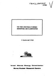
A pressurized water reactor power plant consists,<br />
essentially, of two loops as shown in Figure 1.1. The<br />
pressurized water coolant in the primary loop carries the<br />
heat energy produced in the reactor to the steam generator<br />
where the heat is transferred to the secondary loop by<br />
generating an adequate amount of steam to the turbine which<br />
in turn, produces shaft power from the expansion of the<br />
steam. Finally, the shaft drives the generator to produce<br />
the required electric power.<br />
The heat source in a nuclear power plant, as is well<br />
known, originates as the energy released in the nuclear<br />
fission chain reaction. Since the nuclear power is<br />
proportional to the neutron density, a specific power level<br />
is maintained when the total absorption and leakage rate is<br />
equal to the neutron production rate from the fission<br />
process. A measurement of such a balance or unbalance, can<br />
be expressed in terms of a quantity called reactivity.<br />
There are several factors which can affect the reactivity<br />
value such as the choice of structural components, fuel
\ ^ nprãf<br />
PRESSURIZE R I Z E í A ^<br />
Control Rods<br />
CORE<br />
Heate<br />
Hot Leg<br />
Cold Leg<br />
PRIMARY L(OP<br />
STEAM<br />
GENERA<br />
TOR<br />
Steam<br />
Throttle Valve<br />
SECONDARY LOOP<br />
Feedwater<br />
¿ZiValve<br />
Feedwater ^-^<br />
Figure 1.1 - PWR Diagram<br />
composition, absorbing control rods, fission products,<br />
CONDEN<br />
SER<br />
inherent temperature feedback, etc.. Among these items, for<br />
control purposes, it is important to distinguish between<br />
those which are uncontrollable and those which can be<br />
voluntarily manipulated. Current practice uses control rod<br />
positioning in conduction with the variable concentration<br />
of dissolved boric acid in the coolant to provide the<br />
desired reactivity control. Because varying boric acid<br />
concentration is a very slow dynamic process, it is used<br />
to compensate for slowly varying parameters like fission<br />
product buildup, xenon poisoning, fuel depletion, and<br />
others, leaving the control rods to compensate those<br />
varying parameters which cause fast reactivity changes<br />
8<br />
River
like sudden changes in temperature during load variations.<br />
The energy of fission is mostly dissipated within the<br />
fuel, and a small fraction is deposited in the coolant and<br />
other structural materials. In a PWR, the primary coolant<br />
is maintained at approximately 2200 psia.by a pressurizer,<br />
in order to insure safe operating conditions. Pumped from<br />
the cold leg, the coolant is heated primarily by convection<br />
during its passage through the core.<br />
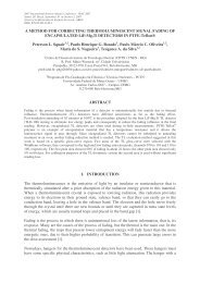
A common boiler currently used in PWR plants is the<br />
recirculation type of steam generator. Here, the hot<br />
primary coolant enters the steam generator at the bottom<br />
and flows through a bundle of inverted U-type tubes. On<br />
the secondary loop side, the feedwater mixes with the<br />
recirculation flow at a lower pressure, and passes<br />
through the riser section where part of it is heated and<br />
part is evaporated. The steam-water mixture is then taken<br />
to the moisture separators and only dried steam is sent<br />
to the turbine.<br />
The amount of steam sent to the turbine is controlled<br />
by a throttle valve which also provides control of the<br />
pressure in the steam generator. Because of reactor<br />
response time limitations, a by-pass valve is used to<br />
compensate for excessive production of steam during load<br />
reductions.<br />
A simplified model of a PWR plant will now be<br />
considered and its linearized form will be used for
subsequent control design examples. Note that, for control<br />
design in state variable formulation, it is convenient and<br />
practical to utilize a simple, but accurate model, rather<br />
than a detailed one, since the complexity of the resulting<br />
controller is proportional to that of the model.<br />
1.3.1.1 - The Primary Loop Model. Assuming a point<br />
reactor kinetic model and an averaged group of delayed<br />
neutrons, the neutron density and the precursor<br />
concentration can be expressed as the following [5]:<br />
_dP_ = J L ^ p{t) + AC(t) / (1.1.a)<br />
_dC_ _ _ß_ p(t) . AC(t) (I.l.b)<br />
where P is the reactor power, and for "lumped" reactor it<br />
is proportional to the neutron density [MW];<br />
C is the spatial average precursor concentration<br />
expressed in energy units [MW];<br />
^ is the reactivity;<br />
f3 is the delayed neutron fraction;<br />
A is the effective precursor decay constant [sec"^];<br />
and 1 is the mean generation time [sec].<br />
A typical value for 1 ranges from 10"^ to 10"^ seconds<br />
10
Such a small time constant leads to numerical difficulties<br />
in control simulation on digital computer. In general, the<br />
resulting controllers from a direct application of these<br />
equations are impracticable. Experience has shown that the<br />
fast mode can be neglected by setting<br />
dP<br />
= 0, a procedure<br />
"3r<br />
called "the prompt jump approximation." The reduced<br />
equations become<br />
and<br />
dC<br />
P =<br />
1 A<br />
AC<br />
If reactivity/a is expressed in dollar $ "Dnits, and P<br />
I<br />
I<br />
1<br />
j<br />
^, the equations can be rewritten<br />
i1 c<br />
11<br />
(1.2.a)<br />
(I.2.b)<br />
nal C divided by full power P„.<br />
1 o<br />
erent temperature feedback<br />
I external control in the reactivity.
-"C (Tf - Tfo' - T„„) (1.3)<br />
Where is the reactivity externally controlled using<br />
control rods;<br />
oC^ is the doppler reactivity coefficient ["F"^];<br />
oC^^ is the coolant reactivity coefficient ["F"^];<br />
reactivity.<br />
is the core average fuel temperature [*F];<br />
is the core average coolant temperature [°F];<br />
and T^^ are fixed values and the term<br />
+oC^ T^Q) is referred to as "power defect"<br />
Due to severe limitations on the speed of rod<br />
movement, it is more convenient to control t^e rod speed<br />
rather than its position, i.e..<br />
12<br />
= u^ (1.4)<br />
where is the differential rod reactivity worth [$/m];<br />
and Uj, is the rod speed [m/sec].<br />
The incorporation of a control delay mechanism can be<br />
approximated by a first order time lag:<br />
^ = ^ (u, - u,) {1.5)
where Tp is the control mechanism time constant [sec];<br />
and is the input signal.<br />
For one node fuel model, the fuel temperature variation<br />
can be expressed using the energy balance:<br />
or<br />
= "o TWT - *fw ^fw 'Tf - Tw)) . (1.6)<br />
where T.p is the fuel temperature ["F];<br />
M^jj is the mass of the fuel [Kg]; ^<br />
is the fuel specific heat [Joules/Kg °F];<br />
F^ is the fraction of power generated within the fuel;<br />
is the full power generation [MW];<br />
A^^ is the heat transfer area between the fuel and<br />
2<br />
coolant [m ];<br />
K^^ is the effective heat transfer coefficient between<br />
the fuel and coolant [Joules/m °F];<br />
T is the core average coolant temperature [°F].<br />
W<br />
The primary coolant temperature is divided into two<br />
nodes: average temperature and outlet temperature.<br />
-3r = % ^1 ^ l-Tp + '^fwl "^fw ^"^f - ''"w^ ~<br />
13<br />
WwV^^w-^wl^ ^'-'-'^
where M^^ and M^^2 ^re the total coolant mass in the lower<br />
and upper node, respectively in the core [Kg];<br />
C is the coolant specific heat [Joules/Kg "F];<br />
W<br />
F^^ and F^^2 ^"^^ "^^^ fractions of power generated<br />
within the correspondent node;<br />
A^^^ and A^^2 ^"^^ heat transfer area for<br />
correspondent node [m 3;<br />
is the coolant flow rate [Kg/sec];<br />
T^^ is the inlet coolant temperature [°F].<br />
1.3.1.2 - The Secondary Loop Model. Consider the<br />
following diagram, shown in Figure 1.2, for the steam<br />
generator:<br />
From REACTOR<br />
OUTLET<br />
To REACTOR<br />
INLET<br />
sat<br />
tw<br />
-sg-<br />
4 ^<br />
w<br />
_!? TURBINE<br />
FEEDWATER<br />
Figure 1.2 - Recirculation Type of Steam Generator.<br />
14
Based on energy balance, one can write:<br />
K -7u^ = W„ C„ (T. - T ) - A„„ K (T - T„) (I.8.a)<br />
p p dt p p ^ m p pm pm ^ p ni' \ v «/<br />
and<br />
"n, = V - T„) - V (T^ - Tp (I.8.b)<br />
Where Tp is the effective coolant temperature in the steam<br />
generator, corresponding to reactor inlet temperature<br />
[°F];<br />
Tj^ is the inlet temperature of the steam generator<br />
corresponding to reactor outlet temperature [T];<br />
is the temperature of the metal tube's [°F];<br />
Wp is the flow rate [Kg/sec];<br />
Apjjj is the total heat transfer area between the<br />
2<br />
coolant and the metal tubes [m ];<br />
Kpju is the effective heat transfer coefficient<br />
between the coolant and the metal tubes [Joules/m "F];<br />
Mjjj is the mass of tubes [Kg];<br />
Cjji is the specific heat of the metal tubes<br />
[Joules/Kg °F];<br />
^ms total heat transfer area between the<br />
metal tubes and secondary coolant [m ];<br />
Kji^g is the effective heat transfer coefficient between<br />
the metal tubes and secondary coolant [Joules/m ''F];<br />
T* is the saturated temperature correspondent to the<br />
15
pressure in steam generator ["F];<br />
Mp is the total coolant mass in the steam generator<br />
CKg].<br />
The mass balance gives:<br />
d M-<br />
d<br />
16<br />
- Wfw.- % (1.9-^)<br />
where is the mass of the fluid in the steam generator<br />
[Kg];. .<br />
[Kg];<br />
is the mass of the steam in the steam generator<br />
W^^ is the feedwater flow [Kg/sec];<br />
W^g is the steam production rate [Kg/sec];<br />
is the steam flowing out rate [Kg/sec].<br />
The volume balance gives:<br />
d V. d V d V^Q,<br />
where is the volume occupied by fluid in the steam<br />
generator;<br />
is the volume occupied by steam in the steam<br />
generator;<br />
INSTITUTO OE
VyQj is the total volume of the steam generator.<br />
For = v^ and = v^, using Equations I.9.a<br />
1.9.b, and 1.10, and assuming<br />
^ ^t ^ ^s ^^s ^ ''s<br />
we have the results:<br />
where v.^ is the specific volume of fluid [m^/Kg];<br />
Vg is the specific volume of steam [m'^AKg];<br />
and is the steam pressure [psia].<br />
The energy balance for the steam generator can be<br />
expressed as follows:<br />
d Uf Mf d u. d<br />
Where u^ and u^ express internal energy of fluid and<br />
steam, respectively;<br />
h^^^ is the feedwater enthalpy [Joules/Kg];<br />
h^Q is the steam enthalpy [Joules/Kg].<br />
P_ V<br />
But u = h -<br />
17
and, using the approximation<br />
there results:<br />
and<br />
dh ah t-ll<br />
d u^ ah. d P3<br />
-w" = ^^-FT' - T sr'<br />
s<br />
Substituting into 1.12, W^^ can be expressed as:<br />
ah. ah V P3 avg^<br />
where = ((^) - "T ^ + ^ ^aFr " T" " T" ^aFT^<br />
18<br />
(1.13)<br />
Substituting W^g into Equation 1.11, one obtains the<br />
following:<br />
* "a, -<br />
Where B^ = [m^ ( ( ^ - -f ) . ( ( ^ - ^ - ^ (^))]
or<br />
The steam flow W^^ can be expressed approximately in<br />
terms of throttle valve opening C^, by [6]:<br />
where is a constant<br />
"so = % ^ •<br />
The saturation temperature T* can be approximated as a<br />
linear function of pressure P :<br />
where T^ is a suitable constant.<br />
Furthermore, one may assume:<br />
s<br />
•^ms = "^ms •''^k ''s . (1.16)<br />
where K° andoC. are also suitable constants.<br />
iTI S K<br />
The water mass variation can be obtained by substituting<br />
Equations 1.13 and 1.14 into the fluid mass balance of<br />
Equation 1.9.a.<br />
19
y:<br />
ST- " Vf ^ - "so (1.17)<br />
The turbine valve opening dynamic can be approximated<br />
^ (u, -C;) (1.18)<br />
where is the valve positioning time constant [sec];<br />
and Uy is the valve opening input signal.<br />
It is also assumed that the valve positioning control<br />
provides an adequate turbine response, and it is, in fact,<br />
realizable by imposing certain values on the elements of<br />
the weighting matrices.<br />
The differential Equations 1.2.a, 1.4, 1.5, 1.6, 1.7.a,<br />
I.7.b, I.8.a, I.8.b, 1.14, 1.17 and 1.18, and the<br />
algebraic Equations I.2.b, 1.3, 1.15 and 1.16, describe<br />
the nonlinear model used in this work.<br />
The numerical values for the parameters and constants<br />
used in the model, are listed in Tablé 1.1.<br />
Consider the following state variables:<br />
-ip^, C, T^, T^, T^2' T^'>s' ^' "l^<br />
20
and the input variables:<br />
u = [Ur. Wf„. u^]<br />
The resulting coefficients of the linearized equation<br />
X = Ax_ + B£ are given in Table 1.2.<br />
Table 1.1<br />
Numerical Values of Plant Parameters and<br />
Constants<br />
Symbol Used Value Units Parameter<br />
/3 0.0054 - Delayed Neutron Fraction<br />
1 1.6E-5 sec Mean Generation Time<br />
1.0 $/m Rod Reactivity Worth<br />
A 0.077 sec-1<br />
Precursor Decay Constant<br />
*f<br />
-1.3E-5<br />
-2.0E-4<br />
op-1<br />
op-1<br />
Doppler Reactivity Coefficient<br />
Coolant Reactivity Coefficient<br />
Po<br />
2,200. MW Full Rated Power<br />
^f<br />
0.95 - Power Fraction in the Fuel.<br />
^fu<br />
8.709E4 Kg Mass of the Fuel<br />
Cf<br />
1.373E-4 MW sec/Kg "F Fuel Specific Heat<br />
^fw<br />
3.945E3 m2 Area Between Fuel-Coolant<br />
Kfw<br />
5.55E-4 m/m^ °F Heat-Transfer Coefficient<br />
'^w1,2<br />
0.025 -, Power Fraction of the Node<br />
^1.2<br />
6.26E3 Kg Coolant Mass of the Node<br />
3.094E-3 MW sec/Kg "F Coolant Specific Heat<br />
"w<br />
1.270E4 Kg/sec Coolant Flow Rate<br />
•Cr<br />
\<br />
2.0<br />
3.629E4<br />
sec<br />
Kg<br />
Rod Speed Time Constant<br />
Total Coolant Mass in the S.G.<br />
21<br />
SE-^ES3GnC'SE NUCl RAPES
Continuation ...<br />
Table 1.1<br />
Symbol Used Value Units Parameter<br />
pm<br />
•^pm<br />
^s<br />
%<br />
Cm<br />
'fw<br />
^V^P.<br />
8.383E3<br />
1.312E-2<br />
5.247E-3<br />
9.027E4<br />
2.536E-4<br />
1.363<br />
2.0<br />
0.784<br />
1.221<br />
2.782<br />
1.249E-3<br />
3.185E-2<br />
3.947E-4<br />
-6.282E-5<br />
-4.246E-5<br />
4.536E3<br />
0.1375<br />
145.06<br />
2.081E-2<br />
-1.75E-5<br />
m<br />
MW/m^ °F<br />
Kg<br />
MN sec/Kg °F<br />
Kg/sec Psia<br />
sec<br />
MW sec/Kg<br />
MW sec/Kg ,<br />
MW sec/Kg<br />
m^/Kg'<br />
n?/Kg<br />
MW sec/KgPsia<br />
Heat Transfer Area in the S.G.<br />
22<br />
Heat Transfer Coef. Primary Loop<br />
Heat Transfer Coef. Second. Loop<br />
Mass of Tubes<br />
Specific Heat of Tubes<br />
Steam Flow Coefficient<br />
Valve Time Constant<br />
Feedwater Enthalpy<br />
Fluid Enthalpy at Steam Generator<br />
Saturated Steam Enthalpy at S.G.<br />
Specific Volume of Fluid<br />
Specific Volume^of Steam<br />
Fluid Enthalpy Variation with<br />
Pressure<br />
MW sec/Kg PsiajSteam Enthalpy Variation<br />
m /Kg/Psia Variation of Specific Volume with<br />
Pressure<br />
Kg • Steam Mass at Steam Generator<br />
"F/Psia<br />
Saturated Temperature Variation<br />
with Pressure<br />
m Psia/MWsec Energy Equivalence Constant<br />
MW/m^ "F Constant in Equation 1.16<br />
MW/m^^F Psia Coefficient in Equation 1.16
Table 1.2<br />
Numerical Values of the Linear System<br />
Coefficients*<br />
A(t,11) = 1.0<br />
A(7.5) = 0.2391E1<br />
A(2.1) = 0.2E3<br />
A(7,6) = 0.2391E1<br />
A(2.3) = -0.4063 A(7,7) = -0.6694E1<br />
A(2.4) = -0.625E1 A(7,8) = 0.3425<br />
A(3.1) 0.8743E2 A(8,7) = 0.3353E1<br />
A(3.2) • = 0.3366E-1 A(8.9) = =0.5625<br />
A(3.3) = -0.3608 A(8.10) = -0.6819E2<br />
A(3.4) = -0.2549E1<br />
A(9.8) = -0.7095<br />
A(4,1) = 0.142E1 A(9,10) = -0.1263E4<br />
A(4.2) = 0.5468E-3<br />
A(4.3) = 0.5365E-1 A(10,10) = -0.5<br />
A(4,4) = -0.213E1 A(11.11) = -0.2E1<br />
A(4,6) 0.2029E1<br />
AC5.1) 0.142E1 8(11,1) = 0-.2E1<br />
A(5,2) = 0.5468E-3 B(8,2) = -0.129E-1<br />
A(5.3) = 0.5365E-1 8(9,2) = 0.104E1<br />
A{5.4) = 0.1928E1 8(10,3) = 0.5<br />
A(5,5) = -0.2029E1<br />
A(6.S) — -0.3150 The remaining elements<br />
A(6,6) = -0.665 are zero.<br />
A{6.7) = 0.98<br />
* 0.2E3 is to be read 0.2 x 10<br />
23
1.3.2 - Current Control System Design<br />
During the early years of power plant opérations, each<br />
major subsystem was independently and manually controlled<br />
[7]. One operator adjusted the turbine throttle valve to<br />
match the demanded load, and another operator then<br />
controlled heat production in the reactor to maintain the<br />
desired throttle pressure. Today, automatic control<br />
systems are universally used. Basically, two control<br />
strategies have been adopted: first, there is the turbine<br />
following mode and secondly, there is the reactor-boiler<br />
following mode. In the turbine following mode, the<br />
operator adjusts the control rod positions and the<br />
feedwater flow to a new desired power operating level and<br />
the turbine will follow automatically by adjusting all<br />
needed parameters. Similarly, in the reactor-boiler<br />
following mode, the operator changes the turbine .valve<br />
position to supply the required amount of steam for the<br />
turbine-generator to generate demanded load, and the "<br />
reactor-boiler will follow automatically, with all<br />
parameters being subsequently adjusted.<br />
Currently, Westinghouse and Combustion Engineering<br />
operate their PWR plants using automatic control system<br />
based on the reactor-boiler following mode. Babcock and<br />
Wilcox have combined both control modes and developed<br />
the so called "integrated control system" [8]. Within the<br />
24
framework of this approach, the desired load is set on<br />
the unit load demand, and control signals are generated<br />
to control the reactor, boiler and turbine simultaneously.<br />
Such a control system can be viewed as a state-of-the-art<br />
design, evolved from single input, single output methods.<br />
In view of this, it is desirable to provide a systematic<br />
design basis using analytical techniques, which provide<br />
the means to solve the control problem of the overall<br />
plant dynamics in a more general fashion, optimally, in<br />
light of which, similar or better control performance can<br />
be achieved.<br />
The brief description of a Westinghouse PWR control<br />
system, presented here, is based on references [9,10].<br />
1.3.2.1 - Reactor Control System. According to a<br />
commonly used program, the automatic control system of a<br />
reactor regulates the average temperature of the coolant<br />
to follow a preprogrammed set point. The set point varies<br />
lineiarly with the load from a minimum T^^^ at zero power<br />
to a maximum T^^^ at full power. Reactor control is<br />
achieved by varying dissolved boron and control rods.<br />
Although boron concentration control is slow, it provides<br />
a uniform change in the core power distribution and a<br />
necessary reserve for control rod shutdown margin. Because<br />
of its long delay times, boron concentration is manually<br />
25
0-<br />
controlled and not included in the automatic reactor system,<br />
The rod control signal is generated by taking the sum<br />
of two error signals: the first channel provides the<br />
deviation of the average coolant temperature from the<br />
preprogrammed temperature, the other channel provides the<br />
mismatch power rate between the turbine and the reactor.<br />
This is shown in Figure 1.3.<br />
FIRST<br />
, TURBINE<br />
STAGE<br />
LOAD<br />
PRESSURi<br />
REACTOR<br />
PROGRAM<br />
AVERAGE<br />
COOLANT<br />
TEMPERATURE<br />
^ef<br />
PROGRAM<br />
RATE<br />
COMPARATO?<br />
Temperature error<br />
NONLINEAR NONLINEAR<br />
GAIN GAIN<br />
26<br />
ROD ROD<br />
SPrEED -» CONTROL<br />
PROGRAM SYSTEM<br />
Powe r error<br />
Figure 1.3 - Conventional Reactor Control System.<br />
The power rate mismatch signal is designed to speed<br />
up the reactor response and it does not produce a steady<br />
state error signal during steady state operations,<br />
although the reactor and turbine power may not match<br />
exactly. Two additional gain units are included in the<br />
power channel; the nonlinear gain converts the power rate<br />
INSTITUTO D E P E S Q U I S A S E M<br />
F<br />
F<br />
ROéTIC<br />
R<br />
» S £ N UÇL € APES<br />
I. P
mismatch signal to a temperature error equivalent signal,<br />
and in addition, it compensates for any load change<br />
magnitude effects. The variable gain unit compensates<br />
for the nonlinear effects of the rod reactivity for<br />
different operating levels. Through the other channel,<br />
the temperature error provides the fine control desired<br />
during near steady state operations. The rod speed<br />
program, which converts the total error signal to the<br />
desired rod motion, provides dead-band and lock-up<br />
characteristics in order to eliminate continuous rod<br />
stepping and bistable conditions.<br />
1.3.2.2 - Steam Generator Control System. By<br />
positioning the feedwater valve, the feedwater flow control<br />
system provides an adequate production of steam to the<br />
turbine. The control of feedwater valve positioning is<br />
determined by water level error, feedwater flow, and steam<br />
flow. The system which accomplishes this is called a three-<br />
element control system, as shown in Figure 1.4.<br />
Because of expansion and contraction conditions of<br />
the coolant during the initial period of a load change, a<br />
large weight on the integral water level error in Pig is<br />
used. This approach delays the control contribution from<br />
such an initial misleading indication until the normal<br />
condition is restablished using the PI^ flow error signal.<br />
27
0-<br />
0- FEEDWATER<br />
FLOW<br />
WATER<br />
LEVEL<br />
TURBINE<br />
FIRST<br />
STAGE<br />
PRESSURE<br />
STEAM<br />
FLOW<br />
LEVEL<br />
REFERENCE<br />
PI.<br />
Flow error<br />
PI, 2 Level e<br />
VALVE<br />
POSITION<br />
CONTROL<br />
Figure 1.4 - Conventional Steam Generator Water Level<br />
Control System. i-<br />
It is important to point out here that Babcock and<br />
Wilcox [8] have incorporated an additional feature, so<br />
called "cross limits," in their control system which limits<br />
a further increase on the feedwater flow demand, if certain<br />
mismatches between feedwater flow and reactor power are<br />
detected. Thus, when the reactor demand signal is greater<br />
than measured power by a specific amount, the feedwater<br />
flow will increase in a tracking mode. This action<br />
prevents a reactor trip from low reactor coolant pressure<br />
due to the subsequent coolant temperature decrease. As<br />
shown later, a condition like this can be incorporated<br />
into a control system design using the approach proposed<br />
28
in this thesis by placing adequate weight on certain<br />
elements of the weighting matrices.<br />
1.4 - Literature Review<br />
Classical control theory has played a central role<br />
in the design of all current nuclear power.plant control<br />
systems, and today's sophisticated control systems tend<br />
to represent the end result of a state-of-the-art design<br />
evolved from such an approach.<br />
However, early research adopting different strategies<br />
based on optimal control, began in the decade of 70's<br />
[11, 12, 13]. In [12], Sinha and Bereznai have proposed<br />
an approach which included an adaptive feature where a<br />
second order reactor model was updated using a least<br />
square criteria from which the updated optimal gains were<br />
obtained. Because of numerical calculation difficulties<br />
inherent in the power plant complexity, most of the<br />
published papers have studied the control problem of the<br />
reactor core alone, or oversimplified models of the<br />
system were assumed.<br />
Bjorlo et al. [14] applied linear quadratic theory to<br />
design a control system for a BWR plant. A Kalman filter<br />
was used to estimate the inaccessible states, and a single<br />
loop controller core was illustrated. Duncombe and<br />
29
Rathbone [15] and Moore et al. [16] have also Included<br />
additional plant components in the design. In [16], the<br />
maximum likelihood criterion was used to identify the<br />
plant, and in [15], researchers used an analog<br />
computer for the necessary computation of the Riccati<br />
equation. However, results obtained present difficulties<br />
for on-line implementation for the control of a real<br />
plant. Oguri and Ebizuka [17] suggested closed loop<br />
control of power level using dynamic programming, but<br />
this approach also required excessive memory and<br />
computing time.<br />
Later, in 1976, a feedback control system for a BWR<br />
using a 9^*^ order plant was proposed by Shankar. et al.<br />
[18]. However, only steady state control was considered,<br />
and the resulting control system required access to the<br />
full state vector. Frogner and Grossman [19], and Bjorn<br />
and Espefalt [20] proposed a similar control system and<br />
added a Kalman filter which was to be used to estimate<br />
certain vector components which represented inaccessible<br />
states.<br />
For the variable set point problem, Frogner developed<br />
a control system which included a feedfoward signal to<br />
speed up the load change response. However, it suffered<br />
from a few drawbacks: it could not accommodate disturbances<br />
and it required a previous knowledge of the steady state<br />
input for each new load. This was achieved by solving<br />
30
the algebraic plant equation which introduced an open<br />
loop feature.<br />
Feeley and Tylee developed an advanced protection<br />
system and a steam generator control system for the LOFT<br />
reactor [21] by using Linear Quadratic Regulator (LQR)<br />
theory and an integral control feature. In their approach,<br />
the steam generator control system provides zero steady<br />
state error and on-line state estimates of some non-<br />
measurable variables. The feedfoward signal used the same<br />
procedure as that of the Frogner design, therefore, it<br />
suffered similar drawbacks. Later Tye [22] proposed a<br />
robust controller featuring integral and proportional error<br />
feedback for powerlevel change control. However, he<br />
considered only a single input and only the primary loop<br />
in the system design.<br />
Harvey and Wall [23] presented an on-going study<br />
directed toward developing a methodology for designing<br />
power generating plant control systems. However, nuclear<br />
reactor issues and their constraints were not directly<br />
addressed in their work.<br />
To handle variations in the plant parameters, Sinha<br />
and Law [24] have proposed an adaptive control approach<br />
for power level changes using the so-called "model<br />
reference adaptive control" technique. The design, as<br />
suggested by these researchers, considered only the<br />
reactor and, moreover, an oversimplified model was assumed.<br />
31<br />
IN8TITUTO DE PESQU!SiS E v F RG ETIC * S E NUCLEARE!<br />
I, p B: N.
In general, satisfactory results using such a technique<br />
are achieved when excitation input signals to the plant<br />
are sufficiently rich (broad frequency spectrum) [25],<br />
otherwise, the technique may experience convergence<br />
problems particularly if a multivariable system is<br />
considered. A modified "series-parallel" model reference<br />
adaptive control approach was proposed by Irving and Van<br />
Mien [26] to control the steam generator of a fast<br />
breeder reactor.<br />
Allid.ina, Hughes, and Tye [27] have developed a self-<br />
tuning control system based on a generalized minimum<br />
variance strategy. The feedfoward control was adjusted,<br />
appropriately compensating the disturbances and insuring<br />
minimal variation of the output variables. It was applied<br />
to a single input, single output problem in which the<br />
primary coolant temperature was maintained at desired<br />
levels by adjusting rod positions.<br />
Descriptions of several available methods of nuclear<br />
power plant control can be found in McMorron's survey,<br />
report [28], and an application to steam generator<br />
control was presented in [29] using the modal control<br />
technique. Ebert [2] reviewed optimal control theory and<br />
discussed its generalized applicability in nuclear power<br />
reactors. It was shown in his review that a better reactor<br />
operation performance could be obtained through application<br />
32
of optimal control methods. However, a more sophisticated<br />
plant computer system and better core monitoring equipment<br />
is required to support such an implementation.<br />
33
CHAPTER II<br />
CONTROL SYSTEM DESIGN METHODS<br />
II.1 - General Considerations<br />
When designing a control system, the engineer is<br />
first faced with selecting an appropriate design method<br />
based on his only information, the plant and its expected<br />
performance. Classical control theory provides several<br />
effective techniques for designing a control system for<br />
single input, single output type plants. However, control<br />
of a nuclear power plant consists of regulating several<br />
outputs by manipulating several other inputs. Such a<br />
system is usually characterized by a coupled multivariable<br />
dynamic plant consisting of interactive components such as<br />
the reactor core, the primary heat transport system, the<br />
boiler, and the turbine-generator. A system this complex<br />
would make classical technique excessively complicated or,<br />
possibly, sometimes unusable.<br />
On the other hand, modern control theory can be<br />
formulated in terms of state-space, in which the<br />
interaction among the components can be expressed in an<br />
elegant analytical structure and solved optimally.<br />
Moreover, such an approach allows the development of<br />
34
systematic design procedures which can be adequately<br />
standardized in a computer-aided design package. The<br />
control system design presented here was chosen from a<br />
variety of available design techniques. The approach is<br />
based on the solution of a. linear dynamic system with a<br />
quadratic cost function. This approach was selected for<br />
the following reasons:<br />
- It is achieved with relatively simple computational<br />
algorithms and the results are simply realizable<br />
and in closed-loop forms;<br />
- The theory is well known and developed;<br />
- It can be easily implemented on any digital<br />
computer.<br />
In this Chapter, Section II.2 presents the solution<br />
to the standard (conventional) LQR problem and pertinent<br />
extensions. These control solutions require information of<br />
all states of the plant. However, if some states are<br />
unavailable, observers are incorporated in the controller<br />
to estimate those inaccessible states. Section II.3<br />
presents some issues on decentralized control and<br />
hierarchical control relevant to the design. Finally,<br />
Section II.4 presents output feedback control schemes<br />
using "preserved modes" technique based on the full state<br />
feedback optimal solutions presented previously.<br />
35
II.2 - Optimal Linear Quadratic Problem<br />
(deterministic case)<br />
II.2.1 - Conventional Regulator Problem<br />
Consider the model of the plant to be controlled,<br />
described by the following set of coupled nonlinear<br />
differential equations:<br />
where x is the state vector of dimension N;<br />
—n ^<br />
is the input control vector of dimension M.<br />
The optimal regulator problem requires that the plant<br />
be formulated on a linear basis. Therefore, one can<br />
approximate the model by linearizing the equations around<br />
some predertemined values, in particular, the set of<br />
steady state operating points 215» i.e., + _x» then the<br />
perturbed plant.<br />
ün " -s - ~ -^-s -s<br />
which can be approximately expressed as:<br />
36<br />
INSTITUTO Oe PESQUISAS EMERG.ÉTIC'-S E NUCLEARES, j<br />
I. P E. N. • j
• 3 1 ^ I<br />
which results in the linear plant:<br />
X = A{t) X + B(t) u .<br />
-s -s<br />
where x is the state vector deviation from steady state<br />
of dimension N;<br />
u is the input control vector deviation from steady<br />
state of dimension M.<br />
thus, A is (N X N) plant matrix;<br />
B is (N X M) input matrix.<br />
The regulator problem is concerned with returning<br />
the process from any deviated initial condition to the<br />
origin in x space in an optimal manner. Thus, the<br />
invariant deterministic optimal regulator problem can be<br />
stated as follows:<br />
Find a control u^(t) which minimizes a given cost function<br />
J = y^/^ (x^ Q X + u^ R u) dt + x^il) S x(T),<br />
subject to:<br />
0<br />
X = Ax + Bu<br />
37
and with<br />
x(0) = X.Q given.<br />
where matrices A, B, Q, R, and S are time invariant.<br />
Derivation and solution to this problem can be found<br />
in several optimal control text books [30, 31, 32]. The<br />
well known result is the following:<br />
The optimal solution is given by full state linear<br />
feedback control<br />
where<br />
u*(t) = K{t) x{t) 0 4.t<br />
K(t) = -R"^ B^ P(t)<br />
and P(t) satisfies the nonlinear matrix Riccati equation<br />
-P(t) = P(t) A + A"'" P(t) - P(t) B R'^ B^ P(t) + Q<br />
with P{T) = S.<br />
The following conditions have to be satisfied in<br />
order to give uniqueness and existence of such a<br />
solution:<br />
38
Q is any positive semi-definite symmetric matrix;<br />
R is any positive definite symmetric matrix.<br />
The system is stabilizable if the pair [A, B] is<br />
controllable or uncontrollable with unstable subspace<br />
contained in the controllable subspace.<br />
From practical considerations, it is helpful if the<br />
control period is extended to infinity (T co), because<br />
in this special case, the resulting feedback gain K(t) is<br />
time invariant and the Riccati nonlinear differential<br />
equation in P is transformed into a set of nonlinear<br />
algebraic equations, that is:<br />
where<br />
u*(t) = K x(t)<br />
K = -R"^ B''' P<br />
and P satisfies the algebraic matrix Riccati equation:<br />
P A + A^ P - P B R'"" B P + Q = 0 .<br />
Usually a direct application of the previous results<br />
is unrealizable and sometimes unacceptable because the set<br />
points are not at the origin and, in general, some of the<br />
states are not available for control. Moreover, the plant<br />
39
is subject to external or parameter variations. Subsequent<br />
siections in this Chapter extend the method in attempting<br />
to solve basically these problems.<br />
II.2.2 - External Disturbances<br />
The state feedback control procedures presented in<br />
the previous section can only accomodate a nonzero initial<br />
condition which mathematically represents an impulse type<br />
of disturbance. In most practical situations, the system<br />
is subject to a variety of types of external disturbances;<br />
therefore, an additional control effort is r-^equired.<br />
Solution for disturbances takes a variety of forms<br />
depending upon the type of disturbance assumed. Consider<br />
a linear plant subject to an external disturbance given<br />
by:<br />
X = ^x -i- Bn +<br />
where w(t) is a (L x 1) vector representing the<br />
disturbance.<br />
The simplest case occurs when the disturbance is known<br />
a priori, then one can easily compute in advance the<br />
necessary input signal attempting to eliminate the effect<br />
of the disturbance. However, such a situation is rarely<br />
40
practical.<br />
In some cases, the designer assumes a non-'<br />
deterministic type of disturbance; the existent stochastic<br />
control methods require a priori information about the<br />
statistical description of the disturbance and the<br />
effectiveness of the solution depends upon the accuracy of<br />
these data. This approach will not be presented in this<br />
paper; it can be found in [30].<br />
Johnson [33] showed that inclusion of certain linearly<br />
combined time integrated state variables in the control<br />
design, can accommodate any unknown, but constant type of<br />
disturbances by regulating all the state variables to<br />
zero. In the scheme, the following condition"^ was assumed:<br />
41<br />
range (D) C range (B) . (II.1)<br />
In other words, there exists a matrix H such that D = BH.<br />
. Equivalent results to Johnson's are obtained by<br />
augmenting the system with an input variable £ as<br />
additional state variables and using a regulator solution<br />
with u^ (rate of input) as the new input variable. Anderson<br />
and Moore [34] referred to this procedure as a regulator<br />
problem with input derivative constraints. This feature<br />
provides a direct benefit to the reactor design problem<br />
because the positioning control of the rods in the reactor<br />
are definitely limited by their speed of movement;<br />
therefore, an appropriate weight in R can be established<br />
WSTITUTO OE PESOUiSAS E N. E R6 iC S E NIJCLE ARE?<br />
1. P E. N. ' .
to satisfy such a constraint.<br />
The assumption in Equation II.1 can be eliminated if<br />
only certain states are important for regulation,<br />
providing the following augmented system is controllable,<br />
that is:<br />
«<br />
_x=7fx+'B'jj+'Fw is controllable.<br />
T *<br />
where X = Cx. 1^. with elements z, =x. being regulating<br />
J J<br />
variables;<br />
and 1", and "D" are adequate augmented matrices.<br />
This fact was established in the Davison and Smith<br />
paper [35] by the following theorem:<br />
Consider the linear system<br />
x_ = PiX + B£ •+ w<br />
I = Cx<br />
with x(t) a N-dimensional vector of unknown impulse or<br />
step type of disturbance.<br />
The necessary and sufficient condition that there<br />
exists a realizable state feedback control system such<br />
that the eigenvalues of the closed loop system take on<br />
pre-assigned values and that the output y(t) 0 as<br />
42
t -» CD, is that the following conditions hold:<br />
(1) [A, B] be controllable;<br />
(2) Rank<br />
A B<br />
C 0<br />
= N + L<br />
where L is the dimension of output vector y.<br />
Also, the feedback control is given by:<br />
0<br />
with suitable F^ and Fg satisfying the pre-assigned<br />
eigenvalues locations.<br />
This theorem can also be used in step change type of<br />
varying set point problems.<br />
Johnson [36] extended the method to accommodate a wider<br />
class of disturbances which can be modeled by the following:<br />
V = V V<br />
w(t) = H(t) V<br />
where H and V are known matrices. However, the required<br />
information may restrict some applications.<br />
43
II.2.3 - Set Point Changes and Servo Problems<br />
As mentioned before, the objective in designing a<br />
control system for a nuclear power plant is to provide a<br />
desired load following response. In this Section, the<br />
state space regulator method is extended into a broader<br />
class of control problems, referred to as Servo problems,<br />
to handle the varying set point situations by means of an<br />
external command input.<br />
Kreindler [37] classified output following problems<br />
in terms of the type of command input. For the class<br />
which uses a polynomial type of command input, the task is<br />
called a "Servo Problem," but if the command inputs are<br />
some particular given functions of time, it is called a<br />
"Tracking Problem," and if it is desirable to follow the<br />
outputs of another external plant subject to its own<br />
command input, it is called a "Model Following Problem."<br />
Here, the task will be referred to as a "Seryo Problem"<br />
whenever the outputs of the plant are required to follow<br />
any external input command. One can note the similarity,<br />
in a mathematical sense, between the servomechanism<br />
problem and the problem with the plant subject to external<br />
disturbances, but they differ as physical identities.<br />
Tracking problems can be conceived of which allow us to<br />
solve servomechanism systems; however, the solutions<br />
require a priori knowledge of the command input [38].<br />
44
11.2.3.1 - Step Command Input Problems. For "Type<br />
One" of multi variable servomechanism problem, in wh.ich the<br />
output vector is required to follow some arbitrary constant<br />
reference output\^^, consider the following linear system:<br />
y = Cx .<br />
It is desirable that M m y(t) =<br />
t CD .<br />
The system can be augmented by including the integral<br />
error term ^<br />
£ = y - y r '<br />
which results in the following system:<br />
• A 0 X B 0<br />
•<br />
e C 0<br />
+ -<br />
0<br />
ii +<br />
-I<br />
45<br />
Ir- (11.2)<br />
For the system in Equation II.2 to be controllable,<br />
it must satisfy the controllability condition:
ank<br />
B AB<br />
0 CB<br />
A"+'"-I B<br />
CA"-^^-2 B<br />
46<br />
= N + L (II.3)<br />
Young and Willems [38] showed that the condition<br />
II.3 is equivalent to those stated by Davison and Smith<br />
in the previous section. They are repeated here:<br />
(1) rank [B AB<br />
(2) rank<br />
controllable<br />
A B<br />
= N + L<br />
A"'^ B] = N or [A B]<br />
Notice that the set point y^ in Equation II.2 acts<br />
like a known disturbance, and if the above conditions are<br />
satisfied, the problem that remains is the one of finding<br />
an appropriate set of gains in F and Fj such that, when<br />
£ = F X + Fj e is applied, the resulting closed loop<br />
system has the desired responses.<br />
Alternative approaches can be used to find the<br />
feedback gains F and Fj:<br />
1. Pole assignment methods;<br />
2. Optimal regulator;<br />
3. Extended LQR with model following.<br />
The approaches 2. and 3. are studied for thé present<br />
design investigation.<br />
In reference [38], Young and Willems used a pole<br />
I. P S. N.
assignment technique for a model following approach and<br />
then imbedded it in the cost function in order to find<br />
the optimal gains. But, the implementation of the solution<br />
required a priori knowledge of the new steady state values<br />
in order to feedback the input signal. This requirement<br />
makes the realization difficult.<br />
Next, a simple realizable controller of the step<br />
command type is derived based on the regulator problem.<br />
Consider initially the nonlinear plant:<br />
in^^^ = ^(iin^*^' iin^^^' ^r^<br />
where expresses the set point. ^<br />
The linearized plant around steady states x^^, u^^,<br />
given by the .^^^ operating set point is:<br />
x(t) = A x(t) + B u(t)<br />
where x(t) = x^^it) - Xgo<br />
u{t) = u^(t) - u^^<br />
and assuming the controlled states as:<br />
In = C Xn or y = C x.<br />
Consider a variable e such that<br />
47
where is a new set point.<br />
Then, the resulting system can be written as:<br />
X = A X + B ]J<br />
i = c 2in -<br />
r1<br />
48<br />
(II.4)<br />
In order to eliminate the independent term , one<br />
can take the time derivatives in the Equations II.4.<br />
and<br />
d X<br />
IT<br />
d e<br />
= A X + B u<br />
But X = x^, hence the system is expressed in the 'following<br />
regulator problem:<br />
d<br />
_x A 0<br />
•<br />
X B<br />
= +<br />
e C 0 e 0<br />
If the system is controllable, then one can find an optimal<br />
solution:<br />
H(t) = K i(t) + Kj e (t)
such that x(t) 0, u(t) 0, and e{t) — 0<br />
as t — CD -<br />
Note that e(t) expresses the error itself, and the<br />
new steady state is given approximately by:<br />
iisi A + BF BFj -1<br />
^Sl<br />
.0<br />
C 0 I<br />
Integrating u(t), one obtains:<br />
u{t) = u(0) + K x(t) + Kj e(0) + Kj e(t)^,<br />
expressed in terms of the original state variables:<br />
iin(t) = Hso - Hso K(x^(0) - x^^) + K(x^(t) - x^^)<br />
49<br />
Kj(e(0) + e{t)).<br />
Assuming initial condition at steady state 2ip(0) = x.3Q,<br />
and since e(0) can be arbitrary set to zero, one achieves<br />
the following control expression:<br />
%{t) = iJ^(O) + K(x^(t) - X^Q) + KJ j (C x^{t) - y^^)dt . (Il.S.a)<br />
One may establish the Q and R matrices of the
quadratic cost function as follows<br />
Q =<br />
0<br />
and R = R 1<br />
then, the partition Q,, penalizes the rate of changes in<br />
states and Qg penalizes the error between outputs and set<br />
points.<br />
Figure II.1 illustrates the control system diagram.<br />
The resulting feedback system is realizable unless the<br />
control structure constraint is considered. This problem<br />
is treated in Section II.4. ,<br />
1<br />
i s<br />
Figure II.1 - Servo Control System Diagram.<br />
Wolfe and Meditch [39] suggested an additional<br />
transmission term e(t) in the feedback signal which<br />
could improve the tracking response of step inputs<br />
50
without affecting previously established closed loop<br />
poles.<br />
II.2.3.2 - A Non Step Command Input Problem. Kreindler<br />
[37] developed a servo system that can track a variety of<br />
command inputs provided by a command generator of type<br />
2 = Z z. The method is based similarly on the model<br />
following approach in which the command generator is<br />
incorporated in the system and the optimal solution is<br />
obtained by minimizing a"cost function with an additional<br />
quadratic term in tracking error, as the following:<br />
J = { (z^ - Xi )^ (z^ - ) + x^ X + u R u) dt .<br />
Consider the augmented system:<br />
X = 7f X + B" u<br />
where x^ = [x z^] of dimension N + Ng<br />
A : 0<br />
0 ! Z<br />
F<br />
B<br />
0<br />
and x.^ is the partitioned state in x. = [x^ assumed<br />
to follow the command input z,j in zj = [l^ 12-'*<br />
51<br />
INSTITUTO DE PE SOUIS AS E .vF, RGÉt'IC • S F N'UCI P^PFS<br />
I, P. E. N.
or<br />
The cost function can be rewritten as:<br />
with TJ =<br />
J = 'Izf^ (x""" TJ X + u"^ R u) dt<br />
Ql1 Ql2<br />
Ql2 ^22<br />
where + ( h<br />
0 0<br />
0<br />
0<br />
«1<br />
and<br />
Ql2 = Q22 =<br />
0 0 0 0<br />
As expected, the solution is expressed as<br />
u = -R"'' [B^ 0]<br />
where P" =<br />
= F X + F^<br />
P P 12<br />
PJ2 P22<br />
P P 12<br />
''{2 ''22<br />
0<br />
52
satisfies the Riccati equation of the augmented system.<br />
It is interesting to point out that the state<br />
feedback gain F (corresponding to P) can be obtained<br />
independently from the model generator and the feedforward<br />
gain F2 (corresponding to P^g) ^^n be obtained by the<br />
partitioned linear equation in P^g' in:<br />
P^2 Z + P^2 - P ^ ^''^ P12 " ^ ^ 1 2 ° •<br />
It was shown in [37] that the necessary and<br />
sufficient condition for the last equation in P^2<br />
stable is that:<br />
Rg (Aj + 0 for j = 1 , 2 ...N and i = 1 , 2 ...N^<br />
where Aj and )i^ are eigenvalues of (A - BF) and Z,<br />
respectively.<br />
The main drawback to this method is that it may<br />
require generation of the command input derivatives to<br />
feedforward the input signal because the command generator<br />
was only used as a fictitious analytical device. However,<br />
in the model following problem, the model is formulated<br />
as part of the controller which makes all states<br />
available.<br />
i<br />
53
11.2.4 - Model Following Control System<br />
II.2.4.1 - A Command Generator Type. As mentioned<br />
previously, the servo problem can be solved using a model<br />
following approach, and again, the LQR technique provides<br />
a valuable tool for finding an optimal solution to the<br />
problem.<br />
Basically, there are two approaches to formulate a<br />
model following problem:<br />
1. Implicit model following;<br />
2. Real model following.<br />
The problem of implicit model following, also called<br />
"model in the cost," was studied by Tyler [4^]. It consists<br />
in finding a set of feedback gains such that the resulting<br />
closed loop plant coefficients approach the coefficients<br />
of the model.<br />
By penalizing the error between the model and the<br />
plant derivatives, the feedback gains solution is obtained<br />
in terms of difference between the system and model<br />
coefficients. However, this method is rarely used in<br />
practical applications because the model-matching ability<br />
of this method is highly dependent on whether each<br />
coefficient of the system can be independently made to<br />
match each of the model coefficients [40].<br />
On the other hand, the real model following, also<br />
called "model in the system" approach, is able to handle<br />
54
plant disturbances, unlike the servo problem proposed in<br />
[37] by Kreindler. It includes the simulation of the<br />
model and, unlike implicit model following, it generates<br />
a feedfoward control signal using the model states, in<br />
addition to internal state feedback.<br />
Considering the previously defined plant and model<br />
equations, the augmented system can be written as:<br />
- •<br />
—m<br />
A 0 B<br />
= +<br />
0<br />
0<br />
m —m<br />
with the following cost function:<br />
u o r x = J x + I u<br />
The problem is expressed in the LQR form and the<br />
solution can be expressed as [40, 41]:<br />
u = K„ X + K„ x„<br />
— P — m —m<br />
An advantage in using this approach is that it can<br />
force the plant response to follow a previously defined<br />
standard pattern by feeding foward a necessary input<br />
signal regardless the disturbances in the plant. Such a<br />
standardized response makes the plant-operator interaction<br />
dt<br />
55
easier, as well as possibly providing additional<br />
information for plant diagnostics.<br />
II.2.4.2 - Model Following with External Step<br />
Command Input. Consider now that the model system is<br />
driven by a step command input:-<br />
x„ = A„ x„ + B„ u„<br />
—m m —m m —m<br />
y„ = C„ x„<br />
•=Mi m —m<br />
where x„ is model state vector of dimension M„;<br />
—m m<br />
as:<br />
is model step input vector of dimension M^^^;<br />
and y^ji is output model vector of dimension L^^^ = L.<br />
r.T<br />
The augmented system for £ = [x. Xfn-' ^® written<br />
A 0 B 0<br />
X = X + JJ +<br />
0 A„<br />
m<br />
0<br />
B„<br />
m<br />
where 2 is defined as the output error vector y = e. = X~y<br />
m'<br />
iim<br />
It is desirable that ^ approaches zero<br />
and y = [C -C^^^] 1 =T 1 •<br />
3NSTITUTO DE.PESQU'SAS E<br />
I, P. E. N, ,<br />
56<br />
ERGETIC-S E l-.'LJCLEAFtf:fe
where TJ =<br />
Therefore, one can define the following cost function:<br />
J (x^ Ty X + u^ R u) dt<br />
m<br />
-QC^C rn<br />
m ^ m<br />
57<br />
is a square matrix of dimension<br />
(N + n^);<br />
and Q and R are weighting matrices corresponding to the<br />
original plant.<br />
For a step type of unknown command input to the model,<br />
one can apply Davison's theorem to the problem formulated<br />
above, assuming the term u^^^ as a constant disturbance.<br />
Therefore, if the conditions:<br />
[7f ¥] is controllable and the rank of<br />
Z 0<br />
are satisfied, then a control input of type<br />
u = X + y(T) dt ,<br />
0<br />
= N + N„ + L<br />
m<br />
can assign the eigenvalues of the closed loop system into<br />
a proper location in the left half of the complex plane,<br />
and the output £ -» 0 as t -» oo .<br />
Alternatively, the optimal gains K,j and Kg can be
obtained using a similar approach as derived in Section<br />
II.2.3 for step command input problems. It is repeated<br />
here:<br />
The modified plant equation is model-augmented<br />
X =<br />
A 0 B 0<br />
+<br />
u + • •<br />
0<br />
Am<br />
0<br />
and y = [C -C^] £ = e<br />
where = [x XRI-'*<br />
Defining variable z such that:<br />
z = [C -C„] X .<br />
and taking time derivative of the augmented plant equation,<br />
one obtains:<br />
-T ' *<br />
X =<br />
where 1 = CI z]<br />
A<br />
0<br />
m<br />
0<br />
X +<br />
For a controllable system, an optimal solution is<br />
obtained for the above quadratic regulator problem as:<br />
üm<br />
B<br />
0<br />
58
u(t) = K I = X + Kg z<br />
such that X. -* 0, x^, 0. and z^ — 0 (e — 0)<br />
as t -• 0.<br />
Integrating the last equation in u, assuming initial<br />
condition at steady state and setting z{0) = 0, one gets:<br />
u„(t) = u^{0) + K^^ {x„(t) - x^^) + K^2 4, + ^2 f (Cx - x^) d .<br />
where [K^,, K^2^ = "^1<br />
and, assuming the quadratic cost function gij^en by:<br />
Q =<br />
-C<br />
m CQ<br />
-QC"'' C<br />
m<br />
cl m<br />
CQ<br />
^<br />
C^ C„<br />
m •<br />
Note that the upper left partitioned matrix penalizes<br />
the rate of change in state and in tracking error, while<br />
the Qg matrix penalizes directly the tracking error. An<br />
alternative optimal control solution can be obtained<br />
based on integral states for the augmented system in<br />
Davison's theorem, but those weighting matrices are<br />
established in a different manner, by penalizing state,<br />
model state and integrated tracking error.<br />
: 0<br />
59
II.3 - Related Issues on Hierarchical and<br />
Decentralized Control<br />
The development of large-scale system theory in the<br />
control field has established new control approaches and<br />
computational methods due essentially to two reasons:<br />
1 . High dimensionality;<br />
2. Nonclassical information structure.<br />
Systems affected primarily by high dimensionality<br />
problems, in which an overall plant optimization process<br />
is prohibitive, have led to the development of so called<br />
"decomposition coordination" methods [42]. Here, the<br />
optimization of the overall system is achieved by solving<br />
iteractively a set of independent sub-problems<br />
(decomposition) using certain coordination variables to<br />
take the interconnections into account and to provide a<br />
means for applying overall optimal solution convergence<br />
criteria (coordination).<br />
Based on this philosophy, a variety of methods have<br />
been developed [43, 44, 45, 46]. Since these methods<br />
involve an interactive approach, they are faced with<br />
convergence and on-line application difficulties as well.<br />
Moreover, most of these methods yield open loop solutions;<br />
therefore, they are restricted in their use in most<br />
practical problems, mainly if process control applications<br />
are concerned.<br />
60
Nevertheless, Singh, Hassen and Titli [47], and Gopalsami<br />
and Sanathanan [48], have developed schemes which<br />
calculate a complete (localized and coordinated) feedback<br />
control scheme based on linear quadratic problems employing<br />
"interaction prediction" principle in a decentralized<br />
computation structure.<br />
On the other hand, decentralized and hierarchical<br />
control system structures have been used to control systems<br />
characterized by both, high dimensionality and information<br />
structure constraint problems. Information structure<br />
constraints for large-scale systems is usually characterized<br />
by geographical separation of systems components. For such<br />
a problem, Wang and Davison [49] have derived the necessary<br />
and sufficient condition for the existence of a local<br />
control law to stabilize the system.<br />
Siljak [50] suggested a multilevel control scheme in<br />
which the local optimal feedback controllers are computed<br />
ignoring the interactions among decomposed subsystems, and<br />
an additional control is generated by a global controller<br />
to neutralize the effect of interconnections. His objective<br />
was emphasized in the design of a reliable control system<br />
for a plant subject to structural perturbations. Alternative<br />
hierarchical control schemes can be found in the literature,<br />
e.g., [51, 52].<br />
Since one of the primary design objectives in this<br />
thesis is to avoid excessive information transfer from the<br />
61
subsystems while still providing satisfactory response<br />
and coordinatiorT, the problem can be solved by expressing<br />
it in terms of information structure constraints. It should<br />
be noted that a complete decentralization of the control<br />
system for the nuclear power plant is unnecessary, and<br />
with today's computer technologies, only an unusually<br />
large-scale system would require a decentralized<br />
computation structure. Indeed, no better coordination can<br />
be achieved than coordination schemes obtained by<br />
centralized methods. Therefore, a direct application of<br />
these schemes is unsuitable for the problem considered<br />
in the thesis. However, the hierarchical concept has been<br />
considered in order to increase the robustness of the<br />
control system in the event of an ocurrence of a central<br />
controller failure. Several design methods are available<br />
to handle information structure constraint problems using<br />
centralized computation structure. They are presented in<br />
the next section. '<br />
62
II.4 - Control Structure Constraints<br />
One difficulty found with LQR methods in most<br />
practical applications is due to control structure<br />
constraints. The optimal solution obtained in the previous<br />
section, requires information about all state variables<br />
of the plant in order to generate the control signal.<br />
Since some states of the plant are inaccessible for<br />
measurements due to technical or economical reasons,<br />
implementation of the method becomes impracticable.<br />
Another type of control constraint, referred to as the<br />
"multiple structure" constraint, occurs when each control<br />
input has access to a different set of states. Such a<br />
characteristic is a common problem found in large-scale<br />
systems, in which the information on different sets of<br />
state variables is available only at different physical<br />
locations. Therefore, it makes the implementation of a<br />
centralized controller prohibitive due to the high cost<br />
or reduced reliability of the control system. In such a<br />
situation, one has to either use a decentralized control<br />
system or to develop a control scheme with minimum<br />
information transfer from the system components. Figure<br />
II.2 illustrates various practical situations of control<br />
structure constraints:<br />
63
CONTROLLER<br />
PLANT -jmeasuremenjb-<br />
r-<br />
I<br />
(a)<br />
LOCAL<br />
CONTROLLER<br />
1<br />
COMPONENT<br />
1<br />
measuremen<br />
I<br />
CONTROLLER<br />
1<br />
COMPONENT<br />
1<br />
COORDINATOR<br />
PLANT<br />
(C)<br />
0-<br />
¿2<br />
measuremeni<br />
—*—<br />
PLANT<br />
(b)<br />
LOCAL<br />
CONTROLLER<br />
2<br />
COMPONENT<br />
2<br />
CONTROLLER<br />
2<br />
COMPONENT<br />
2<br />
l2<br />
measuremen-<br />
Figure II.2 - Control Structure Constraints.<br />
64<br />
measurement
where _x represents plant states;<br />
2 represents measurable outputs;<br />
u represents control input signals.<br />
In Figure II.2, the case (a) shows the single<br />
structure constraint, and cases (b) and (c) illustrate<br />
multiple structure constraints where a decentralized and<br />
a coordinated control system are implemented, respectively,<br />
The problem can be formulated as the following:<br />
The previous section has established the optimal state<br />
feedback control as:<br />
u*(t) = -R'"' B''^ P x(t) = F x(t).<br />
which results in the closed loop system:<br />
x(t) = {A + B F) x(t).<br />
By taking the control structure into consideration for<br />
single constraint, thé feedback control input is reduced to:<br />
u(t) = K lit)<br />
with y = C £<br />
where y. is the output vector of dimension L;<br />
C is the output matrix of dimension L x N, specified<br />
65
y the control structure constraint.<br />
The resulting closed loop system is:<br />
x(t) = (A + B K C) x{t)<br />
For the multiple constraint system, consider Q sets<br />
of jj. (i = 1 ...Q) formed by the distinct set of components<br />
of JJ, in which each is generated using different sets<br />
of accessible outputs. Thus, is the control input of<br />
the i^^ control channel of dimension Mj and yj is the<br />
corresponding output vector of dimension L., whose<br />
elements consist of accessible outputs for control<br />
channel i.<br />
with<br />
Therefore,<br />
UjCt) = y.(t) (i = , 1 , ...Q)<br />
l^it) = C. x(t)<br />
where is the control input of i^^ control channel of<br />
dimension ;<br />
"•1 =<br />
is the corresponding output vector of dimension<br />
Cj is i*^ output matrix of dimension L- x N,<br />
specified by the control structure constraint.<br />
66<br />
INSTITUTO D E P E SOU' S AS E K E R GET IC ' 5 E N UCLF: M^Í 3 !<br />
• I P. E. N. • • . f
The resulting closed loop system is:<br />
x(t) = (A + f: B. K. C.) x(t)<br />
i = 1<br />
where B = [B^ Bg •••BQ] is the compatible partition of<br />
the input matrix.<br />
Several methods have been used to solve the problem<br />
of inaccessible states in linear quadratic control theory.<br />
Basically, solutions can be categorized in two different<br />
approaches: the first is based on the use of observers,<br />
which reconstruct the inaccessible states based on the<br />
outputs of the plant and then use these states to<br />
generate control inputs as with the original full state<br />
feedback. Luenberger [53] developed a deterministic<br />
scheme for reconstructing the inaccessible states;<br />
however, its performance depends strongly on an exact<br />
knowledge of the plant. For plants subject to Gaussian-<br />
type noise, a Kalman filter can be used to estimate<br />
optimally the states of the plant in a minimum variance<br />
sense [54]. Such an algorithm requires a priori knowledge<br />
of the noise characteristics. However, the use of observers<br />
increases the complexity of the control system, introducing<br />
additional order dynamics into the controller, and it may<br />
become impracticable or incovenient to implement if the<br />
order of the plant considered is large. It is believed<br />
that complex control systems are less reliable than simple<br />
67
ones. Furthermore, it has been demonstrated in practice<br />
that satisfactory plant performance can be achieved by<br />
controllers using only the available outputs. So, the<br />
matter of additional complexity has no guaranteed<br />
beneficial control effects.<br />
One of the objectives considered in this thesis is<br />
the avoidance of on-line complexity in any of the<br />
proposed control systems. Several methods based on a<br />
different approach which involves feeding back only<br />
output variables using "best" gains generated off-line,<br />
have been developed. Davison and Goldberg [55] employed<br />
a "modal analysis" technique to determine the critical<br />
variables to be measured and used for feedback control.<br />
Methods using dynamic feedback controllers can be<br />
used to compensate for the inaccessible states [56];<br />
however, these methods also introduce additional order<br />
dynamics in the controller.<br />
Levine and Äthans [57] computed the optimal output<br />
feedback gains, which correspond to a suboptimal solution<br />
in the full state feedback optimal solutipn context. They<br />
have shown that the optimal solution is a function of the<br />
initial condition x{0). To eliminate such a dependence,<br />
the initial state was assumed to be a random variable<br />
uniformly distributed on a unit hypersphere of dimension<br />
N. The control problem then can be formulated as:<br />
68
Find an optimal output gain K° in the control law of the<br />
form<br />
u(t) = -K° C x(t)<br />
with K° C satisfying the control structure constraint<br />
specifications, i.e., K°£xi, which minimizes the cost<br />
function<br />
J(K) = E ij^ (x^ Q X + R u) dt].<br />
The matrices Q and R correspond to the original<br />
quadratic cost function problem, andizdenotes the set<br />
of all linear time invariant matrices (M x N) such that<br />
the control structure constraint is satisfied.<br />
Defining<br />
V = r°° 0T(t, 0) (Q + R K C) 0 (t. 0) dt<br />
where 0 (t, 0) is the transition matrix.<br />
CV(K)].<br />
The problem can be equivalently stated as Min % tr<br />
It was shown that, for any K which results in negative<br />
closed loop eigenvalues, V is a symmetric and positive<br />
solution of the equation:<br />
69
(A + B K C) V + V (A + B K C) + Q + R K C =0 . (II.6)<br />
Also, the gradient of J, with respect to K is given by:<br />
1^ = 2 (R K C P - B^V P c"'^)<br />
where P satisfies the Lyapunov equation,<br />
(A + B K C) P + P (A + B K C)T = -I. (II.7)<br />
From the necessary condition for minimum, one gets:<br />
K° = R""" B^ V P (C P C^) ^ ^ (II.B)<br />
Levine and Äthans presented an algorithm which<br />
computes K° by an iterative technique using Equations<br />
II.6, II.7 and II.8. However, it requires a stable initial<br />
guess for K, and its convergence to the optimal value is<br />
not guaranteed. Horisberger [58] has established the<br />
existence condition for K°, providing that there exists<br />
an initial K°(0) such that (A - B K°(0) C) is<br />
assumptotically stable, and the Q matrix is positive<br />
definite. In the work of Horisberger and Belanger [58],<br />
and Choi and Sirisena [59] gradient technique based on the<br />
Fretcher-Power-Davison algorithm have been used'to solve<br />
the optimization problem. Shapiro, Fredericks and<br />
70
Rooney [60] extended the method to circumvent the stable<br />
initial guess required by the previous method.<br />
The methods mentioned so far have not been developed<br />
for multiple control structure constraint problems. Kosut<br />
[61] derived two algorithms to find the best output gains<br />
which can be applied to multiple constraint situations.<br />
The first is based on minimum error excitation, in which<br />
the integrated feedback error signal (with respect to<br />
optimal state feedback) is minimized. The problem can be<br />
formulated as:<br />
with<br />
Minimize J = % q(t) R q(t) dt<br />
F ''o +<br />
£(t) = (F - F*) x(t)<br />
where £(t) is the error excitation vector of dimension<br />
(N X 1);<br />
R is a diagonal matrix;<br />
F* is the optimal state feedback gain matrix;<br />
and F is an output feedback matrix F = K C such that<br />
the control structure constraint is satisfied, i.e.,<br />
K e a .<br />
It was shown that the "best" output feedback matrix<br />
for single control constraint is expressed as:<br />
F° = F* P (C P C^) ^ C INSTITUTO DE P E S Q U I S A S E N E R G É T I C A S E NUC<br />
71<br />
i ° . f , N.
with adjoint matrix P satisfying the equation<br />
(A + B F*) P + P (A + B F*)T + 1 = 0 ,<br />
And, for a multiple structure constraint, the i^*^ row of<br />
the best output matrix is expressed as:<br />
F° = F* P cT (C. P cT) \ ^ (i = 1. 2 ....Q).<br />
The other method is based on the "minimum norm"<br />
criteria, and it can be formulated as:<br />
Minimize<br />
F ea<br />
F - F<br />
and the solution was given by:<br />
and<br />
F° = F* (C C^) ^ C for the single structure<br />
constraint,<br />
F? = F^ cj (C.. cT) C. for the multiple structure<br />
^ ^ ^ ^ ^ ^ constraint.<br />
(i = 1,2 Q)<br />
Note that the "minimum norm" solution is equivalent<br />
to an optimal state feedback where the terms involving the<br />
inaccessible states are deleted. Furthermore, the reader<br />
should note that neither of these methods ensures<br />
72
stability.<br />
Bengtsson and Lindahl [62] developed a scheme-which<br />
reduces a previously known optimal state feedback into a<br />
controller satisfying a predefined control structure<br />
constraint based on a maximum preservation of the<br />
eigenspace. The advantage of this method is that it can be<br />
applied to decentralized or hierarchical control<br />
structures and it serves as a useful tool for analysis of<br />
such systems.<br />
Consider an optimal state feedback control statement:<br />
• •<br />
u = F x<br />
and the corresponding closed loop system<br />
x = (A + B F*) X .<br />
The Objective is to find a structure constrained<br />
control law<br />
= K. (i = 1 , ....Q)<br />
such that the corresponding closed loop system<br />
X = (A + ^ B^ K. C.) x<br />
~ i=1 ^ ^ ^ ~<br />
73
has its dominant modes preserved.<br />
The method is based on the following theorem:<br />
Let>v= [A^.Ag* •••'^p^ ^ symmetric set of eigenvalues<br />
of the original optimal system (A + B F*) and let E be a<br />
real basis matrix for the correspondent eigenspace. Then if<br />
K. C. E = F. E<br />
has solutions K9 (i = 1, 2 ....Q), then ^ is also the set<br />
of eigenvalues of<br />
74<br />
A + i B. K° Cj ^ (II.9)<br />
i=1 1 ^ 1<br />
Based on the above theorem, it is highly desirable to<br />
form the complete set of eigenvectors as the real basis<br />
matrix E and attempt to preserve all the original eigen<br />
values, but this is often not possible. In general, the<br />
number of eigenvalues that can be preserved is bounded by<br />
the number of outputs available.<br />
It is easy to see that Equation 11.9 consists of<br />
(Q X p) equations and ¿2 Mi L. unknowns, consisting<br />
1 = 1 ^<br />
1 = 1 ^ ^<br />
of<br />
K. elements. The independent terms of F^ E represent the<br />
projection of the input signal in the eigenvector, i.e.,<br />
the element (i, j) of Fj E is the part of i^*^ input signal<br />
generated by the projection of state vector in the j^*^
selected eigenvector to be preserved. Therefore,<br />
generation of a true input signal would be obtained if<br />
the state were fully contained in that eigenvector.<br />
One can note the similarity of this method to that<br />
of Kosut, in which the excitation error is minimized.<br />
Here the eigenspace is introduced to be considered the<br />
minimization.<br />
Since, in general, preservation of all modes is not<br />
possible, good sense indicates that one should select the<br />
set of those dominant modes to be preserved. The obvious<br />
reason for this is that, after.a short time, the fast<br />
modes will die out and the input signal will be generated<br />
by the persistant dominant modes only. Unfortunately, when<br />
such a selection is made, some of the remaining modes may<br />
become unstable; i.e., some of the remaining eigenvalues<br />
may move to the right half of the complex plane. At this<br />
point, one has to find all the critical modes and a least<br />
square solution can be applied.<br />
by:<br />
Using the Equation II.9, the solution for K^ is given<br />
K° = F. E (C. E)-'<br />
where + denotes pseudo inverse (see Appendix A)<br />
For a consistent system, this approach results in a<br />
unique solution and the pseudo inverse is equivalent to<br />
75
the conventional inverse.<br />
If the system is underconstrained, more than one<br />
solution exists, then one can find a unique solution<br />
which minimizes , where is a (Lj x Lj)<br />
diagonal matrix adequately weighted. In this case, the<br />
solution is given by:<br />
,-1<br />
K° = Fj e (r-^ Cj e)+ r:<br />
76<br />
(11.10)<br />
If the system is overconstrained, no exact solution<br />
exists, and therefore, a least square approach will give<br />
a unique solution which minimizes (K. Cj E - Fj E) W<br />
where W is a positive definite (p x p) diagotlal matrix<br />
adequately weighted. The solution is given by:<br />
K? = F. E W (Cj E W)"^ (11.11)<br />
A general solution for K? can be obtained by<br />
combining the solutions in Equations 11.10 and 11.11. It<br />
results in:<br />
Kj = Fj E W (Rj^ Cj E W ) RT^ (11.12)<br />
Note that each diagonal element in W expresses the<br />
weight imposed to preserve its respective mode in the<br />
least square sense, and an appropriate selection of<br />
INSTITUiO DE PESQUS - t. i • RC-E nC y E NiJCLhA<br />
I, P ' ,
of weighting elements in W is crucial for stability of<br />
the reduced system.<br />
77
CHAPTER III<br />
A PWR CONTROL SYSTEM DESIGN<br />
III.1 - Control Problem Formulation<br />
and General Considerations<br />
The control schemes presented in this thesis are<br />
proposed to control effectively the anticipated load<br />
changes of the PWR power plant described by the set of<br />
nonlinear differential equations derived in Chapter I.<br />
The state vector, including integral tracking errors,<br />
consists of 14 states as follows:<br />
J = t^,, C, Tf, T„, T^2. Tp. T^, P3, M^, C^, u^. f^, «fg. f3].<br />
where the new states *?,|, «fg and V3 are the integrated<br />
output error corresponding to T^, M-^ and C„, respectively.<br />
The control system is assumed to regulate the output<br />
vector y = [T , M^, C ], which consists of the average<br />
reactor coolant temperature T , water mass in the steam<br />
W<br />
generator (water level) M^ and throttle valve opening<br />
(steam flow) C^, into their corresponding set points. It<br />
does this by manipulating the input vector^ = [Up, W^^^, u^]<br />
78
consisting of electrical signals for rod speed movement Uj^,<br />
feedwater flow W^^ and electrical signal for throttle valve<br />
positioning u^.<br />
From plant operational requirements, it is suggested<br />
that follow a set point T^^^^ which is a linearly<br />
increasing function with the load, as shown in Figure III.1.<br />
The water mass in the steam generator is regulated at a<br />
constant set point level (variable set point can also be<br />
used), and the throttle valve opening is regulated at set<br />
point positions which are assumed to be a linear function<br />
of corresponding load. The remaining plant variables are<br />
assumed to vary within their acceptable range.<br />
LOAD<br />
• +•<br />
100 {%)<br />
Figure III.1 - Coolant Average Temperature Program.<br />
The magnitude of the rod speed, feedwater flow and<br />
valve positioning changes are limited by physical system<br />
considerations. Additionally, reactor safety imposes a<br />
more severe constraint which limits the rod withdrawn<br />
speed within a certain rate, and moreover the valve<br />
79
positioning time constant must consider the turbine<br />
dynamics which have not been considered in the plant<br />
model.<br />
Basically, two control approaches have been adopted<br />
to solve the general problem. The first uses the control<br />
scheme based on the servo problem design described in<br />
Section II.2.3, and the second control approach is based<br />
on the model following design technique described in<br />
Section II.2.4. Control system variations with respect to<br />
their information structure, are also considered.<br />
Based on simulations for a variety of conditions,<br />
the designer should then select the control system which<br />
incorporates minimum information transfer fox a more<br />
reliable control system and reduced implementation cost<br />
without compromising the plant performance.<br />
Since the design methods are based on the linearized<br />
plant equations around steady state operating conditions,<br />
it is expected that a different set of gains will be<br />
obtained for each operating power level. To overcome this<br />
problem, one can approximate by fixing a set of gains for<br />
each range of operating power level.<br />
80
III.2 - Step Command Input Control System Design<br />
The design procedure consists initially in finding<br />
the full state feedback control gains K and Kj in Equation<br />
Il.S.a and then applying the "preserved mode" technique<br />
described in Section II.4 to the obtained solution to<br />
compute the desired control system corresponding to a<br />
prespecifled control structure constraint.<br />
The main concern in the first part of the design is<br />
to select suitable weighting matrices Q and R, such that<br />
when the input signal generated by Equation Il.S.a is<br />
applied to the plant, it provides the plant with a<br />
satisfactory transient response. Unfortunately, there are<br />
no quantitative methods for finding adequate weighting<br />
matrices. However, in view of the cost function<br />
definition, the diagonal elements of in Q express the<br />
penalty weight placed on the rate of change in the<br />
corresponding state, the diagonal elements of Qg in Q<br />
express the weight penalized on the corresponding error<br />
between the output and its desired set point, and the<br />
diagonal elements in R express the penalty placed on the<br />
rate of change of the correspondent control input<br />
variable. However, common practice suggests, as an<br />
initial guess, that the diagonal elements of Q be<br />
weighted at values which are approximately equal to the<br />
reciprocal of the operating range of corresponding state.<br />
81<br />
INSTITUTO DE P E S O U ' S A S E-N-f P G É T IC-• S E NUCLEARfS<br />
, ' I. p . e. N.
and the elements of R should be weighted based on the<br />
control magnitude constraint in such a way that the<br />
resulting control signals do not exceed their<br />
corresponding saturation values. '<br />
Within the range of selected matrices, it was found<br />
that the closed loop eigenvalues were insensitive to some<br />
weighting elements. Such elements were then set to zero.<br />
After crude weighting matrices were found, some more<br />
detailed operational constraints were taken into<br />
consideration.<br />
The rod speed is limited by placing an adequately<br />
large weight on R(l,1) for reactor safety reasons. Such a<br />
slow response may lead to an excessively low coolant<br />
temperature which can cause a reactor trip. The problem<br />
can be prevented by setting Q(13,13) and Q(14,14) to small<br />
values relative to Q(12,12) (see page 78 for state index<br />
reference). However, small Q(14,14) results in slow<br />
response for steam demand from the turbine which, in turn,<br />
dégradâtes the plant load following performance. The<br />
remaining alternative relies on the capability of the<br />
steam generator to handle increased water deficit<br />
"inventory." One may conclude, based on a cost-benefit<br />
analysis, that an increased size of the steam generator<br />
may be desirable. Therefore, during normal maneuvering<br />
conditions, the cross limit equivalent feature can be<br />
provided by assigning the right weight balance among the<br />
82
elements corresponding to states 12, 13 and 14.<br />
Preliminary simulations showed that the degree of<br />
anticipation of the control rod movement for a load<br />
following transient was sensible to the weight assigned<br />
for R(1,1).<br />
The resulting nonzero weighting elements used for<br />
design are the following;<br />
Q ( 1. 1 ) = 0.1<br />
Q ( 8, 8 ) = 0.1E-2<br />
Q ( 9, 9 ) = 0.1E-3 R ( 1, 1 ) = 0.1E8<br />
Q (11, 11) = 0.1E1 and R ( 2, 2 ) = 0.1E2<br />
Q (12, 12) = 0.1E2 R ( 3, 3 ) = 0.1E6<br />
Q (13, 13) = 0.2E-4 "<br />
Q (14, 14) = P.5E5<br />
The optimal feedback gains were computed employing<br />
the diagonalization approach described in [30]. The<br />
resulting gains and the corresponding eigenvalues are<br />
given in Table III.2 and III.1, respectively.<br />
The control structure constraint is considered in<br />
the second part of the design. Here, the full state<br />
feedback is reduced to an output feedback structure in an<br />
attempt to preserve the dominant modes of the original<br />
system into the specified reduced feedback control system,<br />
If such an objective can not be fully achieved, a least<br />
square solution given by Equation 11.12 may be used and<br />
the expression is repeated here:<br />
83
K? = F. E W (Rj^ CJ E W)"^ RJ^ (III.1)<br />
Note that the output scaling matrix Rj has no effect on<br />
the solution if the system is underconstrained, which is<br />
a rare situation.<br />
Table III.1 - System Poles*<br />
OPEN LOOP CLOSED LOOP<br />
-0.7274E1 -0.7274E1<br />
-0.2E1 -0.2E1<br />
-0.1995E1 ± 0. 5355 -0.1995E1 ± 0.5355<br />
-0.7922 -0.7917<br />
-0.50 -0.4885 ± 0.3383<br />
-0.3112 -0.3088<br />
-0.3651E-1 ± 0 .3711E- 1 -0.7796E-1 ± 0.7292<br />
and five 0.0 (three -0.4119E-1 ± 0.3320<br />
from integral error state) -0.3148E-1 ± 0.2180E-1<br />
For a given information structure constraint<br />
specified by the matrix Cj, the problem is converted into<br />
one in which one must find an appropriate mode weighting<br />
matrix W such that the reduced set of gains, obtained by<br />
corresponding least square solutions, results in a stable<br />
and acceptable plant response.<br />
* The pole a ± b denotes the complex conjugate pair where<br />
"a" is the real part and "b" is the imaginary part.<br />
84
There are no closed methods for selecting the W<br />
matrix in Equation III.1 to provide a stable solution;<br />
however, search methods can be used. Experience has shown<br />
that, in most cases, the search is reduced to the<br />
elements in W corresponding to dominate modes only. A<br />
computer program providing interactive computation for<br />
such a procedure was used. Table III.3 shows adequate<br />
matrices W for each specific structure constraint.<br />
Since we are interested in analyzing the control<br />
system performance with different, information structure<br />
constraints, several cases have been considered. Each<br />
structure, with its corresponding gains, is listed in<br />
Table III.2 and,. furthermore, each is case-coded for easy<br />
reference.<br />
Figure III.2 illustrates the implementation diagram<br />
of the control system. Decentralized and/or central<br />
coordinator controllers are provided in this presentation<br />
according to the specific constraints considered.<br />
Case I.A assumes that all states are accessible for<br />
the proposed control system. This case is referred to as<br />
a standard solution for comparison purposes. Case I.B<br />
considers a single structure constraint where a set of<br />
measurable states is used for the control system in a<br />
centralized fashion. Case I.C is constrained to fewer<br />
accessible states and structured with a distinct set of<br />
accessible states for each control channel. The case of<br />
85
Table, III.2 - Feedback Gains for Servo Problem<br />
\ ^ S I A T C S ^ P„ T„ T,^ % "l ?1 t2 V3<br />
-0.17 -0.54E-4 -0.17E-4 -0.19E-3 -0.25E-3 -0.26E-2 -0.56E-3 -0.35E-3 0.87E-5 -0.65E-3 -0.80E-1 -0.30E-3 0.27E-6 -0.14E-1<br />
0,15E2 0.72E-3 0.26E-1 0.67E-1 0.12 0.97 0.23 0.18 -0.44E-1 0.26E1 0.68E1 -0.15E-1 -0.12E-2 -0.4E2<br />
h<br />
CASE I.A<br />
-0.32E-1 -0.87E-4 0.2E-3 0.58E-3 0.17E-3 0.39E-2 0.67E-3 0.21E-3 0.13E-3 -0.99 -0.16E-1 0.85^-3 0.76E-5 -0.56<br />
0.16E-4 - -0.11E-1 -0.18E-2 0.14E-1 - -0.95E-3 0.13E-4 -0.76E-1 0.2aE-1 -0.43E-4 0.74E-6 -0.50E-1<br />
-0.55E-2 - 0.17E1 0.39E0 -0.13E1 - 0.27 -0.44E-1 0.12E2 -0.2BE1 -0.4E-1 -0.12E-2 -0.36E2<br />
CASE 1.B<br />
-0.73E-4 - 0,3GE-2 0.79E-3 0.58E-4 - 0.37E-3 0.13E-3 4).58 0.34E-2 0.89E-3 0.76E-5 -0.57<br />
h<br />
h<br />
- 0.21E-4 - -0.17E-1 - 0.13E-1 - - - 0.11 - -0.12E-3 -<br />
0.20E1 - - - 0.75E-1 -0.42E-1 -0.35E2 - -| -0.11E-2 -0.47E2<br />
CASE I.C<br />
i - - - -0.4:S-2 - - - 0.67E-3 0.19E-4 -0.27E-1 - - 0.76E-6 -0.67E-1<br />
h<br />
h<br />
!- -0,32E-5 - -0.75E-3 - - - - - - - -0.98E-5 -<br />
- \ \ - - 0.34 -0.47E-1 O.-W - -i -0.14E-2 -0.3aE2<br />
CASE I.D<br />
- - . . ; - - 0.39E-3 0.1E-3 -0.54 - 0.56E-5 -0.28<br />
h<br />
K3<br />
-0.12 ^.56E-4 0.56E-4 -0.48E-4 0.0 - - 1 - - - -0.12 -0.32E-3 - 1<br />
' - - - - - 0.42 0.12 0.12 -0.43E-1 0.33F1 - - -0.11E-2 -0.43E2<br />
CASE I.E<br />
- - - -0.1E-2 -0.32E-3 -0.34E-3 0.15E-3 -0.98 - - 0.86E-5 -0.56B)<br />
; i _ ( . , . i<br />
^1<br />
h<br />
h<br />
Table II1.3 - Matrix W Used (Diagonal Elements)<br />
z at<br />
H<br />
C<br />
-t<br />
O<br />
o<br />
m<br />
•D<br />
rr\<br />
f,o<br />
O<br />
C<br />
(n<br />
> •<br />
05<br />
m<br />
MODES 1 2 3 4 5 6 7 8 9 10 11 12 13 14<br />
z<br />
CASE I.B 0.1E-1 0.1E-1 0.1E-1 0.1E-1 0.1E-1 0.1E-1 0.1E-1 0.1E-1 0.1 0.1 0.1E1 0.1E1 0.1 . 0.1<br />
CASE I.C 0.1E-1 OilE-1 0.1E-1 0.1E-1 0.1E-1 0.1E-1 0.1E-1 0.1E-1 0.1 0.1 0.1 0.1 0.1 0.1<br />
n<br />
CASE I.O 0.1E-1 0.1E-1 0.1E-1 0.1E-1 0.1E-1 0.1 0.1 0.5E-1 0.1 0.1 0.1 0.1 0.5 0.5<br />
m<br />
00
Is o Ir<br />
1 1<br />
In<br />
Figure III.2 - The Servo Control System Diagram CO
a complete decentralization of information structure is<br />
represented in Case I.D. Final ly,. Case I.E presents the<br />
control system in.which each major component controller<br />
was designed independent of the others.<br />
III.3 - Model Following Control System Design<br />
The design of the model following control system<br />
follows a similar procedure used for other servo design<br />
problems, except that here, a dynamic modeTis incorporated<br />
in the system to drive the plant set point and provide<br />
external feedfoward signals. The model coasists of a<br />
fourth order linear system and the coefficients are<br />
selected such that the outputs respond according to a<br />
pre-stablished set point course. Table III.4 shows the<br />
coefficients of the model used for the design.<br />
AM (1. 1) = -0.04<br />
AM (1, 3) = -0.11<br />
Table III.4<br />
Model System Coefficients<br />
AM (2, 2) = -0.01 BM (1, 1) = -0.072 CM (1, 1) = 0.3614<br />
AM (2. 4) = -0.2 BM (4, 1) = 0.2 CM (2. 2) = 88.24<br />
AM (3. 4) = 0.2 CM (3, 3) = 0.01<br />
AM (4, 3) = -0.2<br />
AM (4, 4) = -0.4<br />
88
For a model following control system design, the<br />
model equations are incorporated in the plant, resulting<br />
in a 18^^ order system. The full state feedback gains in<br />
Equation II.5.b are computed using basically the same<br />
weighting matrices as used for the previous servo problem<br />
design. Here, the weight placed on the output state<br />
variables is used to penalize the deviations in the<br />
rate-of-changes between the respective plant and model<br />
outputs. The weight elements corresponding to tracking<br />
errors are adjusted such that the plant constraints are<br />
satisfied.<br />
• • • . .<br />
u (t) = u^(0) + K (•x„(t)-x,„) + K„ x„ + KT / iCx{z)-Cx„) dt<br />
—n^ —n^ ' *-nv —so' m —m I ji^ —n m-m'<br />
(II.5.2)<br />
The consideration of control structure constraints<br />
proceeds in a manner similar to the servo problem. The<br />
• resulting control gains for each structure constraint<br />
and full state feedback gains are given in Table III.5.<br />
Case II.B assumes a single structure constraint and<br />
Case II.C assumes fewer but a practically chosen distinct<br />
sets of states. A decentralized information structure<br />
control system is established in Case II.D.<br />
Figure III.3 illustrates the implementation diagram<br />
of the model following control system.<br />
89
Table III.5 - Feedback Gains for Model Following Control System<br />
"1 ^1 >3<br />
T.<br />
STATIS r Tin<br />
GAINS<br />
-O.23E:I<br />
-0.46E2<br />
0.46E-6<br />
-0.17E-2<br />
-0.59E-3<br />
0.35E-1<br />
-0.94E-1<br />
0.88E1<br />
0.24E-1<br />
-0.95E-3<br />
0.37E1<br />
0.10E-4<br />
-0.52E-1<br />
0.19E-3<br />
0.53E-3<br />
0.23<br />
-0.88E-3<br />
0.30<br />
-0.42E-2<br />
0.13E1<br />
0.95E-2<br />
-0.38E-3<br />
0.15<br />
0.53E-3<br />
-O.lflF-3<br />
0.11<br />
0.14E-2<br />
-0.53E-4<br />
0.34E-1<br />
-O.20 -0.61E-4<br />
0.19E2 0.18E-2<br />
0.53E-1 -0.56E-4<br />
CASE 1I.A K2<br />
-0.49<br />
0.14E^<br />
0.24E-2<br />
-0.1E1<br />
0.69E-3<br />
0.17E-2<br />
0.32E-3<br />
^3<br />
0.19E1<br />
-0.57E3<br />
-0.57E-4<br />
0.53E-2<br />
-0.99E-2<br />
0.12E1<br />
-<br />
0.61E1<br />
-0.74E3<br />
-0.43E1<br />
-0.73E-3<br />
0.37E-1<br />
0.15E-1<br />
-0.16E1<br />
-0.73E-2<br />
- - -<br />
-0.16<br />
0.21E2<br />
0.96E-1<br />
-<br />
0.35E-3<br />
-0.45E-1<br />
-0.25E-3<br />
-<br />
CASE II.B<br />
-0.15E1<br />
0.44E-4<br />
0.74E-2<br />
0.57E-3<br />
-0.53E-2<br />
-0.15E2<br />
.0.13E-7<br />
-0.25E-2<br />
-0.21E-3<br />
-0.16<br />
0.12<br />
0.57E2<br />
-0.92E-1 -<br />
0.15E-1<br />
-G.22E-1<br />
0.34E1<br />
0.25E-4<br />
-0.62E-1<br />
0.25E^<br />
-• 0.28<br />
-0.3E-3<br />
-<br />
-<br />
h<br />
H<br />
h<br />
h<br />
CASE II.C<br />
-0.57E-1<br />
0.12E-5<br />
0.13E-3<br />
0.4E-2<br />
• -<br />
M<br />
0.32E-2 -0.91E-3 0.4E-2 0.22E-2<br />
^1<br />
-0.54E-1 .j0.38E1 0.67E1 0.14E1<br />
-0.77E-2 -0.16E-1 -0.71E-2 0.11E-2<br />
h<br />
CASE<br />
0.3E-1 0.62E-1 0.57E-1 -O.W-2<br />
•<br />
-0.221-1 -0.49E-1 -0.36E-R 0.61E-2<br />
0.14E-2 -O.lfiE-4 0.3nF-2 0.46E-2<br />
O<br />
-0.6a.-3 -0.??F-2 0.7E-2 0.39F.-2<br />
CASE II.B -0.33E1 -0.3flEl 0.26 0.24E1<br />
h<br />
h<br />
h<br />
CASE II.C h 0.68 0.47E1 0.70E1 0.2E1<br />
h
z<br />
»<br />
H<br />
C<br />
-I<br />
O<br />
o<br />
m<br />
"0<br />
m<br />
to<br />
O<br />
C<br />
55<br />
><br />
03<br />
m<br />
z<br />
ITI<br />
71<br />
a<br />
m.<br />
-H<br />
O<br />
»<br />
m<br />
Z<br />
C<br />
O<br />
><br />
ci<br />
ral<br />
11<br />
REACTOR<br />
COORDINATOR<br />
1 «•<br />
1/s<br />
-n1<br />
?<br />
-sol<br />
-m<br />
M<br />
x<br />
-m<br />
l<br />
c2<br />
K m2<br />
U<br />
Q<br />
-m1<br />
12<br />
MODEL<br />
X<br />
-m<br />
STEAM<br />
GENERATOR<br />
Figure III.3 - Model Following Control System Diagram<br />
1/s<br />
-so2<br />
72<br />
-m 2
CHAPTER IV<br />
PLANT SIMULATION: RESPONSES AND COMPARISON<br />
Simulation tests were performed using the nonlinear<br />
model described in Chapter 1.3.1. Two groups of control<br />
systems were considered. The control systems of group I<br />
were based on the servo problem presented in III.2, and<br />
the control systems of group II were based on the model<br />
following problem presented.in III.3. The reader should<br />
use Table IV.1 as reference for the information structure<br />
assumed in each case-coded control system_^for the<br />
following figures in this Chapter.<br />
The simulations performed to test the thesis concepts<br />
used the Runge Kutta integration method on the University's<br />
VAX 11/780 digital computer. All simulations assumed an<br />
initial steady state condition of 50% of power and a 10%<br />
load change.<br />
Time responses of the following plant variables and<br />
their respective units are: power level in % of full<br />
power, average coolant temperature in °F, rod position in<br />
length-equivalent units according to the value of K^,<br />
steam pressure in psia, water level in % of full level,<br />
throttle v.alve position in % of valve opening<br />
(propostional to the load), rod speed signal in units<br />
92
equivalent to the rate of rod position change, and feedwater<br />
flow in Kg/sec.<br />
Figure IV.1 shows the plant response as derived from<br />
the simulations for a variety of information structures of<br />
the servo controller. Because of the absence of certain<br />
critical information provided for the control system.<br />
Table IV.1 - Control Systems Case-Coded for Each Information<br />
Structure.<br />
Group I - Servo Control Systems<br />
CASE I.A<br />
CASE I.B<br />
CASE I.C<br />
CASE I.D<br />
CASE I.E<br />
yi,2,3=^^r'Pw'^f'VW''^in''^m'Ps'^f'Cv''^r^r'^2'V<br />
^1,2,3= ^Pw'^w'W''^in'Ps'"f'Cv'"r^r/2'^3^<br />
yi = tPw'\'"^in'Cv'^1^<br />
^2,3 = fTw'Ps'^V'Cv'^2'^3^<br />
y, =[W^i^<br />
y2,3 = [Ps,M^.C^.^2'^3^<br />
^1 = f/'r'Pw'V'Touf'^in'^l^<br />
^2,3 =^Tin'VPs'"f'^'^2'^3^<br />
Group II - Model Following Control Systems<br />
CASE II.A ^1,2,3= •^^'Pw^f''^w'W'^in'VPs'"f'^'^'''l'V*3'<br />
^mrV'^3''^m4^<br />
CASE II.B ^1,2,3^ '^''w'''"w'''s'^f'Cv*'^l''^2''^3*^m1'^m2'^m3'V^<br />
CASE II.C<br />
^1 " '^''w'^w*"''in'Cv'^r'^2'*3'^mr^m2'^m3'^m4^<br />
^2,3 = tT^.Ps.M^.C^.*1."^2'^3'^m1'^m2'^m3'W<br />
93
POWER LEVa STEAM PRESSURE<br />
a 58 188 isa e sa laa isa<br />
seconds<br />
555.a. CCOU>^ TEyJ'g^TURE ^<br />
558.<br />
48.88<br />
WATER LF-/a<br />
545.8<br />
46.98—TT<br />
8 58 188 158 8 58 188 158<br />
Xi8<br />
9.158<br />
8.188<br />
8.858<br />
8.888<br />
-8.858<br />
ROD POSinCN<br />
3.S888-<br />
8.5538-<br />
VALVE POSniSN<br />
/<br />
8.5888- T-rrr T T T I I I I<br />
8 58 188 158 8 53 188 153<br />
ROD SPEED SISNAL FEEDWATER PuCW SISNAL<br />
688.8 T 11 t 1<br />
58 188 158 8 58 188 158<br />
•CASE I.A —»-CASEI.B CASE I.C CASE I.D<br />
Figure IV. 1 - Several Information Structures for Servo Control Systan.<br />
94
plant performance degradation is noted for Case I.D in<br />
which a complete decentralization of information is<br />
assumed. The deficient coordination is characterized by<br />
retarded rod movement as shown in Figure IV. 1. By adding<br />
a few additional plant information states for each<br />
localized controller, as considered in Case I.C (steam<br />
generator outlet temperature and turbine valve<br />
positioning for the reactor and reactor coolant temperature<br />
for the boiler), a performance similar to the full state<br />
feedback situation can be achieved. Although this case<br />
provides slower turbine control, less effort is placed on<br />
the steam generator water level control. In Case I.B, the<br />
faster reactor response is paid for by a required higher<br />
rod speed movement.<br />
For the sake of illustration. Figure IV.2 shows a<br />
transient on the simulated plant controlled by a system<br />
designed in a decentralized fashion. Case I.E.- The<br />
comparison is based on the fact that each subsystem is<br />
solved in such a way that the cost function for the<br />
overall system corresponds to the same cost function used<br />
in the centralized designs. The drawbacks presented here<br />
are that, the responses present overshoot characteristics<br />
and the rod speed input signal switches sign during the<br />
transient. These are clearly due to the lack of<br />
information, which should be provided in the design phase.<br />
In this particular case, it is mainly, influenced by the<br />
95
65.88-<br />
68.88-<br />
55.88-<br />
58.88-<br />
45.88-<br />
555.8<br />
558.8<br />
z z<br />
POUER LEVa<br />
TTT I 1 I I TTT<br />
a 58 188 158<br />
seconds<br />
S4S.8<br />
8 58 188 158<br />
ROD POSITION<br />
8 58 188 158<br />
ROD SPEED SISNAL<br />
-8.858! hTTTT<br />
1 1 I 1 I I 1 1 1<br />
8 58 188 158<br />
988.8-<br />
875.8-<br />
STEAM PRESSURE<br />
858.8- 1 1 1 1 1 1 1 1 1 1 1 1<br />
58.88<br />
48.88<br />
46.88<br />
8.6888<br />
8.5588<br />
9.5888 M M<br />
758.8-<br />
788.8-<br />
658.8-<br />
688.8- J<br />
8 58 188 158<br />
VATER LEVEL<br />
8 58 188 158<br />
VALVE POSmCN<br />
FEEDUATER n.Oy SIGNAL<br />
I 1 I I M 1 I I 1 I I T T<br />
8 58 188 158<br />
Figure IV.2 - Control System Based on Decentralized Design.<br />
96<br />
I N S T I T U T O DE P E S O U ' S A S ENER^^"^7^ "7-~.~'"<br />
. IP. E. N. ' "
eneficial effect of the interconnection as the results of<br />
increased system reactivity produced by cooler coolant<br />
temperature, leaving the steam generator during a load<br />
increase transient.<br />
Figure IV.3 presents a similar comparison for several<br />
information structures using the model following control<br />
system. After a short period, all cases present similar<br />
behavior. This period is the time required for the plant<br />
to track the model transient patterns. From a practical<br />
point of view. Case II.C represents a mode adequate<br />
control system because" it requires minimum information<br />
exchange between the reactor and the boiler, and<br />
satisfactory responses can be obtained. JUis case assumes<br />
the same information structure as in the Case I.C, except<br />
that additional output tracking errors are provided.<br />
The cross limit effect discussed in Chapter III is<br />
illustrated in Figure IV.4. Curve (a) corresponds to the<br />
transients of Case I.A, Curve (b) presents emphasis on<br />
the cross limit features in which the weight in Q(-13,13)<br />
and Q(14,14) were reduced from 0.2E-4 and 0.5E5 to 0.5E-5<br />
and 0.1E5, and Curve (c) disregards such a feature in<br />
which the weight in Q(12,12) was reduced from 1.0 to 0.1.<br />
Note that the ratio of the feedwater flow to the coolant<br />
temperature was considerably reduced for Case (c). Because<br />
of the heavier penalty placed on the coolant temperature<br />
error, anticipation of the rod movement following the load<br />
97
«.80-<br />
68.80-<br />
S.08-<br />
58.08-<br />
45.88-<br />
2<br />
POWER LEVEL<br />
lili 1 I I i<br />
S7EAH PRESSURE<br />
8 58 188 158 8 58 188 158<br />
seconds<br />
555.0. TSyERATURE ^ 53 33<br />
XI8 rl<br />
-8.85»<br />
46.88<br />
46.88<br />
WATER LEVa<br />
8 58 188 158 8 58 188 158<br />
58 188 153<br />
ROD SPEED SISNAL<br />
8.6888<br />
8.S88<br />
8.5888 fi 1 , .<br />
FEEDWATER aoy SISNAL<br />
8 58 188 158 8 53 188 158<br />
CASE 11. A --«-CASE II.B - 1 ^ CASE II.C<br />
Figure IV.3 - Several Information Structures forMsdel Fol laving Control System.<br />
98
85.68-<br />
68.00-<br />
POWER LEVa<br />
50.00-t 55.00-<br />
45.00 TTTT I I 1 I<br />
I i i I<br />
0 50 100<br />
555.8<br />
seconds<br />
mjm TEMPERATURE<br />
553.a<br />
STEW PRESSURE<br />
I 11 I TTTT 1111<br />
i50<br />
- 0 . 50 180<br />
58.88 WATER LEVa<br />
48.80-<br />
150<br />
I 1 1 i lili<br />
lili<br />
545.8<br />
0 50 100<br />
1 1 1 1<br />
158<br />
' 48.00- TTíT t I i i<br />
8 50 108 153<br />
2.0 ROD posrncN<br />
t.s- TTTT TTTT lili<br />
0 50 100<br />
X10<br />
0.IS- ROO SPEED SIGNAL<br />
0.18-<br />
0.5580-<br />
3.5080<br />
158 0<br />
f I 1<br />
58<br />
i 1<br />
188<br />
750.0- FEEDWATER aOW SIGNAL<br />
700.8-<br />
6S8.0-<br />
153<br />
TTTT r m TTTT<br />
-0.05-0 50 100<br />
— (a) norral<br />
1 1 1 1 1 lili 150 i 1 1 1<br />
(b) under 0 50 Ht- (c) 108 over 153<br />
cross limited<br />
Figure IV.4 - Cross Limit Effect.<br />
cross limited<br />
99
change was enhanced. The inverse argument applies for<br />
Case (b).<br />
Figures IV.5, IV.5, IV.7 and IV.8 show the plant<br />
transients-when the temperature reactivity coefficient<br />
value was increased by four times its' original value.<br />
Figures IV.5 and IV.6 correspond to transients of a full<br />
state feedback control system for servo and model following<br />
design, respectively (Cases I.A and II.A). In these cases,<br />
for the system to be realizable, observers are needed to<br />
provide access to nonmeasurable states. Figures IV.7 and<br />
IV.8 correspond to the plant transients of simpler<br />
implementation controllers for servo and model following<br />
design, respectively (Cases I.C and 11 .C) .* To make the<br />
100<br />
comparison more convenient, the nondisturbed plant transients<br />
are also shown in the plots. Because of different steady<br />
state conditions of the disturbed plant, the initial<br />
condition of the rod position is provided at a distinct<br />
value.<br />
The above simulations show that the model following<br />
control system (Cases II.A and II.C) provides slightly<br />
better control than the servo controllers (Case I.A and<br />
I.C). Note that for model following, the output deviations<br />
relative to the original plant response (e.g. coolant<br />
temperature in Figures IV.6 or IV.8) reach almost zero<br />
error after 200 seconds elapsed time into the transients.<br />
No increase of maximum rod speed was required to achieve
65.ee-<br />
63.88-<br />
55.88-<br />
58.88-<br />
45.88-<br />
5.8-<br />
2.5-<br />
8.8-<br />
XJ8"<br />
8.158<br />
8.18»<br />
8.858<br />
8.8%<br />
-8.8Se<br />
Z<br />
POWER LEVa<br />
I I I I 1 i 1 i I<br />
188 288<br />
seconds<br />
COOLAffT TEMPERATURE<br />
ROO POSniCN<br />
i I I I pT I ¡ r<br />
188 - 288<br />
ROO SPEED SISNAL<br />
• norroi<br />
58.88<br />
48.88-<br />
46.88-<br />
8.6888-<br />
8.5588-<br />
STEAM PRESSURE<br />
lee 288<br />
WATER LEVEL<br />
T I ! r~j 1 i ! T<br />
188 208<br />
VALVE^PtSITIiy ^<br />
8.5888 1 1 I i i 1 1 1<br />
188 288<br />
FEEDWATER FLOW SISNAL<br />
S89>a ] i I I i i 1 1 I I<br />
8 188<br />
•^disturted<br />
Figure IV.5 - Moderator Torperäture Coefficient Disturbed for CASE I.A.<br />
288<br />
101<br />
INSTITUTO DE PESQUISAS E;\ E RG É TiíJ >. S F N.M.ini..E<br />
I. ° E. N.
65.aa-<br />
63.88-<br />
55.88-<br />
53.88-<br />
45.88-<br />
8<br />
Z<br />
I I 1<br />
POWER LEVa<br />
i I i I<br />
188 ^ 288<br />
seconds<br />
STEAM PRESSURE<br />
8 188 288<br />
r^^j CCOUNT TEHPERATURE . VATER ir/a<br />
545.8<br />
5.8-<br />
2,5-<br />
8.8-<br />
X18 rl<br />
-8.8S-<br />
ROD PGSmCN<br />
t 1 I i I I r<br />
288<br />
188<br />
ROD SPEED SIGNAL<br />
48.88<br />
48.88<br />
8.6888<br />
8.5588<br />
8.5888<br />
VALVE POSUICN<br />
8 188 288<br />
FED«ATER aoy SISNAL<br />
•—disturbed<br />
Figure IV.6 - Moderator Taiperature Coefficient Disturbed for CASE 11.A.<br />
102
65.99-<br />
68.98-<br />
55.98-<br />
58.88-<br />
45.88-<br />
I i I r 1 I r<br />
188<br />
seconds<br />
288<br />
555.8<br />
JJ COOUMT T EMPERATURE<br />
558.8 0 ^<br />
545.8<br />
8.158<br />
8.18»<br />
8.858<br />
8.888<br />
-8.858<br />
8} 1 1 i 1 ' i 4 i 1<br />
8<br />
ROD SPEED SISNAL<br />
I i I 1 1 i I 1<br />
188 288<br />
:—nomal<br />
988.8-<br />
875.8-<br />
858.8-<br />
58.98-<br />
48.88-<br />
48.88-<br />
758.8-<br />
788.8-<br />
658.8-<br />
STEAH PRESSURE<br />
I' I 1 1 I i 1 1<br />
VATER LEVa<br />
I i > 1 1 i i<br />
/<br />
589.8-<br />
1 1 1 i t i l l<br />
8 188<br />
288<br />
FEEDUATER aOV SIGNAL<br />
disturted<br />
Figure IV.7 - Moderator Teiperature Coefficieit Disturted for CASE I.C.<br />
288<br />
103
65.88-<br />
68.88-<br />
55.88-<br />
58.88-<br />
7<br />
POWER LEVa<br />
45.88-<br />
1 1 1 1 I i I I I<br />
8 188<br />
seconds<br />
288<br />
555.0, gaiANT TpPERATURE ^<br />
«58.8<br />
S45.& I ; I 1 1 i i<br />
8 188<br />
5.8<br />
2.5-<br />
8.8-<br />
XI8''<br />
8.158<br />
a.188<br />
8.858<br />
8.88»<br />
-8.858<br />
ROD POSITION<br />
1 ! i I<br />
Í. I I Í<br />
188 288<br />
ROD SPEB SISNAL<br />
48.88-<br />
STEAM PRESSURE<br />
a 188 288<br />
WATER LEVEL<br />
288 48.88-a 1 ¡ i r 1 I 1<br />
188 288<br />
8.6888<br />
8.5538-<br />
8.5888 f 1 1 i 1<br />
8<br />
VALVE PCSinCN<br />
1 I i 1<br />
188 288<br />
FEEDWATER aOW SISNAL<br />
i<br />
1111 1 11 1<br />
a 188<br />
-•—disturbed<br />
Figure IV.8 - Moderator Tenperature Coefficient Disturbed for CASE II.C.<br />
23i<br />
104
such a condition, although the total rod movement was<br />
increased to compensate for the disturbed reacti.vity<br />
coefficient. Such an example shows the robustness<br />
characteristic of the controller when this coefficient<br />
changes during the course of the core life.<br />
Figure IV-9 illustrates the plant response for<br />
Cases I.C and II.C wherein the plant is subject to a<br />
ficticious external time-varying disturbance of type<br />
w(t) = C(1 - e"'^^) in the power rate equation. This<br />
situation simulates a "power leakage" reactivity<br />
effects in the core. In this situation, both control<br />
systems provided a satisfactory control of their<br />
output variables. t-<br />
105
6S.8a-<br />
68.de-<br />
5S.88-<br />
58.88-<br />
POWES LEVa<br />
STEAM PRESSURE<br />
45,88- TTTT TTTT TTTT<br />
8 58 188 158 8 58 188 158<br />
555.8<br />
558.»<br />
545.8<br />
,-l<br />
18<br />
8.15-<br />
0,18-<br />
8,85-<br />
8.88-<br />
seconds<br />
CDOLAifT TEWmrdRE<br />
ROD POSITION<br />
188 158<br />
8 58 188 158<br />
BDD SPEED SIGNAL<br />
58.88<br />
48.88<br />
46.88<br />
758.8-<br />
788.8-<br />
658.8-<br />
WATER LEVa<br />
'< i 1 I j 1 i 1 1<br />
58 188 158<br />
VALVE POSmCN •<br />
8 58 188 158<br />
FEEDWATER aOW SIGNAL<br />
-8.85-<br />
.8--r T T T TTTT TTTT<br />
8 58 188 158 8 58 188 158<br />
—-CASE I.C —^CASE II.C<br />
Figure IV.9 - CASES I.C and II.C Subject to External Disturtance.<br />
106<br />
INSTITUTO. DE P E S Q U I S A S P-f R G É T I C ' S E NÜCLEA^ÍE<br />
I, P. E. N.
CHAPTER V<br />
SUMMARY AND CONCLUSIONS<br />
This thesis involves the developing of design<br />
procedures directed towards the control of PWR nuclear<br />
power plants for load change transients using linear<br />
optimal control with quadratic cost functions. The<br />
objective is to find the optimal feedback gains and then<br />
an equivalent and reduced control solution using a mode<br />
preservation technique, which results in a simple and<br />
implementable control system. ^<br />
Two control schemes have been investigated: the servo<br />
control approach and the model following control approach.<br />
Within each scheme, several control systems with different<br />
information structures have been proposed and evaluated.<br />
Based on the simulation results developed-for this thesis,<br />
it was possible to select the controller which requires<br />
minimum information transfer among major components in the<br />
plant while satisfying the nuclear plant constraints<br />
(Cases I.C and II.C). It has been found that the use of a<br />
completely decentralized control system requiring only<br />
localized plant information considerably degrades the<br />
plant performance (see Figure IV.2).<br />
107<br />
Unlike previous work [19, 21], in which the feedforward
input signal was obtained in an open loop fashion, the<br />
proposed control system approach generates the feedforward<br />
108<br />
signal based on an on-line measurement of the plant states,<br />
permitting.the system to handle plant parameter variations<br />
during the core life. In these situations, simulation<br />
tests showed that the control systems using model following<br />
provided slightly better performance than the servo<br />
controllers, as illustrated by transients shown in Figures<br />
IV.6 and IV.8 compared to Figures IV.5 and IV.7,<br />
respectively.<br />
Furthermore, the model following control system<br />
proved to be more effective in ensuring standardized plant<br />
transients. Although the intended standardization was only<br />
partially successful because of delay due to the plant<br />
time response, it can be achieved after a relatively short<br />
period of time.<br />
The cross limit features used in the Babcock and<br />
Wilcox Integrated Control system can be accomplished<br />
within the methodology of this design by balancing<br />
adequately the values of the elements corresponding to<br />
integral error states in the weighting matrix Q.<br />
The rod maximum movement speed required for reactor<br />
safety and the permitted operational range of the water<br />
level deviation in the steam generator were the major<br />
plant constraints considered for the selection of the
weighting matrices. The resulting throttle valve opening<br />
provided a satisfactory response characteristic for the<br />
turbine-generator control problem. Furthermore,<br />
examination of thé elements of the weighting matrix<br />
provides an useful tool for sensitivity and plant design<br />
analysis. Using this approach, an adequate size of the<br />
steam generator can be estimated for the plant, so that<br />
it can perform a specified load following response as<br />
dictated by the needs of the power industry.<br />
The nonlinear model presented in this thesis was<br />
derived based on theoretical principles. It is suggested,<br />
from a practical point of view, that the plant model be<br />
supplied with additional results of an identification<br />
scheme using input - output records of a specific power<br />
plant, so that the control system finally designed would<br />
be tailored to a particular situation.<br />
109<br />
One may also incorporate a time-varying model in the<br />
"control system to accommodate adequately the plant<br />
parameter changes. This action would eliminate the bias<br />
presented by the open loop feature in the feedforward<br />
signal of the model following control system.<br />
It may be stated, in conclusion, that the central<br />
objective of this thesis has been achieved; that is, a<br />
procedure based upon the ideas from the field of "modern<br />
control" has been developed, which allows rational and
quantitative choices in reactor control system master<br />
design. The introduction of less expensive computers and<br />
the possible advantages of a distributed control system<br />
can now be explored with a greater sense of direction.<br />
110
APPENDIX A<br />
PSEUDO INVERSE (MOORE-PENROSE PSEUDO INVERSE)<br />
This section presents some of the main definitions and<br />
properties of the pseudo inverse and establishes the<br />
solution of the least square minimization problem. Proofs<br />
of theorems and further details can be found in [63, 34].<br />
DEFINITION 1: A matrix A"*" is defined as the pseudo inverse<br />
of matrix A if the following condition holds:<br />
1 . A'^AA'^ = A"^<br />
2. AA"^A = A<br />
3. A''"A and AA"*" are symmetries<br />
'THEOREM 1: For any matrix A, there exists a pseudo inverse<br />
of A and it is unique.<br />
Several basic properties of pseudo inverse are the<br />
following:<br />
1 . If A is square and nonsingular, then A"*" = A'^;<br />
2. If rows of A are linearly independent, then<br />
A"*" = A^ {AA^)~\ in particular, it is also called<br />
the left inverse of A;<br />
1 1 1
3. If columns of A are linearly independent, then<br />
A"*" = (A^A)"V A^, in particular, it is also called<br />
the right inverse of A.<br />
THEOREM 2: Consider the equation B X.A = C ; the necessary<br />
and sufficient condition for the equation to have a<br />
solution is:<br />
B B'*"C A'^A = C<br />
in which case the general solution is given by:<br />
X = B'^C A"^ + Y - B'^B Y A A"^<br />
where A,B,C and X are matrices with appropriate dimensions.<br />
Y is arbitrary. "<br />
DEFINITION 2:.The matrix X^ is a best approximate solution<br />
of an equation:<br />
X A = C if for all X, either<br />
or<br />
(1) X A - C X A - C|<br />
(2) I J X A - C II = ||XQA - cj and<br />
THEOREM 3: The best approximate solution of equation<br />
X A = C is:<br />
^0 = C A-<br />
112
where A"*" denotes the Moore-Penrose pseudo inverse.<br />
In practical words, one may consider a linear équation<br />
XA = C, where A is (L x P), C is (M x P) and X is (M x L)<br />
113<br />
dimensional matrices. For a consistent and full rank system,<br />
there results a unique and exact solution in which the<br />
pseudo inverse reduces to a conventional inverse and<br />
A - C ¡1 = 0 and minimum<br />
If the system is underconstrained, more than one exact<br />
solution exists in which thé pseudo inverse reduces to the<br />
left inverse of A and<br />
IX Ij is minimized<br />
If the system is overconstrained, no exact solution exists<br />
in which the pseudo inverse reduces to the right inverse of<br />
A and<br />
[xA - C I is minimized '<br />
Furthermore, one can consider a weighted minimization<br />
as follows:<br />
For underconstrained problems, one introduces a diagonal<br />
positive defined matrix R of dimension (L x L) as:<br />
XPR""" A = C
using Theorem 3,<br />
XR = C (R"'' A)"^<br />
and a weighted solution in X is given by:<br />
114<br />
XQ = C (R-^ A)+ R-^ (Al)<br />
For overconstrained problem, it introduces a diagonal<br />
ppsitive definite matrix W of dimension (P x P) as:<br />
X A W = C W<br />
using Theorem 3, an error weighted solution in X is given<br />
by: f<br />
XQ = C W (AW)-*- (A2)<br />
The solutions A! and A2 can be combined to provide a<br />
generalized solution given by:<br />
XQ = C W (R'"" AW)-^ R • ^ (A3)<br />
A
REFERENCES<br />
[I] R. K. Mehra et al., "Adaptive Power Plant Control:<br />
Problems and Prospects," on Application of Adaptive<br />
Control published by Academic Press Inc., 1980.<br />
115<br />
[2] D. D. Ebert, "Practicality of and Benefits from the<br />
Applications of Optimal Control to Pressurized Water<br />
Reactor Maneuvers," Nuclear Tech., Vol. 58, Aug. 1982.<br />
[3] M. J. Damborg, T. A. Trygar and L. H. Fink, "A Review<br />
of Research Towards Improved Control of Thermal<br />
Electric Power Generating Plants," IEEE Joint Automatic<br />
Control Conference, Vol. 1, 1980.<br />
[4] T. B. Mahood, "Computer Control of the Bruce Nuclear<br />
Power Station," lEE - Trends in On-line Computer<br />
Control Systems, 1975.<br />
[5] J. J. Duderstadt and L., J. Hamilton, "Nuclear Reactor<br />
Analysis," John Wiley and Sons, Inc., 1976.<br />
[6] M. R. A. All, "Lumped Parameter, State Variable<br />
Dynamic Models for U Tube Recirculation Type Nuclear<br />
Steam Generators," PhD dissertation. University of<br />
Tennessee, 1976.<br />
[7] P. J. Clelland and P. L. Sauk, "Power Plant Control -<br />
An Overview," Joint Automatic Control, Vol. 1, WA3-A,<br />
1980.<br />
[8] Shift Technical Advisor Training Program, Babcox and<br />
Wilcox Plant, Senior Reactor Operator Training Program,<br />
Vol. 3, TMI Nuclear Station, Middletown PA, April 1979.<br />
-[9] T. W. Kerlin, "Dynamic Analysis and Control of<br />
Pressurized Water Reactors," in Control and Dynamic<br />
Systems, Advances in Theory and Applications, Ed.<br />
C. T. Leondes, Vol. 14, 1978.<br />
[10] PWR Plant General Information Manual, by Westinghouse<br />
Electric Corporation,Nuclear Service Division, Training<br />
Operators, February, 1979.<br />
[II] G. T. Bereznai and N. K. Sinha, "Adaptive Control of<br />
Nuclear Reactors Using a Digital Computer, IEEE Trans.<br />
NS-18, 1971.<br />
[12] G. T. Bereznai and N. K. Sinha, "Adaptive Nuclear<br />
Reactor Control for Integral Quadratic Cost Functions,"<br />
Automática, Vol. 9, Pergamon Press, 1973.<br />
[13] W. C. Lipinski and A. G. Vacrox, "Optimal Digital<br />
Computer Control of Nuclear Reactors," IEEE Trans.<br />
NS-17, 1970.
116<br />
[14] T. J. Bjorlo, R. Grumbach and R. Josefsson, "Digital<br />
Control of the Halden Boiling Water Reactor by a<br />
Concept Based on Modern Control Theory," Nuc. Sci. and<br />
Engineering, 39, 1970.<br />
[15] E. Duncombe and D. E. Rathbone, "Optimization of the<br />
Responses of a Nuclear Reactor Plant to Changes in<br />
Demand," IEEE-TAC-14, June 1969..<br />
[16] R. L. Moore, F. C. Schweppe, E. P. Gyftopoulos and<br />
L. A. Gould, "Adaptive Coordinated Control for Nuclear<br />
Power Plant Load Changes," IEEE Power Industry Computer<br />
Application - PICA, 1973.<br />
[17] K. Oguri and Y. Ebizuka, "Synthesis of Digital Control<br />
Systems for Nuclear Reactors, (I) Optimal Solutions to<br />
Power Change Control Problems," Journal of Nuclear<br />
Science and Technology 12, July 1975.<br />
[18] P. V. Girija Shankar, G. Srikantiah and M. A. Pai,<br />
"Optimal Control of a Boiling Water Nuclear Reactor,"<br />
Annals of Nuclear Energy, Vol. 3, Pergamon Press, 1976.<br />
[19] B. Frogner and L. M. Grossman, "Estimation and Optimal<br />
Feedback Control Theory Applied to a Nuclear Boiling<br />
Water Reactor," Nuclear Science and Engineering 58,<br />
1975.<br />
[20] B. Blomsnes and R. Espefalt, "Two Applications,of<br />
Linear Quadratic Theory to LWR Plant Control," IEEE<br />
* Joint Automatic Control Conference, Pt.I, San<br />
Francisco CA, 22-24, June 1977.<br />
[21] J. J. Feeley and J. L. Tylee, "Current Application of<br />
Optimal Control Theory to the LOFT Reactor Plant,"<br />
IEEE Decision and Control, Vol. 1, 1980.<br />
[22] C. Tye, "On-line Computer Control of a Nuclear Reactor<br />
Using Optimal Control and State Estimation Methods,"<br />
in Proceeding of the Fourth Power Plant Dynamics,<br />
Control and Testing Symposium, March 1980.<br />
[23] C. A. Harvey and J. E. Wall, "Multivariable Design of<br />
Robust Controllers," Joint Automatic Control<br />
Conference, Paper WP-3C, 1981.<br />
[24] N. K. Sinha and S. S. Y. Law, "Adaptive Nuclear Reactor<br />
Control Without Explicit Identification," Journal of<br />
Cybernetics 7, 1977.<br />
[25] Y. D. Landau, "Adaptive Control, The Model Reference<br />
Approach," Series on Control and Systems Theory,<br />
Marcel Dekker, Inc., 1979.
117<br />
[26] E. Irving and H. Dang Van Mien, "Discrete Time Model<br />
Reference Multivariable Adaptive Control Application<br />
to Electrical Power Plants," Fourth International<br />
Conference on the Analysis and System Optimization,<br />
Versailles, 16-19, December 1980.<br />
[27] A. Y. Allidina, F. M. Hughes and C. Tye, "Self-tuning<br />
Control for Systems Employing Feedforward," lEE., 1981.<br />
[28] P. D. McMorran, "Multivariable Control in Nuclear<br />
Power Stations Survey of Design Methods," AECL - 6583,<br />
Chalk River, Ontario, December 1979.<br />
[29] P. D. McMorran and T. A. Cole, "Multivariable Control<br />
in Nuclear Power Stations: Modal Control," AECL - 6690,<br />
Chalk River, Ontario, December 1979.<br />
[30] H. Kwakernaak and R. Sivan, "Linear Optimal Control<br />
Systems," Wiley-Interscience, 1972.<br />
[31] D. 0. Anderson and J. B. Moore, "Linear Optimal Control,"<br />
Prentice Hall, 1971. ,.<br />
[32] M. Äthans and P. L. Falb, "Optimal Control, an<br />
Introduction to the Theory and Its Applications,"<br />
McGraw-Hill. N.Y., 1966.<br />
[33] C. D. Johnson, "Optimal Control of the Linear Regulator<br />
with Constant Disturbances," IEEE-TAC-13, August 1958.<br />
[34] A. Albert, "Regression and the Moore-Penrose<br />
Pseudoinverse," Academic Press, 1972.<br />
[35] E. J, Davison and H.W. Smith, "Pole Assignment in<br />
Linear Time-Invariant Multivariable Systems with<br />
Constant Disturbances," Automática, Vol. 7, Pergamon<br />
Press, 1971.<br />
[36] C. D. Johnson, "Accomodation of External Disturbances<br />
in Linear Regulator and Servomechanism Problems," lEEE-<br />
TAC-16, December 1971.<br />
[37] E. Kreindler, "On the Linear Optimal Servo Problem,"<br />
Int. Journal of Control, Vol. 9, number 4, 1969.<br />
[38] P. C. Young and J. C. Willems, "An Approach to the<br />
Linear Multivariable Servomechanism Problem," Int.<br />
Journal of Control, Vol. 15, number 5, 1972.<br />
[39] C. A. Wolfe and J. S. Meditch, "A Modified Configuration<br />
for Linear Multivari able Servomechanisms,"<br />
AUerton Conference on Circuits and System Theory,<br />
1975.<br />
[40] J. S. Tyler Jr., "The Characteristics of Model<br />
Following Systems as Synthesized by Optimal Control,"<br />
IEEE-TAC-9, October 1964.<br />
!NST ITU 1 O OE.PESQD.
118<br />
[41] H. Erzberger, "Analysis and Design of Model<br />
Following Control Systems by State Space Te-chnique,"<br />
Joint Automatic Control Conference, 1968.<br />
[42] M. D. Mesarovic, D. Macko, Y. Takahara, "Theory of<br />
Hierarchical Multilevel Systems," Academic Press,<br />
New York, 1970.<br />
[43] M. D. Mesarovic, D. Macko, Y. Takahara, "Two<br />
Coordination Principles and Their Application in<br />
Large Scale Systems Control," Automática Vol. 6,<br />
Pergamon Press, 1970.<br />
[44] N. J. Smith and A. P. Sage, "An Introduction to<br />
Hierarchical Systems Theory," Computer and Electrical<br />
Engineering, Vol. 1, Pergamon Press, 1973.<br />
[45] M. G. Singh, S. A. W. Drew, and J. F. Coales,<br />
"Comparisons of Practical Hierarchical.Control Methods<br />
for Interconnected Dynamical Systems," Automática<br />
Vol. 11, Pergamon- Press, 1975.<br />
[46] M. S. Mahmoud, W. G. Vogt and M. H. Mickle, "Multilevel<br />
Control and Optimization Using Generalized Gradient<br />
Technique," Int. Journal Control, Vol. 25, 1977.<br />
[47] M. G. Singh and A. Titli, "Systems, Decomposition,<br />
Optimization and Control," Pergamon Press, 1978.<br />
[48] N. Gopalsami and C. K. Sanathanan, "Closed Loop<br />
Coordinated Control of Large Power Plants," Allerton<br />
Conference on Comunication Control and Computing, 1977.<br />
[49] S. H. Wang and E. J. Davison, "On the Stabilization<br />
of Decentralized Control Systems," IEEE-TAC-18,<br />
October 1973.<br />
[50] D. D. Siljak, "Large Scale Dynamic Systems, Stability<br />
and Structure," North Holland Series in System<br />
Science and Engineering, North Holland Co., 1978.<br />
[51] M. S. Mahmoud and S. Z. Eid, "Decomposition and<br />
Coordination for Feedback Process Control,"<br />
Simulation of Distributed-Parameter of Large Scale<br />
Systems, North Holland Publishing Co., 1980.<br />
[52] P. P. Groumpos and K. A. Leparo, "Structural Control<br />
of Large Scale Systems," Proceeding of 19th. IEEE<br />
Conference on Decision and Control, 1980.<br />
[53] D. G. Luenberger, "Observers for Mult i variable Systems,"<br />
IEEE-TAC-11, April 1966.<br />
[54] R. E. Kalman and R. S. Buey, "New Results in Linear<br />
Filtering and Prediction Theory," Trans. ASME, Journal<br />
Basic Engineering, Vol. 83, March 1961.
119<br />
[55] E. J. Davison and R. W. Goldberg, "A Design Technique<br />
for the Incomplete State Feedback Problem in<br />
Multivariable Control Systems," Automática, Pergamon<br />
Press, 1969.<br />
[56] J. B. Pearson and F. M. Brasch, "Pole Placement Using<br />
Dynamic Compensators," IEEE-TAC-15, 1970.<br />
[57] W. S. Levine and M. Äthans, "On the Determination of<br />
the Optimal Constant Output Feedback Gains for Linear<br />
Multivariable Systems," IEEE-TAC-15, num^ber 1,<br />
February 1970.<br />
[58] H. P. Horisberger and P. R. Belange.r, "Solution of<br />
the Optimal Constant Output Feedback Problems by<br />
Conjugate Gradient," IEEE-TAC-19, August 1974.<br />
[59] S. S. Choi and H. R. Sirisena, "Computation of Optimal<br />
Output Feedback Gains for Linear Multivariable<br />
Systems," IEEE-TAC-19, June 1974.<br />
[60] E. Y. Shapiro, D. A. Fredricks and R. H. Rooney,<br />
"Suboptimal Constant Output Feedback and its<br />
Application to Modern Flight Control System Design,"<br />
Int. Journal Control, Vol. 33, 1981.<br />
[61] R. L. Kosut, "Suboptimal Control of Linear Time-<br />
Invariant Systems Subject to Control Structure<br />
Constraints," IEEE-TAC-15, number 5, October 1970.<br />
VITA<br />
Ting Yang, son of Mr. and Mrs. Ting Jui Lin, was born<br />
in Kauchon, Taiwan, on October 21, 1952, and in 1960 his<br />
family emmigrated to Brazil. He attended the Bandeirantes<br />
High School (Colégio Bandeirantes) in Sao Paulo and<br />
graduated in 1971. Mr. Yang pursued his undergraduate<br />
studies at Sao Paulo University (Universidade de São Paulo)<br />
and in 1975, received a Bachelor of Science Degree in<br />
Physics. In 1976 he joined the Institute of Research in<br />
Nuclear Energy of Sao Paulo State (I.P.E.N.) and in 1978,<br />
received a Master of Science Degree in Nucr-lear Engineering.<br />
In the Fall of 1978 he enrolled at The Pennsylvania State<br />
University. Mr. Yang was a member of the American Nuclear<br />
Society and the Phi Kappa Phi Society.