Air Conditioning Compressors - Delphi
Air Conditioning Compressors - Delphi
Air Conditioning Compressors - Delphi

Create successful ePaper yourself
Turn your PDF publications into a flip-book with our unique Google optimized e-Paper software.
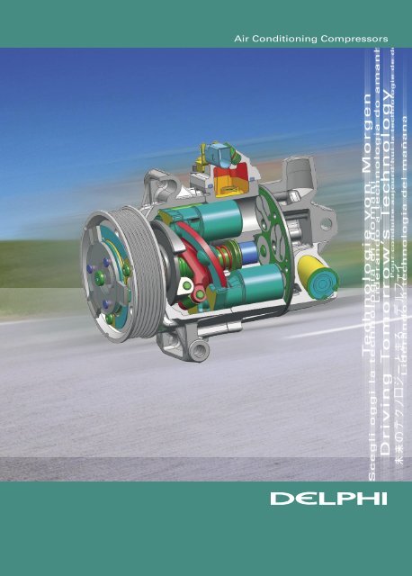
<strong>Air</strong> <strong>Conditioning</strong> <strong>Compressors</strong>
I n t r o d u c t i o n<br />
Th e p a s s e n g e r c o m p a r t m e n t o f a modern<br />
a u t o m o b i l e o ffe r s a ve r y d i ffe r e n t environ-<br />
m e n t t o t h a t o f a ve h i c l e f r o m f i ft y years<br />
a g o . As we l l a s t h e e r g o n o m i c a l l y designed<br />
s e a t i n g a n d i n s t ru m e n t l ayo u t , t h e all round<br />
v i s i b i l i t y a n d t h e e ff i c i e n t u s e o f space,<br />
t o d ay ’s p a s s e n g e r h a s c o n t r o l ove r air tem-<br />
Vi ew o f i n s t ru m e n t p a n e l a n d H VAC c o n t r ols<br />
Th e ve r y h e a r t o f t h e a i r c o n d i tioning sys -<br />
t e m i s t h e c o m p r e s s o r. I ts key t a sks are to<br />
g e n e r a t e t h e r e q u i r e d flow o f r efrigerant<br />
a r o u n d t h e s ys t e m a n d a t t h e same time<br />
t o c o m p r e s s i t s u ff i c i e n tly t o raise its<br />
t e m p e r a ture a b ove t h e a m bient in order<br />
t h a t h e a t c a n b e r e j e c t e d f r o m t h e system.<br />
Th e s e d e m a n d s m u s t b e m e t e fficiently over<br />
ve r y w i d e r a n g e s o f c o mpressor s peed and<br />
a m b i e n t c o n d i t i o n s . A t the same time ver y<br />
d e m a n d i n g n o i s e g e n e r a t ion c o n s t raints and<br />
ex p e c t a t i o n s o f d u r a b i l i t y have to be met.<br />
A i r C o n d i t i o n i n g<br />
C y c l e<br />
I t i s s e l f ev i d e n t t h a t h e a t t e n d s to flow<br />
f r o m high temperatu r e to low. If we wish to<br />
p r ov i d e c o o l i n g a t a l o c a t i o n i n a h i g h tempe-<br />
r a tu r e e nv i r o n m e n t t h e n we a r e e ffectively<br />
a s k i n g h e a t t o f l ow f r o m l ow t e mperature<br />
t o h i g h . To a ch i eve t h i s i t i s n e c essar y to<br />
o p e r a t e a t h e r m o d y n a m i c c yc l e i n which a<br />
perature, qualit y and movement in all corners<br />
of the vehicle. The modern heating , ventila-<br />
ting and air conditioning system (HVAC) can<br />
ensure that thermal comfort and all round<br />
visibilit y are delivered in environments that<br />
range from the heat of Phoenix Arizona to<br />
the coldest Scandinavian winter.<br />
E x p a n d e d v i ew o f a m o d e r n<br />
H VAC c o m p r e s s o r<br />
refrigerant at a low temperature is used to<br />
extract heat from the location to be cooled.<br />
The refrigerant is subsequently compressed<br />
until it becomes hot enough to be able to<br />
reject heat to the ambient. After cooling to<br />
near ambient temperature by the a mbient<br />
air, it is expanded back to low pressure, a<br />
process which generates further refrigerant<br />
temperature reduction that becomes low<br />
enough to be used for cooling at the re-<br />
quired location. The cycle is complete. The
e q u i r e d c o o l i n g i s t h u s a ch i eve d b ut at the<br />
ex p e n s e o f t h e wo r k n e cessar y t o drive the<br />
c o m p r e s s o r.<br />
heat rejected to ambient<br />
expansion device<br />
T h e A u t o m o t i v e<br />
A i r C o n d i t i o n i n g<br />
A p p l i c a t i o n<br />
Th e a u t o m o t i ve a p p l i c ation places ver y<br />
s p e c i a l d e m a n d s o n t h e air c o n ditioning sys-<br />
t e m . A t y p i c a l ve h i c l e s ys t em has a similar<br />
c o o l i n g c a p a c i t y t o t h a t r e q uired for the air<br />
c o n d i t i o n i n g o f a s m a l l h o use d e spite the<br />
va s t d i ffe r e n c e i n vo l u m e s t o b e c ooled. The<br />
r e a s o n s fo r t h i s a r e t wo fold. Firstly cooling<br />
d u t y p e r u n i t vo l u m e i s m u ch higher for the<br />
ve h i c l e b e c a u s e h e a t t ransfe r c o efficients<br />
b e t we e n h o t a m b i e n t a ir a n d t h e outside<br />
s u r fa c e s a r e m u ch h i g h e r d u e t o movement<br />
o f t h e ve h i c l e t h r o u g h t h e a i r. Secondly<br />
t h e p r o p ortion o f t h e e nclosure consisting<br />
o f g l a s s i s ve r y h i g h fo r t h e vehicle – a<br />
fa c t o r t h a t m a ke s t h e e ffe c t o f direct solar<br />
r a d i a t i o n h e a t i n g ve r y h i g h. O n t op of this<br />
a p a r t i c u l a r l y d e m a n d i n g r e q u i r ement is to<br />
c o o l t h e cabin ve r y r a p i d l y a ft e r t he vehicle<br />
h a s b e e n s o a ke d i n a n a m bient t e mperature<br />
o f 4 0 ° C or h i g h e r. A t t h e s t a r t o f the cool<br />
d ow n t e mperatu r e s i n t he c a bin c an be as<br />
h i g h a s 6 0 o r 7 0 ° C .<br />
condenser<br />
evaporator<br />
S ch e m a t i c o f a i r c o n d i t i o n i n g c yc l e<br />
compressor<br />
heat absorbed from cabin<br />
A n o t h e r s i g n i f i c a n t way i n w h ich a utomotive<br />
a i r c o n d i t i o n i n g d i ffe r s from t h e domestic<br />
o r c o m m e r c i a l ve r s i o n is t h e q u estion of<br />
c o m p r e s s o r d r i ve . I n t he ve h icle the com-<br />
p r e s s o r i s b e l t d r i ve n by t h e e n g i ne so that<br />
i n d e p e n d e n t c o n t r o l over t h e c ompressor<br />
s p e e d i s n o t p o s s i b l e . This o bv i ously has<br />
s i g n i f i c a n t i m p l i c a t i o n s fo r sys t e m control<br />
a n d m e a n s t h a t t h e r e c an b e calls for high<br />
s ys t e m perfo r m a n c e a t t imes when the<br />
c o m p r e s s o r s p e e d i s ve r y l ow. A n import ant<br />
implication of this is that the compressor<br />
drive shaft must pass out of the compres-<br />
sor casing with the result ant potential for<br />
refrigerant leakage. Hermetic compressors<br />
are not possible and ver y effective shaft<br />
seals must be used. A second implication<br />
of the external drive is that the compressor<br />
must be engine mounted so that lengths of<br />
flexible hose must be introduced to accom-<br />
modate relative movement bet ween engine<br />
and chassis mounted components.<br />
As with other air conditioning applications<br />
system efficiency is ver y import ant and the<br />
automotive application is no exception. While<br />
the characteristics of all the major compo-<br />
nents in the system contribute to overall ef-<br />
ficiency any compressor inefficiencies must<br />
be kept to a minimum. A further feature of<br />
the compressor that requires serious con-<br />
sideration is its intrinsic noise generation<br />
- modern vehicle noise requirements mean<br />
that the compressor must be ver y quiet and<br />
vibration free.<br />
And finally, three further requirements of<br />
the compressor, specific to the automotive<br />
application, but which apply equally to ever y<br />
vehicle component – are stringent con-<br />
straints on size, weight and cost.<br />
Th e ch a l l e n g e o f c o m p r e s s o r p a ck a g i n g<br />
As a result of all these constraints deriving<br />
from the use of an engine driven compres-<br />
sor, it is often suggested that an electrically<br />
driven system would provide a much better<br />
solution. The reason that it is not feasible<br />
on current vehicles is insufficient electrical<br />
power is available and its application must<br />
await the widespread implement ation of high<br />
powered and efficient integrated st arter/<br />
generators. The applications in which an<br />
electrical compressor would make real sense<br />
however are in hybrid and fuel cell vehicles<br />
where sufficient electrical power is readily<br />
available.
Th e h i g h e ff i c i e n c y o f m o d e r n e n g ines can<br />
l e a d t o t h e s i tu a t i o n i n which i n s u ff icient re-<br />
j e c t e d h e a t i s ava i l a b l e fo r comfo r t heating .<br />
Th i s fa c t h a s p r o m p t e d t h e s u g g estion that<br />
t h e a i r c onditioning s ys tem b e o p erated in<br />
r eve r s e a s a h e a t p u m p t o s u p p l e ment the<br />
e n g i n e h e a t a n d t h e v i a b i lit y o f the concept<br />
h a s b e e n d e m o n s t r a t e d o n a n u m b er of plat-<br />
fo r m s . Th e i m p l i c a t i o n s fo r t h e c o mpressor<br />
a r e t h a t t h e r e q u i r e d o perating life can be<br />
n e a r l y d o u b l e d a n d t h e c ompressor ambient<br />
s a fe o p e r a t i n g t e m p e r a tu r e r a n g e must be<br />
ex t e n d e d d ow nwa r d s t o minus 20°C.<br />
D e l p h i ve h i c l e w i t h H e a t Pu m p s u p p l e m e n t a r y h e a t i n g<br />
R e f r i g e r a n t I s s u e s<br />
Th e a u t o m o t i ve a i r c o n ditioning industr y<br />
r e s p o n d e d p r o - a c t i ve l y t o t h e d emands of<br />
t h e 19 8 7 M o n t r e a l Pr o tocol a n d by 1994,<br />
2 ye a r s e a r l y, t h e ch a n g e ove r f r o m R12 to<br />
R 13 4 a wa s c o m p l e t e fo r a ll ve h icle produc-<br />
t i o n l i n e s i n t h e d eve l oped wo rld. It soon<br />
b e c a m e a p p a r e n t t h a t t h is m ay n ot be the<br />
e n d o f t h e s t o r y a n d w i th i ncreasing pene-<br />
t r a t i o n o f a i r c o n d i t i o n i n g i n t h e European<br />
m a r ke t t ogether w i t h t he d e mands of the<br />
Kyo t o Pr o t o c o l p r e s s u r e has b u ilt to make<br />
ch a n g e s t o s t i l l f u r t h e r r e d uce the potential<br />
c o n t r i b u t i o n o f a i r c o nditioning systems<br />
t o g l o b a l wa r m i n g . A n ew D i r ective has<br />
r e c e n t l y c o m p l e t e d i t s p r o g r ess t h r ough the<br />
E u r o p e a n l e g i s l a t i ve p r o cess. I t r e q uires the<br />
e l i m i n a t i o n o f R 13 4 a f r om a ll n ew models<br />
f r o m 2 011 a n d f r o m a l l n ew ve h icles by 2017.<br />
Th e c u rrently c o n s i d e r ed alternatives are<br />
R 15 2 a w i th a g l o b a l wa rming p o t e ntial less<br />
t h a n 10 % o f t h a t o f R 13 4 a, o r t h e so-called<br />
‘ n a tu r a l ’ r e f r i g e r a n t R 744 ( carbon dioxide).<br />
R 15 2 a h a s t h e r m o d y n amic characteristics<br />
ve r y s i m i l a r t o t h o s e o f R 13 4a a nd will be<br />
d i r e c t l y u s a b l e w i t h current c ompressor<br />
t e ch n o l o g y. I t s p o t e n t i a l d r aw back is a<br />
d e g r e e o f f l a m m a b i l i t y that h as made the<br />
i n d u s t r y reluct a n t t o c onsider i t. More re-<br />
c e n t l y o t h e r l a r g e ch e m i c al c o m panies have<br />
a n n o u n c e d t h e p o t e n t i a l ava ilabilit y of new<br />
a l t e r n a t i ve s . L i tt l e i s k n ow n a b o u t them at<br />
t h i s s t a g e b u t i t i s a s s u m e d t hat they too<br />
wo u l d f u n c t i o n w i t h c u rrent c ompressor<br />
t e ch n o l o g y. Th e r e m u s t b e a q u estion as to<br />
w h e t h e r t h e n e c e s s a r y d eve l o pment and<br />
testing and then implement ation of the<br />
necessar y manufacturing capacit y can be<br />
completed in time to meet the requirements<br />
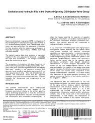
of the European legislation. If R744 becomes<br />
the chosen route the implications for com-<br />
pressor technology are ver y far-reaching . <strong>Air</strong><br />
conditioning systems with R744 need com-<br />
pressors with displacement of only a fifth<br />
of that required for R134a but operating at<br />
much higher pressures. Discharge pressures<br />
of 120 bar are normal compared with a t ypi-<br />
cal 18 bar for an R134a system. As can be<br />
imagined, these factors have big implications<br />
for the compressor layout and structural<br />
strength requirements and also represent a<br />
particularly severe shaft seal challenge.<br />
Pressure - MPa<br />
100<br />
10<br />
1<br />
100<br />
-40°C<br />
0°C<br />
200<br />
40°C<br />
80°C 120°C 160°C 200°C<br />
0°C<br />
40°C<br />
300 400<br />
Enthalpy - kJ/kg<br />
500<br />
I d e a l i ze d p r e s s u r e e n t h a l py d i a g r a m o f C O 2 c yc l e<br />
C o m p r e s s o r<br />
Te c h n o l o g i e s<br />
<strong>Air</strong> conditioning began to become available<br />
for vehicles in the early 1950s. From the<br />
beginning a number of different compressor<br />
technologies have been used. The earliest<br />
systems used piston compressors in various<br />
configurations. The Frigidaire F5, a five pis-<br />
ton wobble plate configuration, used in the<br />
earliest GM vehicles with air conditioning<br />
was first produced in 1956 – it weighed in at<br />
18kg! The R4 compressor with a scotch yoke<br />
mechanism was first produced by Harrison<br />
(now <strong>Delphi</strong>) in 1974 and remained in pro-<br />
duction until 1995. It was 190mm in overall<br />
diameter and weighed 9kg .<br />
A n e a r l y<br />
c o m p r e s s o r,<br />
t h e D e l p h i R 4<br />
80°C<br />
120°C<br />
600<br />
160°C<br />
200°C<br />
700
Th e p r e fe rred c o n f i g u r ation fo r a piston<br />
c o m p r e s s o r s o o n m ove d t o a d o u ble acting<br />
s wa s h - p l a t e d e s i g n o f w h ich t h e Harrison<br />
( D e l p h i ) H D 6 i s t y p i c a l . Th e fixe d swash-<br />
p l a t e i s h e l d b e t we e n t h e o p p osing ends<br />
o f t h e d o u b l e p i s t o n by a pair o f s hoes and<br />
t wo s t e e l balls.<br />
S e c t i o n t h r o u g h a n e a r l y f i xe d s wa s h-plate<br />
c o m p r e s s o r, t h e D e l p h i H D 6<br />
A s e c o n d p o s i t i ve d i s p l a c ement c onfigura-<br />
t i o n u s e d i s t h e s l i d i n g va n e . I t o ffers ad-<br />
va n t a g e s o f c o m p a c t n e ss a n d l ow cost but<br />
c a rries t h e p e n a l t y o f ve r y p o o r e fficiency at<br />
h i g h p r e s s u r e r a t i o s .<br />
Th e o t h e r m a i n c o n f i g u r a tion i s t he scroll<br />
c o m p r e s s o r i n w h i ch o n e s c r oll w i th an in-<br />
vo l u t e s u r fa c e o r b i t s i n side a fixe d second<br />
s c r o l l o f t h e s a m e s h a pe. I t can be seen<br />
f r o m t h e f i g u r e t h a t t h e c o n t a c t points of<br />
t h e scrolls enclose a cav it y of reducing size<br />
( s h a d e d green) that move s from the outside<br />
t o t h e c e n t r e a s t h e o n e scroll o r b i ts inside<br />
t h e o t h e r. Th e r e s u l t i s a n i n d u c tion of gas<br />
a t t h e p e r i p h e r y o f t h e scroll a n d deliver y<br />
o f c o m p r e s s e d g a s a t t h e c e n t r e. These<br />
c o m p r e s s o r s a r e ve r y e ff icient a nd quiet<br />
b u t r e p r esent a s i g n i f icant ch allenge for<br />
m a n u fa c tu r e a n d h e n c e fo r c o s t. They have<br />
t h e d i s a d va n t a g e t h a t a l t h o u g h a variable<br />
ve r s i o n o f t h i s c o m p r e s sor i s p o ssible, the<br />
s u p e r i o r e ff i c i e n c y a d va n t a g e is lost.<br />
I l l u s t r a t i o n o f Scroll compression process<br />
Early compressors were all fixed displace-<br />
ment and system control was achieved by<br />
switching the compressor on and off by<br />
means of an electro-mechanical clutch<br />
cont ained within the compressor pulley.<br />
As consideration began to be given to the<br />
application of air conditioning to smaller<br />
vehicles with smaller engines it was found<br />
that the significant and sudden increase in<br />
engine load that resulted from compressor<br />
switching caused problems for the small<br />
engine with result ant issues of drivabilit y.<br />
A compressor with variable displacement<br />
offered the solution to this problem. In 1985<br />
Harrison (<strong>Delphi</strong>) were the first to go into<br />
series production with a variable compres-<br />
sor, the V5, a wobble plate design with five<br />
pistons.<br />
Th e m e ch a n i s m o f a va r i a b l e wo b b l e p l a t e c o m p r e s s o r<br />
Although scroll, vane and piston compres-<br />
sors are all still in use in automotive applica-<br />
tions, the piston compressor is dominant.<br />
Where the combination of efficiency and<br />
controllabilit y is the key requirement, piston<br />
compressors offer the best solution.<br />
P i s t o n C o m p r e s s o r s<br />
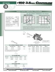
The compressor has the t ask of inducing gas<br />
at a low suction pressure and delivering it at<br />
a higher discharge pressure. It achieves this<br />
by using reed valves that operate automa-<br />
tically to control the fluid flow into and out of<br />
the cylinders. St arting with the piston at top<br />
dead centre the pressure in the small clear-<br />
ance volume will be close to the discharge<br />
pressure as the piston has just delivered its<br />
charge. As the piston recedes and the pres-<br />
sure in the clearance volume falls, the delive-<br />
r y reed valve closes automatically, driven by<br />
the discharge pressure. Since the clearance
vo l u m e i s s m a l l , t h e p r e s s u r e d r o ps quickly<br />
u n t i l i t i s b e l ow t h e s u c tion p r e ssure. At<br />
t h i s s t a g e t h e i n t a ke valve o p e n s and the<br />
f u r t h e r m ove m e n t o f t h e p iston induces<br />
f r e s h ch a r g e .<br />
Cylinder Pressure - bar<br />
25<br />
20<br />
15<br />
10<br />
5<br />
0<br />
suction pressure P s<br />
discharge pressure P d<br />
5 10<br />
15 20<br />
Cylinder volume - cm 3<br />
I n d i c a t o r d i a g r a m fo r s wa s h - p l a t e c ompressor<br />
A ft e r b o ttom d e a d c e n t re t h e p iston com-<br />
p r e s s e s t h e g a s i n d u c e d i n t o t h e cylinder<br />
u n t i l i t r e a ch e s t h e d i s charge p r essure. At<br />
t h i s s t a g e t h e d e l i ve r y valve i s o p e ned auto-<br />
m a t i c a l l y by t h e p r e s s u r e d i ffe r e ntial and<br />
t h e c o m p r e s s e d ch a r g e is delive r ed.<br />
Th e r e a r e s eve r a l key fe a tu r e s o f this ove -<br />
r a l l p r o c e s s i m p o r t a n t for p e r fo rmance and<br />
e ff i c i e n c y. Th e c l e a r a n c e volume must be as<br />
s m a l l a s p o s s i b l e w i t h o u t risking interfe -<br />
r e n c e b e t we e n t h e p i s t on a n d t h e cylinder<br />
h e a d a s a r e s u l t o f d i ffe r e n tial t h e r mal expan-<br />
s i o n o r s t r e s s e ffe c t s . Th e c o nsequences<br />
o f f i n i t e c l e a r a n c e vo l u m e a r e p rincipally<br />
i n d i c a t e d by t h e c o m p r essor volumetric<br />
e ff i c i e n c y w h i ch i s t h e ratio o f t he volume<br />
o f d e l i ve red g a s m e a s u red a t t h e suction<br />
p r e s s u r e relative t o vo l ume displaced by the<br />
p i s t o n . Th e d y n a m i c r e s p o nse characteris-<br />
t i c s o f t h e r e e d va l ve s are a lso i mport ant.<br />
Vo l u m e t r i c e ff i c i e n c y i s a lso impacted by the<br />
q u a n t i t y o f g a s t h a t l e a k s p ast t he pistons<br />
t o t h e c r a n k c a s e , w h i ch is d e t e rmined by<br />
p i s t o n s e a l i n g a n d c l e a r a nces.<br />
E ff i c i e n c y D e f i n i t i o n<br />
volumetric η v<br />
isentropic η s<br />
mechanical η m<br />
Ta b l e o f c o m p r e s s o r e ff i c i e n c i e s<br />
delivered volume<br />
displaced volume<br />
ideal minimum work needed<br />
work done to compress gas<br />
work done on compressed gas<br />
work input to compressor shaft<br />
The second measure of compressor perfor-<br />
mance qualit y is the isentropic efficiency.<br />
It is given by the ratio of the theoretical<br />
minimum work required to compress the gas<br />
from suction to discharge pressure relative<br />
to the work actually done. The theoretical<br />
minimum is based on an idealized ‘isentro-<br />
pic’ process in which no turbulence genera-<br />
tion or viscosit y effects occur. The third<br />
measure of compressor performance qualit y<br />
is the mechanical efficiency. This is the ratio<br />
of the work actually done on the gas relative<br />
to the measured power input to the com-<br />
pressor shaft. The difference bet ween these<br />
t wo figures is due to friction.<br />
V a r i a b l e P i s t o n<br />
C o m p r e s s o r s<br />
As st ated above, Harrison (now <strong>Delphi</strong>) was<br />
the first to go into series production with a<br />
variable compressor. The wobble plate that<br />
drives the pistons with this design is free<br />
to tilt so that the piston stroke, and hence<br />
displacement can be changed. The wobble<br />
plate mechanism allows ver y short and<br />
compact pistons to be used. The ball-ended<br />
connecting rods are swaged into the pistons<br />
and wobble plate which results in strong ,<br />
low friction and ver y simple joints. The fact<br />
that the connecting rods are tilted slightly<br />
during compression as a result of the wobble<br />
plate movement means that the forces act-<br />
ing do not all lie along the piston axes. The<br />
result is that higher vibrational harmonics<br />
can be generated which makes management<br />
of compressor noise more of a challenge<br />
than with later generations of swash-plate<br />
compressor. Nonetheless the value of this<br />
configuration is illustrated by the fact that it<br />
is still produced at a rate of several million<br />
units per year worldwide for inst allation in<br />
new vehicles as original equipment, offering<br />
a good compromise bet ween cost and the<br />
functionalit y of a variable displacement com-<br />
pressor.<br />
The next generation of variable compres-<br />
sors used a swash-plate mechanism, largely<br />
because of its advant ages of low vibration<br />
and noise. The mechanism by which the<br />
compressor displacement is controlled can<br />
be described in principle relatively simply,<br />
but in fact the actual displacement of the<br />
compressor in any given situation results<br />
from a quite complex interaction of forces.
Va r i a b l e s wa sh-plate compressor show i n g m e ch a n i s m<br />
Th e s wa s h - p l a t e h a s a l i n k a g e m echanism<br />
t h a t a l l ow s i t t o r o t a t e t h u s ch a n g i ng its an-<br />
g l e a n d w i t h i t , t h e p i s t o n d i s p l a c e ment. The<br />
l i n k a g e i s d e s i g n e d s o t h a t t h e clearance<br />
vo l u m e r e m a i n s a s c o n s t a n t a n d small as<br />
p o s s i b l e ove r t h e f u l l s wa s h - p l a te angle<br />
r a n g e f r o m f u l l s t r o ke t o m i n i m u m stroke.<br />
Th i s s wa s h - p l a t e s f r e e d o m t o r o t a te means<br />
t h a t u n d e r a ny g i ve n o p e r a t i n g c onditions<br />
i t w i l l t a ke u p a p o s i t i o n t h a t i s determi-<br />
n e d by t h e b a l a n c e o f a l l t h e fo r c es acting<br />
o n i t t h a t t e n d t o c a u s e i t t o r o t a te about<br />
i t s c e n t r e o f r o t a t i o n . Th e f i r s t e l ement of<br />
c o m p l ex i t y i s t h a t t h e c e n t r e o f r o t ation is<br />
n o t f i xe d a s i t s h i ft s l o c a t i o n s l i g htly with<br />
t h e s wa s h - p l a t e a n g l e . I t l i e s fa i r l y near to<br />
t h e s wa s h - p l a t e c o n n e c t i o n w i t h t h e link but<br />
i t s ex a c t l o c u s i s a f u n c t i o n o f t h e linkage<br />
m e ch a n i s m l o c a t i o n , d i m e n s i o n s a nd of the<br />
s wa s h - p l a t e a n g l e . Th e m o s t o bv i o us force<br />
t h a t c o m e s i n t o p l ay i s t h e g a s pressure<br />
a c t i n g o n t h e p i s t o n c r ow n . E s t i mation of<br />
i t s ave r a ge e ffe c t , h oweve r i s c o mplex as<br />
t h e c y l i n d e r p r e s s u r e va r i e s g r e a t l y around<br />
t h e c yc l e . A t t h e s a m e t i m e i t s l i n e of action<br />
i s c o n t i n ually ch a n g i n g a n d h e n c e so is the<br />
e ffe c t i ve t o r q u e i t exe r t s a b o u t t he centre<br />
o f r o t a t i o n . Th i s t o r q u e w i l l o bv i o usly tend<br />
t o u p s t r o ke t h e c o m p r e s s o r.<br />
A l e s s o bv i o u s s o u r c e o f t o r q u e g eneration<br />
o n t h e s wa s h - p l a t e i s t h e i n e r t i a o f the pis-<br />
t o n s w h i ch a r e r e p e a t e d l y a c c e l e r ated and<br />
d e c e l e r a t e d a s t h e c o m p r e s s o r i s operated.<br />
I t m i g h t b e t h o u g h t t h a t t h e e ffe ct of the<br />
fo r c e s fo r a c c e l e r a t i o n a n d d e c eleration<br />
c a n c e l e a ch o t h e r o u t b u t i n fa c t t he piston<br />
Ta b l e o f s wa s h - p l a t e t o r q u e g e n e r a t i n g m e ch a n i s m s<br />
is accelerated upwards over the half of the<br />
swash-plate furthest from its centre of rot a-<br />
tion and correspondingly decelerated over<br />
the half nearest to the centre of rot ation.<br />
The former therefore exerts greater torque<br />
and the net result is a tendency to upstroke<br />
which is proportional to the square of the<br />
piston speed and thus becomes significant<br />
at higher compressor speeds.<br />
A second torque generating force that is a<br />
similar function of compressor speed comes<br />
from centrifugal affects acting on both the<br />
link mechanism and the swash-plate itself. If<br />
one considers the t wo halves of the swash-<br />
plate nearest and most remote from the cen-<br />
tre of rot ation it is clear that the centrifugal<br />
forces of the more remote half generate the<br />
greater torque and the net result will be a<br />
tendency to destroke the compressor.<br />
Further forces generating rot ation torque<br />
can come from the fitting of upstroke and/or<br />
downstroke springs. These can be inst alled<br />
on the shaft to assist the upstroke /down-<br />
stroke process under some compressor opera-<br />
ting conditions and if fitted will obviously<br />
contribute to the overall balance of torques.<br />
Here the effect will be a simple function of<br />
the swash-plate angle.<br />
M e ch a n i s m E ffe c t Comment<br />
The final contributor to the balance of tor-<br />
ques is that generated on the underside<br />
of the pistons by the crank case pressure.<br />
Although the crank case pressure remains<br />
const ant around the cycle its line of action<br />
around the plate must be integrated to ob-<br />
t ain an average net torque. It is the abilit y to<br />
control this pressure that allows the balance<br />
to be shifted and thus the swash-plate angle<br />
to be controlled. Crank case pressure is con-<br />
trolled with bleeds from both suction and<br />
high side. The small suction bleed is usually<br />
permanent and the high side bleed is con-<br />
trolled by means of a valve. If the high side<br />
bleed is closed the suction bleed pumps the<br />
crankcase down to suction pressure with the<br />
result that the compressor operates at full<br />
Cy l i n d e r p r e s s u r e U p s t r oke Integrated around swash-plate<br />
P i s t o n i n e r t i a U p s t r oke Significant at high speed<br />
C e n t r i f u gal fo r c e s D e s t r oke Significant at high speed<br />
S p r i n g s U p s t r oke/destroke Where fitted<br />
C r a n k c a s e p r e s s u r e D e s t r oke Adjusted for control
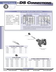
s t r o ke . I f t h e d i s ch a r g e p r e s s u r e gets too<br />
h i g h , t h e h i g h p r e s s u r e b l e e d c a n b e opened<br />
a n d t h e c r a n k c a s e p r e s s u r e i n c r eases. At<br />
s o m e s t a g e i t w i l l b e h i g h e n o u g h for the<br />
b a l a n c e o f t o r q u e s t o d e s t r o ke t h e compres-<br />
s o r. Th e c o n t r o l h a s b e e n a ch i eve d .<br />
Swash-Plate Angle - radians<br />
0,4<br />
0,3<br />
0,2<br />
0,1<br />
0,0<br />
0 2 4 6 8 10 12 14 16<br />
Crank Case Pressure - bar<br />
C o m p r e s s o r control cur ve s<br />
Th e h i g h p r e s s u r e c o n t rol va lve c an be an<br />
a u t o m a t i c , s p r i n g o p e r a t e d va lve o r an elec-<br />
t r i c a l l y s w i t ch e d a n d e l e c t r o nically control-<br />
l e d va l ve . Th e fo r m e r c o nfiguration is known<br />
a s p n e u m a t i c c o n t r o l , t h e latt e r is called<br />
ex t e r n a l c o n t r o l .<br />
Th e d o m i n a n t e l e m e n t o f sys t e m control<br />
i s t h e t h e r m a l ex p a n s i o n valve t h at acts to<br />
m a i n t a i n a give n degree of superheat of the<br />
r e f r i g e r a n t l e av i n g t h e eva p o r a t or. If the<br />
eva p o r a t o r p r e s s u r e b e comes t o o low and<br />
t h e r i s k of eva p o r a t o r f reezing o ccurs, the<br />
p n e u m a t i c c o n t r o l va l ve c o m es i n to opera-<br />
t i o n t o r educe t h e c o mpressor s troke and<br />
m a i n t a i n t h e r e q u i r e d eva p o rator pressure.<br />
Th e a u t o m a t i c c o n t r o l m echanism comes<br />
f r o m t h e b e l l ow s w h i ch i s u n d e r permanent<br />
va c u u m on i t s i n s i d e a nd ex p o s ed to the<br />
s u c t i o n p r e s s u r e o n t he o u t side. If this<br />
p r e s s u r e d i ffe r e n t i a l fa l ls t o o l ow due to<br />
l ow s u c t i o n p r e s s u r e t h e b ellow s expand<br />
t o d r i ve t h e n e e d l e t o open t h e c onnecting<br />
p a s s a g e b e t we e n d i s ch a r g e p r e ssure and<br />
c r a n k c a s e . Th e r e s u l t i n g i n c r ease in crank<br />
c a s e p r e s s u r e l e a d s t o a r e d uction in stroke<br />
w i t h t h e c o n s e q u e n t i a l r e d uction in refri-<br />
g e r a n t m a s s f l ow r a t e a n d i ncrease in suc-<br />
t i o n p r e s s u r e . As t h e eva p o r a t o r pressure<br />
i n c r e a s e s t h e p r e s s u r e diffe r e n tial drives<br />
t h e n e e d l e t o c l o s e t h e c o n n ecting passage<br />
b e t we e n d i s ch a r g e p r e s s u r e a n d c rank case.<br />
Th e c r a n k c a s e p r e s s u r e falls a s a result of<br />
t h e s u c t i o n b l e e d a n d t h e c ompressor stroke<br />
i n c r e a s e s .<br />
9<br />
12 15<br />
Compressor speed: 1000 min -1<br />
Suction pressure: 3 bar<br />
Cur ves marked with head<br />
pressure in bar.<br />
S e c t i o n t h r o u g h<br />
p n e u m a t i c c o m p r e s s o r<br />
c o n t r o l va l ve<br />
The use of external control gives an extra<br />
degree of flexibility. Pneumatic control main-<br />
tains evaporator pressure so that air-off<br />
temperatures remain a few degrees above<br />
0°C and any need for higher temperatures<br />
than this are achieved by mixing with warm<br />
ambient or recirculated air. As a result more<br />
compressor work is done to cool the air<br />
down to the low temperature than is really<br />
necessar y. Ver y significant energy savings<br />
can be made by using the external control<br />
to manage the system capacit y so that only<br />
sufficient cooling is provided to meet the<br />
real need so that significant reheating of<br />
the comfort air is not needed.<br />
T his p ote ntial fo r e n e rg y s av i n g i s t h e m o s t<br />
i m p o r t a nt a s p e c t of ex te r n a l e l e c t ronic c o n -<br />
t ro l b u t i t a l s o of fe r s other a d v a nt a g e s such<br />
a s d e - s t roking a t s y s te m s hut d ow n s o t h a t<br />
t h e e n g i n e l o a d fe l t by t h e e n g i n e a t s y s te m<br />
s t a r t - u p c a n b e g r a d u a lly i n c re a s e d – k n ow n<br />
a s “s of t s t a r t”. A fur t h e r a d v a nt a g e i s t h e a b i l -<br />
i t y to exe rcise a d e g re e of c o ntro l over c a b i n<br />
humidit y a n d avoid exc e s s i ve d r y n e s s t h a t<br />
c a n o c c u r w i t h simple p n e u m a t i c c o ntro l .<br />
Fixed compressors have electromagnetically<br />
operated clutches to allow system control<br />
by switching the compressor drive on and<br />
off as required. Variable compressors have<br />
traditionally ret ained the clutch to be able<br />
to turn the system off when not required or<br />
should system conditions approach unsafe<br />
operating levels for any reason. A more recent<br />
innovation is the introduction of clutchless<br />
compressors. It is made possible by the<br />
implement ation of external compressor con-<br />
trol. Here the compressor can be destroked<br />
to such an extent that it no longer pumps<br />
and can be permanently driven without<br />
dissipation of significant energy. Typical<br />
destroked energy consumption is only 150W<br />
at 30 0 0rev/min. Ver y small stroke can be<br />
relatively easily achieved and the challenge<br />
is to activate upstroke again when required.<br />
The advant ages are principally packaging<br />
and weight although cost savings are also<br />
possible.<br />
S e c t i o n t h r o u g h e l e c t r o n i c a l l y<br />
c o n t r o l l e d c o m p r e s s o r va l ve
A C o m p r e s s o r R a n g e<br />
One frequently hears a need expressed with<br />
phrases such as: ”I want the most efficient<br />
and lightest component possible.” In reality<br />
however, it is not possible to optimise against<br />
two independent parameters at the same time<br />
- the most efficient possible will not necessa-<br />
rily be the lightest and vice-versa (other than<br />
by coincidence). While optimisation against a<br />
single parameter is possible, the significance<br />
of the second can only then be expressed as<br />
a limit or a constraint. “I want the most effi-<br />
cient component possible weighing less than<br />
1kg.”<br />
It is generally recognised that the automo-<br />
tive industr y sources against the single opti-<br />
misation parameter – cost. While there are<br />
ver y many other constraints within which<br />
they have to operate – both applications and<br />
market based constraints – these can only be<br />
expressed as limiting values. The target will<br />
always be to acquire the product that meets<br />
the needs of the application at the lowest<br />
possible cost. Since the needs expressed as<br />
constraints var y greatly, depending upon appli-<br />
cation, a supplier needs to offer an extensive<br />
range of compressors offering a spectrum of<br />
balances between sophistication and cost in<br />
order to stand a chance of meeting the needs<br />
of a significant proportion of the market. This<br />
will extend from simple fixed compressors to<br />
meet the most straightfor ward applications to<br />
electronically controlled variable compressors<br />
where performance, accuracy and efficiency<br />
play a more important role.<br />
As means of illustration the <strong>Delphi</strong> com-<br />
pressor product range for R134a is indicated<br />
below. <strong>Compressors</strong> are shown with the<br />
I n c r e a s i n g<br />
d i s p l a c e m e n t<br />
S P 0 8<br />
F i x e d<br />
S P10<br />
S P13<br />
S P15<br />
S P17<br />
S P21<br />
SP - fixed displacement<br />
## - displacement in cc/10<br />
Wo b b l e Plate<br />
12 3 V 5 i<br />
13 2 V 5 i<br />
14 4 V 5i<br />
15 1 V 5i<br />
15 6V5i<br />
15 6V5e<br />
D e l p h i e n g i n e - d r i ve n R 13 4 a c o m p r e s s o r r a n g e<br />
trend for both increasing sophistication and<br />
cost going from left to right and increasing<br />
displacement going from top to bottom.<br />
The SP range of fixed swash-plate compressors<br />
each with five double acting pistons represents<br />
the lowest cost solution for applications that<br />
can tolerate the implications of a cycling clutch.<br />
The double piston configuration means that<br />
in effect there are a total of ten compression<br />
cavities which yields very low levels of pres-<br />
sure fluctuation. This feature combined with the<br />
smoothness of the swash-plate drive results in<br />
an inherently quiet compressor.<br />
The V5 range of wobble plate variable compres-<br />
sors has already been described as the original<br />
<strong>Delphi</strong> variable compressor. It has seen con-<br />
siderable refinement over the years and whilst<br />
it cannot compete with the CVC swash-plate<br />
range for quietness and efficiency it represents<br />
a very cost-effective introduction to variable<br />
compressor technology. The dual PTFE piston<br />
rings contribute to low blow-by and good oil<br />
retention.<br />
The Compact Variable Compressor (CVC) range<br />
of compressors uses swash-plate technology<br />
to ensure that a/c system generated noise and<br />
vibration is kept to a minimum. Internally and<br />
externally controlled versions are available.<br />
The externally controlled range of CVC compres-<br />
sors are offered with and without clutch. In the<br />
clutchless compressor the ability to upstroke<br />
again after destroke to a minimum that is only 1<br />
or 2% of maximum stroke is ensured by the very<br />
tight tolerances of the piston and cylinder bore<br />
dimensions. They ensure very low blow-by which<br />
helps maintain low parasitic losses and ensure<br />
that upstroke can be achieved when required.<br />
Variable<br />
Swash-Plate<br />
I n c r e a sing sophistication and cost trend<br />
### - displacement in cc<br />
V - wobble plate<br />
179V7e<br />
# - number of cylinders<br />
i - internal control<br />
e - external control<br />
5CVC120i<br />
6CVC125i<br />
6CVC135i<br />
6CVC140i<br />
6CVC160i<br />
7CVC165i<br />
7CVC185i<br />
# - number of pistons<br />
5CVC120c<br />
CVC - variable swash-plate<br />
6CVC125c<br />
6CVC135c<br />
### - max displacement in cc<br />
6CVC140c<br />
6CVC160c<br />
7CVC165c<br />
7CVC185c<br />
5CVC120e<br />
6CVC125e<br />
6CVC135e<br />
6CVC140e<br />
i - internal control<br />
c - clutchless<br />
6CVC160e<br />
7CVC165e<br />
e - external control<br />
7CVC185e
I t c a n b e s e e n t h a t t h e C VC range is ver y<br />
c o m p r e h e n s i ve . N o t s how n h e r e is the<br />
f u r t h e r f l ex i b i l i t y o ffe r ed by a ver y wide<br />
r a n g e o f p o s s i b l e p i p ing c o n f igurations<br />
w h i ch t o g e t h e r c a rr y t h e implication that a<br />
l a r g e n u m b e r o f d i ffe r e nt c ompressor con-<br />
f i g u r a t i o n s m u s t p a s s d ow n t h e p roduction<br />
l i n e s . I t h a s b e e n c o n c l u d e d by s ome that<br />
t h i s c o m plex i t y i s l i ke l y t o have a negative<br />
e ffe c t o n p r o d u c t q u a l i t y w h e n i n fact the<br />
o p p o s i t e is t ru e . To m a n a g e t h e c omplexit y<br />
a s ys t e m k n ow n a s R F I D – radio f requency<br />
i d e n t i f i c a t i o n – i s u s e d i n w hich each individ-<br />
u a l c o m p ressor c a rries a ch i p w i t h it down<br />
t h e p r o d u c t i o n l i n e . D u ring t h e passage<br />
d ow n the line the ch i p reads and verifies all<br />
t h e i n fo r m a t i o n a b o u t t he i n dividual compo-<br />
n e n t s a s t h ey a r e a s s e m b l e d (manufacturing<br />
d a t e s , d i m e n s i o n s , e t c ) a n d c ommunicates<br />
i t b a ck t o a c e n t r a l c o m puter fo r filing . This<br />
d a t a o n e a ch i n d i v i d u a l c ompressor is then<br />
ava i l a b l e fo r l a t e r a c c e s s s h o uld there be<br />
p r o b l e m s f u r t h e r d ow n t h e l i n e o r problems<br />
f r o m t h e f i e l d . Th e ava i l a b ilit y o f a ll this com-<br />
p r e h e n s i ve a n d d e t a i l e d d a t a c o n t ributes to<br />
t h e e s t a b l i s h m e n t a n d maintenance of the<br />
ve r y h i g h l eve l s o f r e l i a b ilit y r e q u i red by the<br />
a p p l i c a t i o n .<br />
N e w Te c h n o l o g i e s<br />
I n r e c e n t ye a r s a s e r i ous i n t e r est in the<br />
u s e o f R 74 4 a s r e f r i g e rant i n a u tomotive<br />
a i r c o n d i tioning s ys t e m s has b een gene-<br />
r a t e d . E uropean l e g i s l a tion h as recently<br />
b e e n p a s s e d t h a t w i l l fo r c e t h e industr y<br />
t o m ove away f r o m R 13 4a a n d R744 has<br />
b e c o m e t h e l e a d i n g c o n t e n d e r. As a result<br />
D e l p h i i s d eve l o p i n g a r a n g e o f s wash-plate<br />
c o m p r e s s o r s t o m e e t t his n e e d. Current<br />
p r o t o t y p e s h ave f i ve p i s tons a n d maximum<br />
d i s p l a c e m e n t o f 3 0 c c a l though t h e number<br />
o f p i s t o n s i n t h e f i n a l p roduct r a nge is still<br />
u n d e r d eve l o p m e n t . Bo t h f ixe d a n d variable<br />
ve r s i o n s o f d i s p l a c e m e nts o f 15 , 21 and<br />
3 0 c c a r e p l a n n e d . I t i s e nvisaged that for<br />
l ow d i s p l a c e m e n t t h e n umber o f pistons<br />
w i l l b e b e t we e n 5 a n d 7, a t t h e high end it<br />
C o n c l u s i o n<br />
will be bet ween 7 and 9. The reason for this<br />
uncert aint y is that the appropriate balance<br />
bet ween cost and noise/durabilit y has not<br />
yet been est ablished.<br />
D e l p h i C O 2 c o m p r e s s o r<br />
It can be seen that as a result of the ver y<br />
different fluid properties, the displacements<br />
offered are ver y much lower than for R134a.<br />
The range features shaft sealing by face seal<br />
and internal oil separator. The need for the<br />
latter comes from the significant evaporator<br />
performance degradation that occurs with<br />
CO 2 if excess oil is allowed to circulate.<br />
The second new technology concerns com-<br />
pressors for future powertrains, whether<br />
hybrid or fuel cell – the electrically driven<br />
compressor. Under development is a family<br />
of scroll compressors driven by 315 volt<br />
brushless electric motors. Scroll displace-<br />
ments are 28 and 38cc for cooling capacities<br />
of 5.6 and 7.1 kW respectively. The motors<br />
are cooled using the low temperature re-<br />
frigerant vapour from the evaporator with<br />
a result ant motor efficiency of 94%. The<br />
inverter is cooled by conduction from the<br />
same refrigerant and it too has efficiency in<br />
the 94 to 98% range.<br />
1<br />
S e c t i o n t h r o u g h D e l p h i E l e c t r i c C o m p r e s s o r<br />
1 S c r o l l C o m p r e s s o r<br />
2 Pe r m a n e n t M a g n e t M o t o r<br />
3 I nve r t e r a n d I n t e g r a t e d E l e c t r o n i c s<br />
This paper has aimed to present the technical requirements of the compressor for use in<br />
automotive air conditioning applications and to show how the diverse requirements of the<br />
application mean that a supplier must have available a range of technologies and specifi-<br />
cations to be able to meet these needs. It goes on to show how the <strong>Delphi</strong> compressor<br />
product range is designed to give comprehensive coverage and finishes with consideration<br />
of compressors for developmental technologies that are likely to become significant in the<br />
relatively near future.<br />
2<br />
3
<strong>Delphi</strong> Thermal Systems European Headquarters<br />
Avenue de Luxembourg<br />
L - 4940 Bascharage<br />
Grand-Duché de Luxembourg<br />
Tél : +352 50 18 1<br />
Fax : +352 50 18 48 00<br />
w w w . d e l p h i . c o m<br />
©20 06 <strong>Delphi</strong> All rights reserved Today’s Ink s.à r.l 236243-1<br />
About <strong>Delphi</strong> Multi-national: <strong>Delphi</strong> conducts its business operations through various subsidiaries and has headquarter in Troy Michigan USA, Paris, Tok yo and São Paulo, Brazil.