Model-based fault-detection and diagnosis ... - web page for staff
Model-based fault-detection and diagnosis ... - web page for staff
Model-based fault-detection and diagnosis ... - web page for staff

You also want an ePaper? Increase the reach of your titles
YUMPU automatically turns print PDFs into web optimized ePapers that Google loves.
78<br />
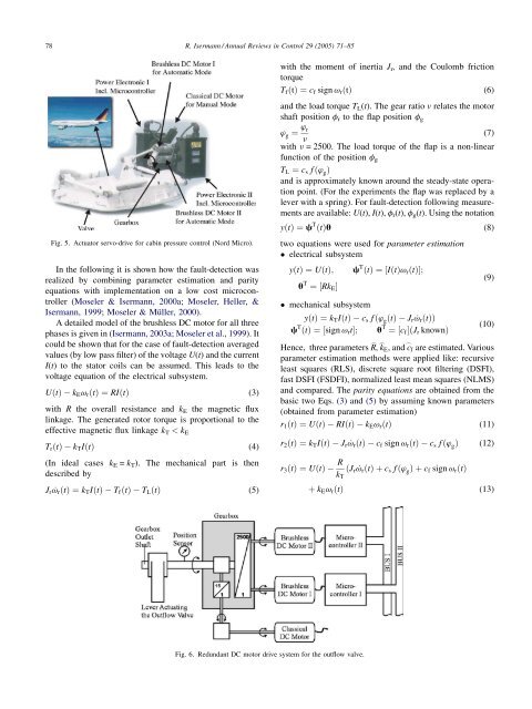
Fig. 5. Actuator servo-drive <strong>for</strong> cabin pressure control (Nord Micro).<br />
In the following it is shown how the <strong>fault</strong>-<strong>detection</strong> was<br />
realized by combining parameter estimation <strong>and</strong> parity<br />
equations with implementation on a low cost microcontroller<br />
(Moseler & Isermann, 2000a; Moseler, Heller, &<br />
Isermann, 1999; Moseler & Müller, 2000).<br />
A detailed model of the brushless DC motor <strong>for</strong> all three<br />
phases is given in (Isermann, 2003a; Moseler et al., 1999). It<br />
could be shown that <strong>for</strong> the case of <strong>fault</strong>-<strong>detection</strong> averaged<br />
values (by low pass filter) of the voltage U(t) <strong>and</strong> the current<br />
I(t) to the stator coils can be assumed. This leads to the<br />
voltage equation of the electrical subsystem.<br />
UðtÞ kEvrðtÞ ¼RIðtÞ (3)<br />
with R the overall resistance <strong>and</strong> k E the magnetic flux<br />
linkage. The generated rotor torque is proportional to the<br />
effective magnetic flux linkage k T < k E<br />
TrðtÞ kTIðtÞ (4)<br />
(In ideal cases kE = kT). The mechanical part is then<br />
described by<br />
Jr ˙vrðtÞ ¼kTIðtÞ TfðtÞ TLðtÞ (5)<br />
R. Isermann / Annual Reviews in Control 29 (2005) 71–85<br />
with the moment of inertia J r, <strong>and</strong> the Coulomb friction<br />
torque<br />
TfðtÞ ¼cf sign vrðtÞ (6)<br />
<strong>and</strong> the load torque TL(t). The gear ratio v relates the motor<br />
shaft position fr to the flap position fg<br />
’ g ¼ ’ r<br />
(7)<br />
n<br />
with n = 2500. The load torque of the flap is a non-linear<br />
function of the position fg<br />
TL ¼ cs f ð’ gÞ<br />
<strong>and</strong> is approximately known around the steady-state operation<br />
point. (For the experiments the flap was replaced by a<br />
lever with a spring). For <strong>fault</strong>-<strong>detection</strong> following measurements<br />
are available: U(t), I(t), fr(t), fg(t). Using the notation<br />
yðtÞ ¼c T ðtÞu (8)<br />
two equations were used <strong>for</strong> parameter estimation<br />
electrical subsystem<br />
yðtÞ ¼UðtÞ; c T ðtÞ ¼½IðtÞvrðtÞŠ;<br />
u T ¼½RkEŠ<br />
mechanical subsystem<br />
yðtÞ ¼kTIðtÞ cs f ð’ gðtÞ Jr ˙vrðtÞÞ<br />
c T ðtÞ ¼½sign vrtŠ; u T ¼½cfŠðJr knownÞ<br />
(9)<br />
(10)<br />
Hence, three parameters R _ , k _<br />
E, <strong>and</strong> c _<br />
f are estimated. Various<br />
parameter estimation methods were applied like: recursive<br />
least squares (RLS), discrete square root filtering (DSFI),<br />
fast DSFI (FSDFI), normalized least mean squares (NLMS)<br />
<strong>and</strong> compared. The parity equations are obtained from the<br />
basic two Eqs. (3) <strong>and</strong> (5) by assuming known parameters<br />
(obtained from parameter estimation)<br />
r1ðtÞ ¼UðtÞ RIðtÞ kEvrðtÞ (11)<br />
r2ðtÞ ¼kTIðtÞ Jr ˙vrðtÞ cf sign vrðtÞ cs f ð’ gÞ (12)<br />
r3ðtÞ ¼UðtÞ<br />
Fig. 6. Redundant DC motor drive system <strong>for</strong> the outflow valve.<br />
R<br />
ðJr ˙vrðtÞþcs f ð’ gÞþcf sign vrðtÞ<br />
kT<br />
þ kEvrðtÞ (13)