Aircraft Carrier Multipath Modeling for Sea-Based JPALS - AWE ...
Aircraft Carrier Multipath Modeling for Sea-Based JPALS - AWE ...
Aircraft Carrier Multipath Modeling for Sea-Based JPALS - AWE ...

You also want an ePaper? Increase the reach of your titles
YUMPU automatically turns print PDFs into web optimized ePapers that Google loves.
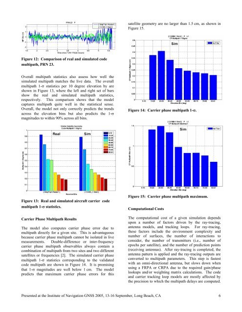
Figure 12: Comparison of real and simulated code<br />
multipath, PRN 23.<br />
Overall multipath statistics also assess how well the<br />
simulated multipath matches the live data. The overall<br />
multipath 1-σ statistics per 10 degree elevation by are<br />
shown in Figure 13, where the left and right set of bars<br />
show the real and simulated multipath statistics,<br />
respectively. This comparison shows that the model<br />
captures multipath quite well in the statistical sense.<br />
Overall, the model not only correctly predicts the trends<br />
across the elevation bins but also predicts the 1-σ<br />
magnitudes to within 90% across all bins.<br />
Figure 13: Real and simulated aircraft carrier code<br />
multipath 1-σ statistics.<br />
<strong>Carrier</strong> Phase <strong>Multipath</strong> Results<br />
The model also computes carrier phase error due to<br />
multipath directly <strong>for</strong> a given site. This is advantageous<br />
because carrier phase multipath cannot be isolated in live<br />
measurements. Double-difference or inter-frequency<br />
carrier phase multipath observables always contain a<br />
combination of multipath from two sites and two different<br />
satellites or frequencies [2]. The simulated carrier phase<br />
multipath 1-σ statistics corresponding to the validated<br />
code multipath are shown in Figure 14. It is promising<br />
that 1-σ magnitudes are well below 1 cm. The model<br />
predicts that maximum carrier phase errors <strong>for</strong> this<br />
satellite geometry are no larger than 1.5 cm, as shown in<br />
Figure 15.<br />
Figure 14: <strong>Carrier</strong> phase multipath 1-σ.<br />
Figure 15: <strong>Carrier</strong> phase multipath maximum.<br />
Computational Costs<br />
The computational cost of a given simulation depends<br />
upon a number of factors driven by the ray-tracing,<br />
antenna models, and tracking loops. For ray-tracing,<br />
these factors include the environment complexity and<br />
number of surfaces, the number of interactions to<br />
consider, the number of transmitters (i.e., number of<br />
epochs per satellite), and the number of prediction points<br />
(receiving antennas). After ray-tracing is completed, the<br />
antenna pattern is applied and the ray-tracing outputs are<br />
converted to multipath parameters. This step is fastest<br />
with an omni-directional antenna, but slows down when<br />
using a FRPA or CRPA due to the required gain/phase<br />
lookups and/or weighting matrix calculations. The code<br />
and carrier tracking loop models are mostly affected by<br />
the precision to which the multipath delays are computed.<br />
Presented at the Institute of Navigation GNSS 2005, 13-16 September, Long Beach, CA 6