WinProp - AWE-Communications
WinProp - AWE-Communications
WinProp - AWE-Communications

You also want an ePaper? Increase the reach of your titles
YUMPU automatically turns print PDFs into web optimized ePapers that Google loves.
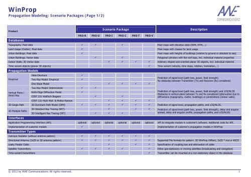
<strong>WinProp</strong><br />
Propagation Modeling: Scenario Packages (Page 1/2)<br />
Product<br />
Databases<br />
Scenario Package Description<br />
PRO-R PRO-U PRO-I PRO-C PRO-T PRO-V<br />
Topography: Pixel data � � � Pixel maps with elevation data (DEM, DTM,...)<br />
Land Usage (Clutter): Pixel data � Pixel maps with classes for land usage<br />
Urban Buildings: Pixel data � Pixel maps with heights of buildings (relative to ground or absolute to sea)<br />
Urban Buildings: Vector data � � Polygonal cylinders with flat roof tops, incl. individual material properties<br />
Indoor Walls: 3D Vector data � � � � Arbitrary shaped and oriented planar 3D objects, incl. individual material<br />
Time variant objects (planar 3D objects) � Time variant (velocity, time steps, rotation, translation,…)<br />
Propagation Models<br />
Empirical<br />
Vertical Plane /<br />
Direct Ray<br />
Hata-Okumura �<br />
Two Ray Model: Empirical �<br />
One Slope Model � � � �<br />
Two Ray Model: Deterministic � �<br />
Knife-Edge Diffraction Model �<br />
COST 231 Walfisch-Ikegami � �<br />
COST 231 Multi Wall & Motley-Keenan � � � �<br />
Prediction of signal level (path loss, power, field strength)<br />
No obstacles between Transmitter (Tx) and Receiver (Rx) considered.<br />
Prediction of signal level (path loss, power, field strength) and LOS/NLOS<br />
Obstacles in vertical plane between Tx and Rx considered (attenuation due to<br />
diffractions (topography, clutter, buildings) or penetrations (indoor walls).<br />
3D Single Path 3D Dominant Path Model (DPM) � � � � � � Prediction of signal level, propagation paths, and LOS/NLOS.<br />
3D Multiple Paths<br />
Interfaces<br />
3D Standard Ray Tracing (SRT) � � �<br />
3D Intelligent Ray Tracing (IRT) � � �<br />
Prediction of signal level (path loss, power, field strength), delay and angular<br />
spread, delay and angular profile, propagation paths, and LOS/NLOS.<br />
Application Programming Interface (API) optional optional optional optional optional optional API to integrate module in customer’s software. Additional costs for API.<br />
Implementation of customer models � Implementation of customer’s propagation models in <strong>WinProp</strong><br />
Transmitter Types<br />
Isotropic Radiator (without antenna pattern) � � � � � �<br />
Directional Antenna (2x2D or 3D antenna pattern) � � � � � � Supported File formats for pattern: 3D <strong>WinProp</strong> (AMan), 2x2D *.msi or ASCII<br />
Leaky Feeder Cable � � � Specification of coupling loss and attenuation of cable<br />
Satellite Transmitters � � � � � Either geo-stationary or moving satellites (broadcasting and navigation)<br />
Time-variant transmitters � Transmitter can be mounted at a non-stationary object in the database<br />
© 2012 by <strong>AWE</strong> <strong>Communications</strong>. All rights reserved. 1
<strong>WinProp</strong><br />
Propagation Modeling: Scenario Packages (Page 2/2)<br />
Product<br />
Prediction Mode<br />
Horizontal<br />
prediction<br />
plane(s)<br />
Scenario Package Description<br />
PRO-R PRO-U PRO-I PRO-C PRO-T PRO-V<br />
Relative prediction height(s) � � � � � � Relative to ground<br />
Absolute prediction height � Absolute height to sea level<br />
Multiple prediction heights (inside buildings) � � � Only in Empirical/Direct Ray/DPM/SRT mode. Not supported in IRT mode.<br />
Arbitrary Arbitrarily oriented prediction planes � Planes oriented arbitrarily in the scenario<br />
prediction Multiple prediction points � � � � � List with multiple prediction points (individual and arbitrary heights)<br />
Time variant predictions (time-variant prediction pixels) � Will be available in V13 (mid 2013)<br />
Database Converters<br />
Pixel: Database converters (Topo & Clutter): (CONV-T & -L) � � Topo & Clutter: ASCII Grid, MSI Planet // Topo: USGS……<br />
Pixel � Vector: Pixel � Vector Data Converters (CONV-P) � � � Conversion of Bitmaps (*.bmp), JPEG (*.lpg), TIFF (*.tif) to vector data<br />
Vector: Urban Vector Buildings: Basic Set (CONV-U) � � MapInfo (ASCII), Arcview Shapefile<br />
Vector: Indoor Vector Objects: CAD Set (CONV-I) � � � AutoCAD *.dwg, *.dxf<br />
Vector: Indoor Vector Objects: Car Set � Nastran, STL (Binary, ASCII), Wavefront<br />
Export of network/transmitter data and simulation results<br />
Export of transmitter data and settings � � � � � � Supported file formats: ASCII Lines<br />
Export of simulation results � � � � � � Supported file formats: ASCII Grid / DXF / Geo Bitmap (*.bmp. *.jpg, *.tiff)<br />
Software Tools<br />
ProMan: Propagation and Network Planning Tool � � � � � � GUI to edit project parameters, visualize prediction results,….<br />
AMan: Antenna Editor (without MASC) � � � � � � GUI to edit, convert, and visualize antenna patterns<br />
WallMan: 3D CAD and GIS Editor (WALL-B) � � � � � GUI to work with 3D CAD and GIS data (Basic module)<br />
WallMan: 3D CAD editor for planar objects (WALL-I) � � � � GUI to work with 3D CAD data with planar objects<br />
WallMan: 3D CAD editor for polygonal cylinders (WALL-U) � � � GUI to work with 3D GIS data with polygonal cylinders<br />
WallMan: 3D CAD editor for time-variant objects (WALL-V) � GUI to work with 3D CAD data with time-variant properties<br />
TuMan: 3D CAD editor for tunnels (WALL-T) � GUI to work with tunnel data (cross sections and trajectories)<br />
Requirements<br />
Packages required to use selected scenario - - - PRO U/I PRO-I PRO-I<br />
Price<br />
Category (Credits) ●●● ●●● ●● ●● ● ●●<br />
© 2012 by <strong>AWE</strong> <strong>Communications</strong>. All rights reserved. 2
<strong>WinProp</strong><br />
Network Planning: Air Interface Packages (Page 1/2)<br />
Air Interfaces<br />
Product<br />
Network Planning Package (Air Interface) Description<br />
NET-B NET-D NET-L NET-O NET-T NET-C NET-G NET-E<br />
Broadcasting (Analogue, FM, etc.). � �<br />
OFDM Broadcasting (DVB-H, DVB-SH, DVB-T, …) � NET-D can be adapted to other OFDM broadcasting interfaces (DAB)<br />
GSM / GPRS / EDGE (arbitrary TDMA air interfaces) � � Can be adapted by the user to any other TDMA air interface<br />
UMTS-FDD (WCDMA) incl. HSPA � � A dynamic system simulator is additionally available (NET-W)<br />
UMTS-TDD / TD-SCDMA � �<br />
CDMA-2000 incl. EV-DO � �<br />
W-LAN IEEE 802.11 a/b/g/n (WiFi) � � �<br />
W-LAN IEEE 802.11 b (WiFi) � �<br />
WiMAX 802.16-2004 (Fixed) & 802.16e (Mobile) � � IEEE 802.16-2004 (Fixed WiMAX) and IEEE 802.16 e (Mobile WiMAX)<br />
LTE � �<br />
TETRA � �<br />
GPS / Galileo �<br />
Extensions<br />
MIMO Technology � �<br />
Distributed Antenna Systems � � � � � Multiple antennas radiating the same signal => superposition, etc.<br />
Satellite transmitters � � � Only if satellite transmitters are supported in propagation scenario<br />
Leaky feeder cables � � � � � � Only if leaky feeder cables are supported in propagation scenario<br />
Number of transmissions modes 0 No limit No limit No limit No limit No limit 0 No limit Multiple transmission modes with individual parameters<br />
Simulator<br />
Static Network Planning � � � � � � � � Interference due to cell load independent from traffic in cells<br />
Dynamic Network Simulation Only available for WCDMA incl. HSPA (ask for details)<br />
Consideration of Interference<br />
Downlink: Cell Load (Relative Tx power) � � � � Relative percentage of max. available power used for interference<br />
Uplink: Noise Rise � � � � Can be specified for each cell individually<br />
Definition of location specific interference � � � � Cell load and noise rise defined location depending via clutter classes<br />
Consideration of polarization for interference � � � � Different linear polarizations of signals influence interference<br />
Interference due to multi path propagation � Only possible in combination with ray-optical propagation model<br />
Adjacent Channel Interference (�) (�) (�) (�) Will be available in Q4-2011<br />
© 2012 by <strong>AWE</strong> <strong>Communications</strong>. All rights reserved. 3
<strong>WinProp</strong><br />
Network Planning: Air Interface Packages (Page 2/2)<br />
Simulation Modes<br />
Product<br />
Network Planning Package (Air Interface) Description<br />
NET-B NET-D NET-L NET-O NET-T NET-C NET-G NET-E<br />
Simulation of horizontal grids on multiple heights � � � � � � � � One height (all scenarios) or multiple heights (only indoor scenarios)<br />
CNP simulation (outdoor & multiple indoor heights) � � � � � � � � CNP urban/indoor simulations (requires PRO-C)<br />
Point to Multi-Point Mode � � � � Simulations for individual points<br />
Time-variant scenarios Network Planning not yet available for time-variant scenarios<br />
Predicted Results<br />
Cell Assignment<br />
and<br />
Consideration<br />
of downlink<br />
transmission<br />
Downlink &<br />
Uplink transmission<br />
modes<br />
Best server / Cell layout � � � � � � � Results are depending on selected algorithm for cell assignment<br />
Neighbor cell list � � � � Neighbor cell list (based on cell assignment)<br />
Max. received power � � � � � � � Max. received power in downlink (e.g. used for cell assignment)<br />
Number received carriers / sites � � � � � � � Number of received carriers / sites /cells in cell assignment<br />
Superposition of carriers � � Superposition of identical carriers (power sum (uncorrelated))<br />
SNIR � � SNIR for each carrier and for best server at each pixel<br />
Soft / Softer handover regions � Type of handover (hard, soft, softer) incl. size of active set<br />
Exposure & Superposition � EMC exposure, superposition of all carriers in freq. band,…<br />
Min. required Tx power � � � � Min. required MS and BS Tx power required for transmission mode<br />
Max. received Rx power � � � � Max. received MS and BS Rx power required for transmission mode<br />
SNIR (Downlink) � � � � Max. available SNIR for transmission mode (in downlink)<br />
Reception probability (DL) � � � � Percentage for coverage incl. fast fading (Rayleigh fading).<br />
For all trans- Nr. of MIMO streams (DL, UL) � � � � Number of received MIMO streams (in MIMO networks)<br />
mission modes Throughput / Bit Rates (DL,UL) � � � � Highest achievable bit rates available for pixel (downlink, uplink)<br />
Definition of Mobile Stations (MS) / User Equipment (UE) / Subscriber Stations<br />
Antenna Pattern Individual antenna pattern for each MS (only in point-to-multipoint)<br />
MS properties for each transmission mode same same individ. individ. individ. individ. same - Same or individual MS properties for each transmission mode<br />
Definition of Base Stations (BS) / Access Points / Satellites / Cells<br />
Number of carriers to be assigned to a cell No limit No limit No limit No limit No limit 1 1 No limit Nr of carriers influences nr of radio links. No carrier assignment.<br />
Noise figure / Cable losses / etc. � � � � � � Default for all BS in network or individual for each BS<br />
Price<br />
Category (Credits) ◊ ◊◊ ◊◊ ◊◊◊ ◊◊ ◊◊◊ ◊ ◊<br />
© 2012 by <strong>AWE</strong> <strong>Communications</strong>. All rights reserved. 4
<strong>WinProp</strong><br />
Add-Ons<br />
Product Description Required Modules Category (Credits)<br />
ConMan<br />
MobileMan<br />
MIMOMan<br />
MASC<br />
StreetMan<br />
Connectivity Simulator for MESH and sensor networks<br />
Based on propagation predictions (with one of the PRO modules). Computes the connectivity between the nodes and displays signal<br />
levels and delays.<br />
Evaluation of prediction results including the antenna pattern at the mobile station<br />
Based on propagation predictions (with one of the PRO modules). The user can specify the antenna pattern of the mobile station (incl.<br />
elevation and azimuth) and a trajectory for the movement of the mobile station. The antenna pattern will be rotated in azimuth<br />
according to the trajectory.<br />
MobileMan computes the signal level along the trajectory and applies the antenna pattern to all rays (multiple propagation paths)<br />
received at the selected locations.<br />
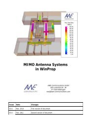
Signal evaluation for MIMO systems<br />
Based on propagation predictions (with one of the PRO modules). The user can specify the MIMO antennas at the base station and at<br />
the mobile station (incl. azimuth and elevation). Different n x m MIMO antennas (linear antenna arrays, separation of antennas,<br />
orientation of antennas, etc.) can be defined.<br />
A trajectory for the mobile station can be defined to simulate the movement in a scenario.<br />
MIMOMan computes the signal level along the trajectory and applies the antenna pattern to all rays (multiple propagation paths)<br />
received at the selected locations.<br />
Multiple Antenna Scenario Configuration<br />
Computation of the combined antenna pattern for multiple antennas mounted at a tower or in front of a wall. Phase shifters for each<br />
antennas as well as power splitters can be defined. The material properties of tower, wall, and mounting elements can be defined.<br />
Computation includes reflected rays (at tower and wall) and the transmission losses due to mounting elements and radoms.<br />
Definition of roads and streets<br />
GUI to define streets and roads with multiple lanes and guardrails. Convenient definition of curves, etc. Export in vector data format to<br />
import the scenarios into WallMan (for further processing).<br />
Arbitrary PRO module ◊◊<br />
Arbitrary PRO module ●<br />
Arbitrary PRO module ●●<br />
AMan ●<br />
WallMan ●<br />
© 2012 by <strong>AWE</strong> <strong>Communications</strong>. All rights reserved. 5