Installing the Dialogic® Brooktrout® TR1034 BRI PCI Fax Board ...
Installing the Dialogic® Brooktrout® TR1034 BRI PCI Fax Board ...
Installing the Dialogic® Brooktrout® TR1034 BRI PCI Fax Board ...

Create successful ePaper yourself
Turn your PDF publications into a flip-book with our unique Google optimized e-Paper software.
<strong>Installing</strong> <strong>the</strong> <strong>Dialogic®</strong><br />
<strong>Brooktrout®</strong> <strong>TR1034</strong> <strong>BRI</strong><br />
<strong>PCI</strong> <strong>Fax</strong> <strong>Board</strong><br />
Part Number: 931-106-05<br />
The <strong>Dialogic®</strong> <strong>Brooktrout®</strong> <strong>TR1034</strong> <strong>BRI</strong><br />
(Basic Rate Interface ISDN) <strong>PCI</strong> boards<br />
(“<strong>TR1034</strong>” or “<strong>TR1034</strong> fax board(s)”)are half-sized,<br />
single-slot <strong>PCI</strong>-bus compatible fax boards. They<br />
provide <strong>the</strong> following:<br />
� On-board <strong>BRI</strong> connections<br />
� V.34 (33.6 Kbps) fax transmission speeds<br />
� Up to four fax and voice channels per board<br />
The <strong>TR1034</strong> <strong>BRI</strong> <strong>PCI</strong> Series boards can be used in<br />
ei<strong>the</strong>r 3.3V or 5V bus (signaling) slots.<br />
You need a fax or voice application to use a<br />
<strong>TR1034</strong> <strong>BRI</strong> <strong>Fax</strong> <strong>Board</strong>. Dialogic does not provide<br />
<strong>the</strong> application or a driver for this board. A driver<br />
comes with <strong>the</strong> application that you purchase.<br />
This installation guide provides information about:<br />
� System Requirements (including telephone<br />
service)<br />
� Setting <strong>the</strong> Module Number<br />
� Setting Termination Jumpers for <strong>the</strong> <strong>BRI</strong> Line<br />
� <strong>Installing</strong> <strong>the</strong> <strong>Fax</strong> <strong>Board</strong><br />
� Recognizing <strong>PCI</strong> Slots<br />
� Connecting <strong>the</strong> Phone Service<br />
� Understanding LED Signals<br />
� Using <strong>the</strong> <strong>Dialogic®</strong> <strong>Brooktrout®</strong> <strong>TR1034</strong> <strong>BRI</strong><br />
<strong>Fax</strong> <strong>Board</strong><br />
� Getting Help<br />
System Requirements<br />
This board must be installed in an enclosure that<br />
meets <strong>the</strong> following specifications:<br />
� A Pentium or later host processor<br />
� A <strong>PCI</strong> bus slot that runs at least 33 MHz and is<br />
32 or 64 bits wide. See Recognizing <strong>PCI</strong> Slots for<br />
more information.<br />
� Temperature: 0 C - 50 C<br />
� Humidity: 10% - 95% (non-condensing)<br />
� Power Requirements:<br />
<strong>Board</strong> +5 V +3.3 V +12 V -12 V Total Power<br />
Single channel 0.8A 0A 0A 0A 4.0 W<br />
Dual channel 0.9A 0A 0A 0A 4.5 W<br />
The following is also required:<br />
� Telephone service: <strong>BRI</strong> interface<br />
Setting <strong>the</strong> Module Number<br />
Set each board to a unique module number to easily<br />
identify <strong>the</strong> resources associated with a specific board<br />
in a multi-board system.<br />
Use <strong>the</strong> SW-1 rotary switch (Figure 1) to set a unique<br />
module number for each <strong>Dialogic®</strong> <strong>Brooktrout®</strong> fax<br />
board. See Figure 5 for <strong>the</strong> switch location. Select a<br />
number from 2 - F on <strong>the</strong> rotary switch. Settings 0 and<br />
1 are reserved and cannot be used.<br />
Figure 1. Rotary Switch (SW-1)<br />
Setting Termination Jumpers<br />
for <strong>the</strong> <strong>BRI</strong> Line<br />
Before installing your board, set termination for <strong>the</strong><br />
<strong>BRI</strong> line if necessary. See Figure 5 for <strong>the</strong> location of<br />
<strong>the</strong> termination switches.<br />
Set jumpers as follows (See Figure 2 for details):<br />
Jumper is in place<br />
(ISDN <strong>BRI</strong> line is terminated)<br />
Figure 2. Termination Jumpers<br />
� When <strong>the</strong> jumpers are removed from both<br />
switches for <strong>the</strong> appropriate port, <strong>the</strong>re is no<br />
termination.<br />
� When jumpers are present, <strong>the</strong> lines are<br />
terminated with 100 ohms (this is how <strong>the</strong> boards<br />
are shipped).<br />
� Dialogic does not support any configuration<br />
except <strong>the</strong> two illustrated in Figure 2.<br />
<strong>Installing</strong> <strong>the</strong> <strong>Fax</strong> <strong>Board</strong><br />
To install your board:<br />
1. Turn off your PC and remove <strong>the</strong> cover.<br />
Caution: A small amount of static electricity can<br />
destroy <strong>the</strong> sensitive components on your board.<br />
To prevent static damage, always connect yourself<br />
to ground using a ground strap before touching a<br />
circuit board. Handle boards only by <strong>the</strong> edges or<br />
metal mounting brackets and transport boards in<br />
an anti-static bag.<br />
2. If <strong>the</strong> system has a <strong>PCI</strong> expansion hold-down bar,<br />
remove it.<br />
3. Locate a free <strong>PCI</strong> bus slot and remove <strong>the</strong> slot<br />
cover.<br />
4. Carefully align <strong>the</strong> board with <strong>the</strong> slot and firmly<br />
seat <strong>the</strong> board into <strong>the</strong> slot.<br />
5. Tighten <strong>the</strong> mounting bracket screw to secure <strong>the</strong><br />
board to <strong>the</strong> chassis.<br />
6. Replace <strong>the</strong> cover.<br />
7. Turn on your computer.<br />
Jumper is removed<br />
(ISDN <strong>BRI</strong> line is not terminated)<br />
Warning: When installing <strong>the</strong> board, be sure that<br />
<strong>the</strong> mounting bracket is securely fastened to <strong>the</strong><br />
chassis and <strong>the</strong> chassis is plugged into a<br />
grounded three prong plug. Improper chassis or<br />
bracket grounding can result in harmful or fatal<br />
electrical shock as well as component damage.<br />
Note: <strong>Dialogic®</strong> <strong>Brooktrout®</strong> fax boards should not be present in<br />
<strong>the</strong> computer during <strong>the</strong> installation of any operating<br />
system. The operating system might misinterpret <strong>the</strong> board<br />
as being some o<strong>the</strong>r device, with unpredictable<br />
consequences.<br />
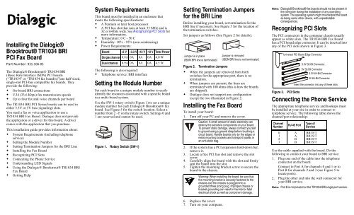
Recognizing <strong>PCI</strong> Slots<br />
The <strong>PCI</strong> connectors in <strong>the</strong> computer chassis usually<br />
appear as white slots. The <strong>TR1034</strong> <strong>BRI</strong> <strong>Fax</strong> <strong>Board</strong><br />
has a <strong>PCI</strong> board edge connector. It can be inserted into<br />
any of <strong>the</strong> <strong>PCI</strong> slots shown in Figure 3.<br />
Figure 3. <strong>PCI</strong> Slots<br />
Connecting <strong>the</strong> Phone Service<br />
The appropriate telephone service and hookups must<br />
be installed at your site in order to connect to<br />
telephone service. The following table shows <strong>the</strong><br />
channel/port relationship:<br />
Channel<br />
Number<br />
0<br />
1<br />
2<br />
3<br />
Universal <strong>PCI</strong> <strong>Board</strong> Edge Connector<br />
RJ-45 Port<br />
A<br />
A BB<br />
3.3V 32-Bit Connector<br />
5V 32-Bit Connector<br />
3.3V 64-Bit Connector<br />
5V 64-Bit Connector<br />
Insert <strong>the</strong> connector into any of <strong>the</strong>se slots.<br />
Type of<br />
Service<br />
<strong>BRI</strong> S/T<br />
<strong>BRI</strong> S/T<br />
<strong>BRI</strong> S/T<br />
<strong>BRI</strong> S/T<br />
Use <strong>the</strong> cable supplied with <strong>the</strong> board. Do <strong>the</strong><br />
following to connect your board to <strong>BRI</strong> service:<br />
1. Plug one end of <strong>the</strong> cable into <strong>the</strong> telephone<br />
connector on <strong>the</strong> board.<br />
Connect to Port A for channels 0 and 1 or to<br />
Port B for channels 2 and 3 (see Figure 5 to<br />
locate ports).<br />
2. Plug <strong>the</strong> o<strong>the</strong>r end into <strong>the</strong> wall connector for<br />
your <strong>BRI</strong> service.<br />
Note: Port B is not present on <strong>the</strong> <strong>TR1034</strong> <strong>BRI</strong> single port version.
Before using your <strong>BRI</strong> service, you must configure<br />
certain parameters. See your software documentation<br />
for details.<br />
See Figure 4 for pinout details for your board:<br />
Figure 4. Connector Pinouts<br />
Understanding LED Signals<br />
LEDs on <strong>the</strong> Mounting Bracket<br />
The LEDs on <strong>the</strong> mounting bracket provide<br />
information about <strong>the</strong> status of <strong>the</strong> different systems<br />
on <strong>the</strong> board. To identify and locate <strong>the</strong>se LEDs, see<br />
Figure 5.<br />
The following tables describe how <strong>the</strong> end panel<br />
LEDs provide information:<br />
<strong>BRI</strong> Status LED<br />
<strong>BRI</strong> LED Meaning<br />
Red Layer 1 is down. This can occur if <strong>the</strong><br />
cable is wired incorrectly or <strong>the</strong> CPE<br />
or CO emulation is wrong.<br />
Yellow Layer 1 is up, but layer 2 is down.<br />
This state can occur if <strong>the</strong> protocol<br />
has not been initialized, <strong>the</strong> D<br />
channel has not been enabled, or <strong>the</strong><br />
clocks have not synchronized.<br />
Green Layer 1 is up, and layer 2 is up.<br />
Red/green The board is currently receiving CRC<br />
errors.<br />
Channel LEDs<br />
Pin<br />
1<br />
2<br />
3<br />
4<br />
5<br />
6<br />
7<br />
8<br />
Channel LEDs Meaning<br />
Port A<br />
No connection<br />
No connection<br />
TX Tip 0<br />
RX Tip 0<br />
RX Ring 0<br />
TX Ring 0<br />
No connection<br />
No connection<br />
Off Channel is idle.<br />
Flashing green Channel is being set up or is<br />
connected.<br />
Port B<br />
No connection<br />
No connection<br />
TX Tip 1<br />
RX Tip 1<br />
RX Ring 1<br />
TX Ring 1<br />
No connection<br />
No connection<br />
<strong>Board</strong> Status LED<br />
<strong>Board</strong> Status LED Meaning<br />
Flashing yellow <strong>Board</strong> is powered up and is<br />
passing self test checks.<br />
Steady red <strong>Board</strong> is powered up, and <strong>the</strong> self<br />
test has failed.<br />
Flashing yellow <strong>Board</strong> is powered up and is<br />
and green downloading firmware.<br />
Flashing green Firmware is downloaded, and <strong>the</strong><br />
board is in service.<br />
Solid green <strong>Board</strong> is hung, needs to be reset.<br />
Flickering red <strong>Board</strong> has failed, needs to be reset.<br />
Off <strong>Board</strong> has no power, or board is<br />
hung and needs to be reset.<br />
Port A<br />
RJ-45 Connector<br />
Port B<br />
RJ-45 Connector<br />
<strong>BRI</strong> Status LEDs<br />
Channel LEDs<br />
<strong>Board</strong> Status LED<br />
Mounting Bracket<br />
Port A ISDN<br />
Termination Jumpers<br />
Figure 5. <strong>Dialogic®</strong> <strong>Brooktrout®</strong> <strong>TR1034</strong> <strong>BRI</strong> <strong>PCI</strong><br />
Series <strong>Fax</strong> <strong>Board</strong><br />
Module Number Switch (SW-1)<br />
<strong>PCI</strong> Connector<br />
Port B ISDN<br />
Termination Jumpers<br />
LEDs on <strong>the</strong> <strong>Dialogic®</strong> <strong>Brooktrout®</strong> <strong>Fax</strong><br />
<strong>Board</strong><br />
The LEDs on <strong>the</strong> board provide information about <strong>the</strong><br />
status of <strong>the</strong> board. To locate <strong>the</strong>se LEDs, see<br />
Figure 5.<br />
The following table describes how <strong>the</strong> LEDs on <strong>the</strong><br />
board provide information:<br />
LED Meaning<br />
Power LED - D10<br />
This graphic displays a Dual <strong>BRI</strong> board.<br />
DSP Displays <strong>the</strong> status for <strong>the</strong> DSP. After <strong>the</strong><br />
firmware is loaded and during normal<br />
execution, this LED blinks about every<br />
second. If <strong>the</strong> LED is not blinking, <strong>the</strong> DSP<br />
firmware is not running.<br />
Power Steady green indicates good board power.<br />
DSP LED - D7<br />
Using <strong>the</strong> <strong>Dialogic®</strong> <strong>Brooktrout®</strong><br />
<strong>TR1034</strong> <strong>BRI</strong> <strong>Fax</strong> <strong>Board</strong><br />
Once you have installed <strong>the</strong> <strong>TR1034</strong> <strong>BRI</strong> <strong>Fax</strong> <strong>Board</strong>, install<br />
and configure your voice or fax software application<br />
according to instructions included with <strong>the</strong> software.<br />
Getting Help<br />
Dialogic provides technical support for customers who have<br />
purchased hardware or software products from Dialogic. If<br />
you purchased products from a reseller, please contact that<br />
reseller for technical support.<br />
This equipment contains no user serviceable parts and is not<br />
intended for repair by unauthorized personnel.<br />
If you experience problems with <strong>the</strong> <strong>TR1034</strong> <strong>BRI</strong> <strong>Fax</strong><br />
<strong>Board</strong>, for repair or warranty information, please use <strong>the</strong><br />
web site below. If <strong>the</strong> equipment is causing harm to <strong>the</strong><br />
telephone network, <strong>the</strong> telephone company might request<br />
that you disconnect <strong>the</strong> equipment until <strong>the</strong> problem is<br />
resolved.<br />
www.dialogic.com/support<br />
Copyright and Legal Notice<br />
Copyright © 2006-2008] Dialogic Corporation. All Rights Reserved. You may not<br />
reproduce this document in whole or in part without permission in writing from Dialogic<br />
Corporation at <strong>the</strong> address provided below.<br />
All contents of this document are subject to change without notice and do not represent a<br />
commitment on <strong>the</strong> part of Dialogic Corporation or its subsidiaries. Reasonable effort is<br />
made to ensure <strong>the</strong> accuracy of <strong>the</strong> information contained in <strong>the</strong> document. However, due<br />
to ongoing product improvements and revisions, Dialogic Corporation and its subsidiaries<br />
do not warrant <strong>the</strong> accuracy of this information and cannot accept responsibility for errors<br />
or omissions that may be contained in this document.<br />
INFORMATION IN THIS DOCUMENT IS PROVIDED IN CONNECTION WITH<br />
DIALOGIC® PRODUCTS. NO LICENSE, EXPRESS OR IMPLIED, BY ESTOPPEL OR<br />
OTHERWISE, TO ANY INTELLECTUAL PROPERTY RIGHTS IS GRANTED BY THIS<br />
DOCUMENT. EXCEPT AS EXPLICITLY SET FORTH BELOW OR AS PROVIDED IN A<br />
SIGNED AGREEMENT BETWEEN YOU AND DIALOGIC, DIALOGIC ASSUMES NO<br />
LIABILITY WHATSOEVER, AND DIALOGIC DISCLAIMS ANY EXPRESS OR IMPLIED<br />
WARRANTY, RELATING TO SALE AND/OR USE OF DIALOGIC PRODUCTS<br />
INCLUDING LIABILITY OR WARRANTIES RELATING TO FITNESS FOR A<br />
PARTICULAR PURPOSE, MERCHANTABILITY, OR INFRINGEMENT OF ANY<br />
INTELLECTUAL PROPERTY RIGHT OF A THIRD PARTY.<br />
Dialogic products are not intended for use in medical, life saving, life sustaining, critical<br />
control or safety systems, or in nuclear facility applications.<br />
It is possible that <strong>the</strong> use or implementation of any one of <strong>the</strong> concepts, applications, or<br />
ideas described in this document, in marketing collateral produced by or on web pages<br />
maintained by Dialogic Corporation or its subsidiaries may infringe one or more patents or<br />
o<strong>the</strong>r intellectual property rights owned by third parties. Dialogic Corporation or its<br />
subsidiaries do not provide any intellectual property licenses with <strong>the</strong> sale of Dialogic<br />
products o<strong>the</strong>r than a license to use such product in accordance with intellectual property<br />
owned or validly licensed by Dialogic Corporation or its subsidiaries. More detailed<br />
information about such intellectual property is available from Dialogic Corporation's legal<br />
department at 9800 Cavendish Blvd., 5th Floor, Montreal, Quebec, Canada H4M 2V9.<br />
The software referred to in this document is provided under a Software License<br />
Agreement. Refer to <strong>the</strong> Software License Agreement for complete details governing <strong>the</strong><br />
use of <strong>the</strong> software.<br />
Dialogic Corporation encourages all users of its products to procure all necessary<br />
intellectual property licenses required to implement any concepts or applications and does<br />
not condone or encourage any intellectual property infringement and disclaims any<br />
responsibility related <strong>the</strong>reto. These intellectual property licenses may differ from country<br />
to country and it is <strong>the</strong> responsibility of those who develop <strong>the</strong> concepts or applications to<br />
be aware of and comply with different national license requirements.<br />
Dialogic, Dialogic Pro, Brooktrout, Cantata, SnowShore, Eicon, Eicon Networks,<br />
Eiconcard, Diva, SIPcontrol, Diva ISDN, Tru<strong>Fax</strong>, Realblocs, Realcomm 100, NetAccess,<br />
Instant ISDN, TRXStream, Exnet, Exnet Connect, EXS, ExchangePlus VSE, Switchkit,<br />
N20, Powering The Service-Ready Network, Vantage, Connecting People to Information,<br />
Connecting to Growth and Shiva, among o<strong>the</strong>rs as well as related logos, are ei<strong>the</strong>r<br />
registered trademarks or trademarks of Dialogic.<br />
Dialogic Corporation © 1998–2008