Capnographic Waveforms in the Mechanically Ventilated Patient
Capnographic Waveforms in the Mechanically Ventilated Patient
Capnographic Waveforms in the Mechanically Ventilated Patient

Create successful ePaper yourself
Turn your PDF publications into a flip-book with our unique Google optimized e-Paper software.
CAPNOGRAPHIC WAVEFORMS IN THE MECHANICALLY VENTILATED PATIENT<br />
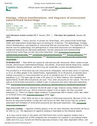
Fig. 8. Acute change <strong>in</strong> capnogram from normal (shaded area).<br />
The endotracheal tube was <strong>in</strong> <strong>the</strong> right ma<strong>in</strong> bronchus.<br />
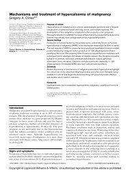
Fig. 9. Capnogram from a patient undergo<strong>in</strong>g chest compressions.<br />
Note that <strong>the</strong> capnogram curve changes at <strong>the</strong> po<strong>in</strong>t at which a<br />
“fresh” (less tired) cl<strong>in</strong>ician (assistant) took over <strong>the</strong> chest compressions.<br />
(Adapted from Reference 42, with permission.)<br />
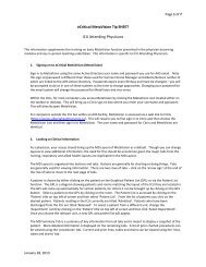
Fig. 10. Capnogram dur<strong>in</strong>g successive stages of cardiopulmonary<br />
resuscitation, with (A) return of spontaneous circulation. The arrow<br />
labeled NaHCO 3 <strong>in</strong>dicates <strong>the</strong> po<strong>in</strong>t at which sodium bicarbonate<br />
was adm<strong>in</strong>istered. (Adapted from Reference 43, with permission.)<br />
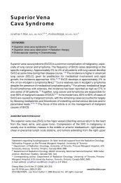
Fig. 11. Capnogram dur<strong>in</strong>g cardiac arrest with rebreath<strong>in</strong>g.<br />
pleted <strong>the</strong> procedure. Rapid recognition of changes <strong>in</strong> ETT<br />
placement can also avoid o<strong>the</strong>r problems, such as desaturation.<br />
However, though <strong>the</strong> presence of CO 2 <strong>in</strong> <strong>the</strong> ETT<br />
<strong>in</strong>creases confidence that <strong>the</strong> ETT is properly placed, it<br />
does not assure that it is properly placed. Endobronchial<br />
<strong>in</strong>tubation can have a normal-appear<strong>in</strong>g capnogram. Proper<br />
Fig. 12. Capnogram <strong>in</strong>dicat<strong>in</strong>g a flutter<strong>in</strong>g expiratory valve with<br />
rebreath<strong>in</strong>g (A). (Adapted from Reference 44, with permission.)<br />
ETT placement should be confirmed with multiple techniques.<br />
36<br />
As <strong>the</strong> lack of CO 2 is used to determ<strong>in</strong>e improper ETT<br />
placement, <strong>the</strong> presence of CO 2 is <strong>in</strong>creas<strong>in</strong>gly be<strong>in</strong>g used<br />
to identify improper nasogastric or oral feed<strong>in</strong>g-tube placement.<br />
37–41<br />
Cardiopulmonary Resuscitation<br />
Capnography has long been used for rapid evaluation of<br />
<strong>the</strong> effectiveness of chest compressions. 42 CO 2 removal is<br />
more effective when a less fatigued person performs <strong>the</strong><br />
cardiopulmonary resuscitation (Fig. 9). Falk et al 43 found<br />
changes <strong>in</strong> CO 2 removal dur<strong>in</strong>g successive stages of cardiopulmonary<br />
resuscitation (Fig. 10). This <strong>in</strong>cluded <strong>the</strong><br />
adm<strong>in</strong>istration of sodium bicarbonate, result<strong>in</strong>g <strong>in</strong> <strong>the</strong> byproduct<br />
of CO 2 and <strong>the</strong> successful return to spontaneous<br />
circulation, shown as a dramatic <strong>in</strong>crease <strong>in</strong> CO 2 removal.<br />
A mechanical problem dur<strong>in</strong>g cardiopulmonary resuscitation<br />
can be quickly recognized with <strong>the</strong> aid of a capnogram.<br />
Figure 11 illustrates a cl<strong>in</strong>ical situation <strong>in</strong> which <strong>the</strong><br />
flow to a non-self-<strong>in</strong>flat<strong>in</strong>g resuscitation bag was set too<br />
low, so <strong>the</strong> CO 2 was not be<strong>in</strong>g adequately washed out of<br />
<strong>the</strong> bag and <strong>the</strong>re was excessive rebreath<strong>in</strong>g of CO 2, which<br />
was identified via <strong>the</strong> capnogram. The flow was <strong>in</strong>creased<br />
and CO 2 returned to basel<strong>in</strong>e.<br />
Mechanical Ventilation<br />
A paper by Carlon et al <strong>in</strong>cluded a wide range of capnographic<br />
waveforms from mechanically ventilated patients,<br />
44 which supported <strong>the</strong> view that capnography assists<br />
<strong>in</strong> quickly identify<strong>in</strong>g and resolv<strong>in</strong>g cl<strong>in</strong>ical and<br />
technical problems. We will discuss several of <strong>the</strong> capnograms<br />
from that paper.<br />
Figure 12 illustrates <strong>the</strong> capnogram pattern from a flutter<strong>in</strong>g<br />
expiratory valve, which can be caused by water<br />
condensation or pressure compensation by <strong>the</strong> ventilator.<br />
Note that some rebreath<strong>in</strong>g is present.<br />
Figure 13 illustrates conflict between mandatory breaths<br />
(ie, delivered by <strong>the</strong> ventilator) and spontaneous breaths<br />
(ie, <strong>the</strong>re was patient-ventilator asynchrony dur<strong>in</strong>g <strong>in</strong>termittent<br />
mandatory ventilation).<br />
RESPIRATORY CARE • JANUARY 2005 VOL 50 NO 1 103