Flic® Laser Bar Code Scanner Developer's Guide - Dr. Vogt GmbH
Flic® Laser Bar Code Scanner Developer's Guide - Dr. Vogt GmbH
Flic® Laser Bar Code Scanner Developer's Guide - Dr. Vogt GmbH

You also want an ePaper? Increase the reach of your titles
YUMPU automatically turns print PDFs into web optimized ePapers that Google loves.
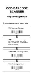
Flic ® <strong>Laser</strong> <strong>Bar</strong> <strong>Code</strong> <strong>Scanner</strong><br />
Developer’s <strong>Guide</strong><br />
Document: DA0110468 Rev A
Trademarks<br />
Microvision, the Microvision logo, and Flic are registered trademarks of Microvision, Inc.<br />
Flicware is a trademark of Microvision, Inc.<br />
Windows is a trademark of Microsoft Corporation.
DA0110468 Rev A Flic ® <strong>Laser</strong> <strong>Bar</strong> <strong>Code</strong> <strong>Scanner</strong> Developer’s <strong>Guide</strong><br />
Table of Contents<br />
1 Getting Started 5<br />
1.1 Developer Options 5<br />
1.2 Determining the Version of Firmware Installed on Your <strong>Scanner</strong> 5<br />
1.3 Firmware Version History 6<br />
1.3.1 Changes in Version 1.8.0 6<br />
1.3.2 Changes in Version 1.7.0 7<br />
1.3.3 Changes in Version 1.6.0 7<br />
1.4 Customer Support 7<br />
2 The Flic <strong>Scanner</strong>’s Device Features 8<br />
2.1 Visual and Audio Scan Status Indicators 8<br />
2.2 Standby Power Save Mode 8<br />
2.3 Flic ID and Data Features 8<br />
2.4 Operation Modes 9<br />
2.5 <strong>Bar</strong> <strong>Code</strong> Data Storage 10<br />
2.6 Device Configuration Data 11<br />
2.6.1 Device Configuration Bytes and Bits 12<br />
3 Data Formats 16<br />
3.1 Compatible Data Format 16<br />
3.2 XML Data Format 17<br />
3.2.1 XML Tags and Attributes 17<br />
3.2.2 XML Format Features 18<br />
4 Configuring the Flic <strong>Scanner</strong> 19<br />
5 Communicating with the Flic <strong>Scanner</strong> 19<br />
5.1 Setting Up HyperTerminal 19<br />
5.2 Programming Conventions 21<br />
5.3 Sending Commands to the Flic <strong>Scanner</strong> 21<br />
5.3.1 Standby Mode 21<br />
5.4 Command <strong>Code</strong>s 22<br />
5.4.1 Wake Command 23<br />
5.4.2 Who Command 23<br />
5.4.3 Signal Command 23<br />
5.4.4 Set Device Configuration Command 24<br />
5.4.5 Return to Factory Settings Command 24<br />
5.4.6 Initialize Time Reference Setting Command 25<br />
5.4.7 Download <strong>Bar</strong> <strong>Code</strong> Data Command 25<br />
5.4.8 Clear <strong>Bar</strong> <strong>Code</strong> Data Command 26<br />
6 Examples 27<br />
6.1 Changing the <strong>Scanner</strong>’s Configuration 27<br />
6.2 Changing the Download Data Format to XML 27<br />
6.3 Changing Multiple Consecutive Bytes 27<br />
6.4 Disabling Automatic Data Download 28<br />
6.5 Setting NCR Default Values 28<br />
6.6 Writing a Number to the User ID Field 28<br />
6.7 Writing an 8-Character String to the User ID Field 29<br />
6.8 Recovering the Time From a Timestamp 29<br />
6.9 Transmitting Supplemental <strong>Bar</strong> <strong>Code</strong>s 30<br />
9/29/2003 Page 3
DA0110468 Rev A Flic ® <strong>Laser</strong> <strong>Bar</strong> <strong>Code</strong> <strong>Scanner</strong> Developer’s <strong>Guide</strong><br />
7 Appendices 32<br />
7.1 Cable Pin Out 32<br />
7.2 COM Port Settings 32<br />
7.3 Microvision and NCR Default Values 33<br />
7.4 AIM Symbol <strong>Code</strong>s 34<br />
7.4.1 AIM <strong>Code</strong> Modifiers 34<br />
7.5 <strong>Bar</strong> <strong>Code</strong>s 35<br />
7.5.1 Device Option Control <strong>Bar</strong> <strong>Code</strong>s 35<br />
7.5.2 Symbology Selection Control <strong>Bar</strong> <strong>Code</strong>s 37<br />
7.5.3 Supplemental <strong>Bar</strong> <strong>Code</strong>s 38<br />
7.5.4 Symbology Options Control <strong>Bar</strong> <strong>Code</strong>s 39<br />
7.5.5 Command Control <strong>Bar</strong> <strong>Code</strong>s 39<br />
7.6 ASCII Chart 40<br />
List of Tables<br />
Table 1: LED and Beeper Signals 8<br />
Table 2: Flic <strong>Scanner</strong> Features 8<br />
Table 3: Flic Operation Modes and Data Formats 10<br />
Table 4: Device Configuration Data 11<br />
Table 5: Configuration of First Byte (Address 08) 12<br />
Table 6: Configuration of Second Byte (Address 09) 13<br />
Table 7: Configuration of Third Byte (Address 0A) 14<br />
Table 8: Configuration of Fourth Byte (Address 0B) 15<br />
Table 9: XML Tags and Attributes 17<br />
Table 10: Command <strong>Code</strong>s 22<br />
Table 11: T Command <strong>Code</strong>s Options 24<br />
Table 12: Default Settings Options 25<br />
Table 13: How Data is Downloaded and Deleted from Memory in Batch Mode 26<br />
Table 14: AIM <strong>Code</strong> 34<br />
Table 15: <strong>Code</strong> 39 Modifiers 34<br />
Table 16: <strong>Code</strong> 128 Modifiers 34<br />
Table 17: UPC/EAN Modifiers 34<br />
List of Figures<br />
Figure 1: Cable Pin Out 32<br />
9/29/2003 Page 4
DA0110468 Rev A Flic ® <strong>Laser</strong> <strong>Bar</strong> <strong>Code</strong> <strong>Scanner</strong> Developer’s <strong>Guide</strong><br />
1 Getting Started<br />
The Flic <strong>Laser</strong> <strong>Bar</strong> <strong>Code</strong> <strong>Scanner</strong> is a flexible product that supports both new and existing applications. The<br />
Flic’s flexibility makes it ideal for a wide range of data collection applications. For portable applications such<br />
as asset tracking, the Flic scanner can store a minimum of 500 UPC bar codes in memory. The saved bar<br />
codes can be easily downloaded for processing. For tethered uses such as library or wired network<br />
applications, the Flic can be attached to a host for immediate data entry. If you require a little of both, Flic<br />
can operate tethered and then be removed and used in store-and-forward (“batch”) mode for applications<br />
like healthcare, where it might be easier to bring the scanner to the patient rather than the patient to the<br />
scanner.<br />
The Flic scanner supports two transmission modes, tethered or store-and-forward, and two data formats,<br />
legacy compatible and XML:<br />
• When the Flic scanner is attached to a computer or other host, it is tethered. In this mode, when<br />
the user presses the button, the scanner immediately transmits the decoded bar code to the host.<br />
• When the Flic scanner is not attached to a host, it operates in batch mode. In this mode, when the<br />
user presses the button, the scanner stores the decoded bar code. Then when the user attaches<br />
the scanner to the host, the scanner immediately begins downloading the stored bar codes.<br />
• The compatible data format allows the Flic scanner to work with legacy systems. Therefore, you do<br />
not need to change your existing applications.<br />
• The XML data format gives access to the enhanced features of the scanner, such as timestamp,<br />
device and user IDs. It supports PC- and web-based applications.<br />
1.1 Developer Options<br />
Microvision provides three ways for you, a developer, to interact with the Flic scanner:<br />
1. The FlicwareTM and FlicwareTM Pro applications. These are Windows® based applications that run in<br />
the background. They convert the data from a scanner that is connected to a USB or serial port<br />
into keystrokes. Then they insert the keystrokes at the current cursor position into the active<br />
application.<br />
o The basic version of the application, FlicwareTM, turns any Windows ® program into a bar<br />
code application in only minutes. You can download FlicwareTM for free from the<br />
www.flicscanner.com website, or you can order the software on a CD. The CD also<br />
provides USB drivers for the scanner.<br />
o The upgrade version, FlicwareTM Pro, provides enhancements such as transaction<br />
processing, application recognition and sound prompting. It allows you to customize the<br />
interface. FlicwareTM Pro can be purchased from the website, or from your local reseller.<br />
2. A web browser plug-in. Microvision provides a browser plug-in that handles the setup and<br />
communication with the Flic scanner. The plug-in passes XML formatted data to the web page. The<br />
plug-in and the documentation are available from customer support. Contact customer support at<br />
customer_service@microvision.com.<br />
3. The device interface defined in this developer guide supports full, customized programming.<br />
1.2 Determining the Version of Firmware Installed on Your <strong>Scanner</strong><br />
With each firmware release Microvision has implemented new features to enhance the Flic scanner. To see<br />
what features were implemented in what release version, see “1.3 Firmware Version History” below.<br />
9/29/2003 Page 5
DA0110468 Rev A Flic ® <strong>Laser</strong> <strong>Bar</strong> <strong>Code</strong> <strong>Scanner</strong> Developer’s <strong>Guide</strong><br />
Note: In this guide, features that have been implemented after firmware version 1.5.0 are denoted by a<br />
FWV code, followed by the implementation version number.<br />
This section tells you one way of determining what version of the firmware is installed on your scanner. You<br />
can also use the Who command to find this information. The Who command is documented in “5.4.2 Who<br />
Command” on page 23.<br />
Note: The scanner’s firmware cannot be upgraded. If you need to use the functionality that is implemented<br />
in a later version, please contact Microvision.<br />
To determine the firmware version installed on your scanner:<br />
1. Start the Flicware application by selecting Start > Programs > Microvision > Flicware.<br />
1. From the Tools menu, select Options…<br />
2. On the Options dialog box, if the port to which you connected the scanner is different than the<br />
port that is displayed, select the appropriate port from the Port: drop down menu.<br />
Note: Once the software for the USB adaptor has been installed, the scanner treats USB as if it was<br />
a COM port.<br />
3. Click Test.<br />
4. The application detects the Flic scanner and displays the following information:<br />
Look for the number in the FW field. This is the firmware version number.<br />
1.3 Firmware Version History<br />
In this guide, features that have been implemented after firmware version 1.5.0 are denoted by a FWV<br />
code, followed by the implementation version number. The version changes are summarized below.<br />
1.3.1 Changes in Version 1.8.0<br />
• Implemented expansion of UPC-A bar codes to EAN-13 format. If both the expand UPC-E codes<br />
(byte 09, bit 4) and the convert UPC-A codes (byte 0B, bit 2) are enabled, then the scanner will<br />
expand all UPC-E codes to the EAN-13 format.<br />
• Implemented standard vs. aggressive scanning selectability via control bar code. Standard scanning<br />
meets all UPC scanning specifications. Aggressive scanning ignores the UPC/EAN-13 requirement<br />
for the amount of blank space (quiet zone) that should surround a bar code.<br />
9/29/2003 Page 6
DA0110468 Rev A Flic ® <strong>Laser</strong> <strong>Bar</strong> <strong>Code</strong> <strong>Scanner</strong> Developer’s <strong>Guide</strong><br />
1.3.2 Changes in Version 1.7.0<br />
• Changed the NCR symbology identifiers for <strong>Code</strong> 39 and <strong>Code</strong> 128.<br />
• Implemented combined bar code feature for supplemental bar codes. For more information, see<br />
“6.9 Transmitting Supplemental <strong>Bar</strong> <strong>Code</strong>s” on page 30.<br />
• Implemented selectable baud rates, 4800 and 9600.<br />
1.3.3 Changes in Version 1.6.0<br />
• Changed the inter-bar code delay to have four selectable settings: no delay, 500ms, 1.1s and 1.6s.<br />
• Added support for supplemental bar codes with EAN-8.<br />
• Changed how the scanner appends supplemental bar codes to the base bar code when using NCR<br />
identifiers.<br />
1.4 Customer Support<br />
Website: www.flicscanner.com<br />
Email: customer_service@microvision.com<br />
Phone: Toll free within the United States: (866) 333-3542<br />
International: (425) 354-3542<br />
9/29/2003 Page 7
DA0110468 Rev A Flic ® <strong>Laser</strong> <strong>Bar</strong> <strong>Code</strong> <strong>Scanner</strong> Developer’s <strong>Guide</strong><br />
2 The Flic <strong>Scanner</strong>’s Device Features<br />
2.1 Visual and Audio Scan Status Indicators<br />
The Flic scanner has a green LED and a piezo beeper to provide visual and audible indicators of the status of<br />
a scan. The combination of the two indicates various device conditions as shown in the table below. By<br />
default, both the LED and beeper are enabled. Either the LED or the beeper can be turned on or off by<br />
using the bar codes listed in “7.5.1 Device Option Control <strong>Bar</strong> <strong>Code</strong>s” in the Appendices on page 35, or by<br />
setting the appropriate control bits through the command interface.<br />
Table 1: LED and Beeper Signals<br />
Green LED Beeper<br />
Good Scan On for 200 msec. Single beep, higher pitch than the<br />
Invalid Command beep.<br />
Device Memory Full Blinks 3 times. Beeps 3 times.<br />
Downloading Blinks 2 times per second while the<br />
data is downloading.<br />
None.<br />
Download Complete On for 300 msec. Three beeps that descend in pitch.<br />
Invalid Command Not Used. Single beep, lower pitch than the<br />
Good Scan beep.<br />
System Error Not Used. Beeps 5 times. This cannot be disabled.<br />
2.2 Standby Power Save Mode<br />
The Flic scanner operates from 3 AAA batteries that will supply over 20,000 scans. In order to conserve<br />
power the scanner enters standby mode after two seconds of no activity. When scanning, the device wakes<br />
up when you press the scan button. When communicating with a host, the host must follow the wake-up<br />
sequence described in “5.4.1 Wake Command” on page 23.<br />
2.3 Flic ID and Data Features<br />
The following information can be configured for each Flic scanner. Except for the Time Reference field, the<br />
configuration information is stored in non-volatile memory. The Time Reference data is stored in RAM.<br />
Flic Feature Description<br />
Table 2: Flic <strong>Scanner</strong> Features<br />
Device ID Each device has a unique ID number. This number is set at the factory, and it<br />
cannot be changed. You can use this feature to associate a particular scanner with a<br />
specific application or user.<br />
User ID You can use this data field to store custom information. This field is targeted to be<br />
used as a user ID but can be used to store any information. For example, you can<br />
use it to store the employee number, application data, or the installation date. For<br />
more information, see “6.6 Writing a Number to the User ID Field” on page 28,<br />
and “6.7 Writing an 8-Character String to the User ID Field” on page 29.<br />
9/29/2003 Page 8
DA0110468 Rev A Flic ® <strong>Laser</strong> <strong>Bar</strong> <strong>Code</strong> <strong>Scanner</strong> Developer’s <strong>Guide</strong><br />
Flic Feature Description<br />
Symbology ID Each bar code scanned is associated with a code that identifies the bar code<br />
symbology of the data. This data can optionally be transmitted as part of the bar<br />
code data record in either Compatible or XML format. The scanner supports AIM<br />
and NCR code symbology identifiers. For more information, see the bar codes in<br />
“7.5 <strong>Bar</strong> <strong>Code</strong>s” on page 35, and the “2.6 Device Configuration Data” on page 11.<br />
Timestamp This feature provides the amount of time elapsed since the last scan. You can<br />
choose whether to store the relative timestamp with each successful bar code, or<br />
with each button push. For more information, see “2.6 Device Configuration Data”<br />
on page 11.<br />
You can use the timestamp to track time and attendance or for any application<br />
where the scanning time is important information.<br />
Note: This information is not retained if the scanner loses power, or if you return<br />
the scanner to its default configuration.<br />
Time Reference Use this data field to store an initial time reference value. The timestamp associated<br />
with each scan is the amount of time from the last scan. Your application can use<br />
the value of this field to calculate the actual time by adding it and the amount of<br />
time from the last scan. For more information, see “5.4.6 Initialize Time Reference<br />
Setting Command” on page 25, and “6.8 Recovering the Time From a Timestamp”<br />
on page 29.<br />
If you do not need to calculate time values, you can use this field to store other<br />
information.<br />
2.4 Operation Modes<br />
Note: The information in this field is stored in RAM. It is not retained if the scanner<br />
loses power, or if you return the scanner ‘s configuration to the default values.<br />
The Flic scanner can be used in either real-time tethered mode or store-and-forward batch mode. The<br />
scanner runs in tethered mode when the cable is plugged into the scanner. When the cable is not plugged<br />
in, the scanner operates in batch mode. The scanner automatically detects if the cable is plugged in.<br />
When tethered, the scanner operates like a traditional scanner and transmits the scanned data immediately<br />
after the scan. In batch mode, the data is stored in memory until the memory is full. The stored data can<br />
then be automatically transmitted to the host when the device is plugged in or it can be stored until the<br />
host sends a request for the data.<br />
The scanner can transfer data in the Compatible or XML formats. The Compatible data format allows the<br />
Flic scanner to work in legacy systems. You can use ACK/NAK handshaking with the Compatible format to<br />
insure data security. The XML mode supports PC- and web-based applications. For more information, see<br />
“3 Data Formats” on page 16.<br />
9/29/2003 Page 9
DA0110468 Rev A Flic ® <strong>Laser</strong> <strong>Bar</strong> <strong>Code</strong> <strong>Scanner</strong> Developer’s <strong>Guide</strong><br />
Table 3: Flic Operation Modes and Data Formats<br />
Mode ACK/NAK Tethered Batch<br />
Compatible<br />
(default)<br />
Enabled <strong>Scanner</strong> sends data immediately<br />
after the scan. Host sends .<br />
<strong>Scanner</strong> deletes data after receiving<br />
.<br />
If the scanner receives a , it<br />
retransmits the data up to two<br />
times.<br />
If the scanner does not receive an<br />
, the scanner stores the data<br />
in non-volatile memory. On each<br />
successful scan, the first data record<br />
stored in memory is sent. This<br />
record may not correspond to the<br />
most recent data scanned.<br />
Disabled <strong>Scanner</strong> sends data immediately<br />
after the scan. <strong>Scanner</strong> deletes data.<br />
Warning: If the host software is not<br />
active, the data will be lost.<br />
XML N/A <strong>Scanner</strong> stores data in memory and<br />
sends the data immediately. Host<br />
sends and Clear command.<br />
<strong>Scanner</strong> deletes data when it<br />
receives the Clear command.<br />
If the scanner does not receive the<br />
Clear command, the data remains<br />
in memory and will be<br />
retransmitted with the next scan.<br />
<strong>Scanner</strong> sends the first data record<br />
saved in memory when the cable is<br />
plugged in. Host sends .<br />
<strong>Scanner</strong> deletes data after receiving<br />
. Then the scanner sends<br />
the next record, if one exists.<br />
If the scanner receives a , it<br />
retransmits the data up to two<br />
times.<br />
If the scanner does not receive an<br />
, it saves the data in nonvolatile<br />
memory, and it aborts the<br />
download process.<br />
<strong>Scanner</strong> sends data when the cable<br />
is plugged in. All of the records are<br />
sequentially transmitted and then<br />
deleted from memory.<br />
Warning: If the host software is not<br />
active, the data will be lost.<br />
<strong>Scanner</strong> sends data when the cable<br />
is plugged in. Host sends <br />
and Clear command. <strong>Scanner</strong><br />
deletes data when it receives the<br />
Clear command.<br />
If the scanner does not receive the<br />
Clear command, the data remains in<br />
memory and will be retransmitted<br />
with the next data download.<br />
If you have enabled the timestamp<br />
feature, then the host should reset<br />
the time reference.<br />
2.5 <strong>Bar</strong> <strong>Code</strong> Data Storage<br />
In batch mode, the Flic scanner stores the bar code information in its internal non-volatile memory. The Flic<br />
can store a minimum of 500 UPC bar codes. Since <strong>Code</strong> 39 and <strong>Code</strong> 128 have variable length data, the<br />
minimum number will vary for these bar codes. You can mix bar code styles without penalty.<br />
When the scanner’s memory is full, the scanner’s LED will blink three times, and the beeper will sound three<br />
times. This is the Device Full alert. Once full, the scanner cannot perform any additional scans. If the user<br />
tries to scan by pushing the button, the Flic scanner will repeat the Device Full alert without activating the<br />
laser. In order to enable further scans, you must clear the bar code memory. For information on clearing the<br />
9/29/2003 Page 10
DA0110468 Rev A Flic ® <strong>Laser</strong> <strong>Bar</strong> <strong>Code</strong> <strong>Scanner</strong> Developer’s <strong>Guide</strong><br />
memory, see “5.4.7 Download <strong>Bar</strong> <strong>Code</strong> Data Command” on page 25, and “5.4.8 Clear <strong>Bar</strong> <strong>Code</strong> Data<br />
Command” on page 26.<br />
2.6 Device Configuration Data<br />
This section describes the device configuration bits. The table below shows the data that the scanner stores,<br />
and the memory locations of the data. Since all data values in the scanner are formatted in hexadecimal, the<br />
start and stop memory addresses listed below are in hexadecimal. The data is stored as two characters per<br />
byte, with each character giving the value of a nibble.<br />
Table 4: Device Configuration Data<br />
Description Size Start Memory<br />
Address (ASCII)<br />
Stop Memory<br />
Address (ASCII)<br />
User ID Data 8 bytes 0 7 R/W<br />
Device Configuration Setup 4 bytes 8 B R/W<br />
Device ID 4 bytes C F R<br />
Hardware Version 2 bytes 10 11 R<br />
Firmware Version 3 bytes 12 14 R<br />
Read/Write<br />
Access<br />
For information on the User ID Data, see “6.6 Writing a Number to the User ID Field” on page 28, and<br />
“6.7 Writing an 8-Character String to the User ID Field” on page 29. The section below gives more<br />
information on the Device Configuration Setup. The Device ID, Hardware Version and Firmware Version<br />
fields are factory defined.<br />
For information about the features added in each firmware upgrade, see “1.3 Firmware Version History” on<br />
page 6.<br />
9/29/2003 Page 11
DA0110468 Rev A Flic ® <strong>Laser</strong> <strong>Bar</strong> <strong>Code</strong> <strong>Scanner</strong> Developer’s <strong>Guide</strong><br />
2.6.1 Device Configuration Bytes and Bits<br />
Tables 5, to 8 give the definitions of the bits of each byte in the Device Configuration Setup memory.<br />
Table 5: Configuration of First Byte (Address 08)<br />
Bit Description Values<br />
0 Beep. Enable or disable the beeper. 0 – Off<br />
1 – On* #<br />
2 and 1 Timestamp. Enable or disable setting timestamps for each decoded bar 00 – Off*<br />
code or for any button press even without a decoded bar code. The<br />
timestamp is a relative time difference calculated from the last scan or<br />
button press, depending on the mode.<br />
The timestamp only can be accessed in XML mode. The time stamp data<br />
is transmitted as the DT (delta time) attribute. The timestamp value is a<br />
maximum of 4-bytes, with each count representing one second. Leading<br />
zero bytes will not be transmitted. The host is also responsible for setting<br />
the initial time reference value using the I command. For more<br />
information, see “5.4.6 Initialize Time Reference Setting Command” on<br />
page 25, and “6.8 Recovering the Time From a Timestamp” on page 29.<br />
#<br />
01 – On, timestamp<br />
decoded bar codes<br />
only<br />
10 – On, timestamp<br />
any button press<br />
11 – Off. This is<br />
saved in memory as<br />
00<br />
Warning: When switching time stamp modes, the bar code information<br />
stored in the device’s memory can be corrupted. Therefore, you should<br />
download all data before changing the configuration.<br />
3 LED. Enable or disable the LED indicator. 0 – Off<br />
1 – On* #<br />
4 STX. Enable or disable sending the prefix character in<br />
0 – Off<br />
Compatible format.<br />
#<br />
1 – On*<br />
5 AIM <strong>Code</strong>. Enable or disable transmission of AIM <strong>Code</strong> in both 0 – Off*<br />
Compatible and XML formats. See the AIM code definitions in “7.4 AIM<br />
Symbol <strong>Code</strong>s” on page 34.<br />
This field works in combination with the Enable Combined <strong>Bar</strong> <strong>Code</strong>s,<br />
and the NCR Symbol Identifiers settings. For more information, see “6.9<br />
Transmitting Supplemental <strong>Bar</strong> <strong>Code</strong>s” on page 30.<br />
#<br />
1 – On<br />
6 Linefeed. Enable or disable sending the linefeed character, , after 0 – Off<br />
each carriage return, , in both Compatible and XML formats.<br />
#<br />
1 – On*<br />
7 Acknowledgment Protocol. Enable or disable the ACK/NAK protocol in 0 – Off*<br />
Compatible format. This does not affect XML format.<br />
#<br />
1 – On<br />
* Factory Default Setting<br />
# NCR Factory Default Setting<br />
9/29/2003 Page 12
DA0110468 Rev A Flic ® <strong>Laser</strong> <strong>Bar</strong> <strong>Code</strong> <strong>Scanner</strong> Developer’s <strong>Guide</strong><br />
Table 6: Configuration of Second Byte (Address 09)<br />
Bit Description Values<br />
0 Download Format. Set the data transmission format for scanner. 0 – Compatible* #<br />
1 ETX Enable. Enable or disable replacing the or line<br />
termination characters with the character.<br />
2 Disable Auto-Download. Enable or disable automatically downloading<br />
the bar code data when the scanner detects the cable being plugged in.<br />
When automatic data download is disabled, the host must issue a D<br />
command to tell the scanner to send the data. For more information, see<br />
“5.4.7 Download <strong>Bar</strong> <strong>Code</strong> Data Command” on page 25.<br />
3 NCR Symbol Identifiers. Enable or disable using NCR symbol identifiers.<br />
The identifier is a one or two character string that precedes each bar<br />
code. When you enable this bit, you must disable AIM codes because the<br />
AIM codes have higher precedence.<br />
When enabled, the transmitted bar code will be prefixed with a letter<br />
that identifies the bar code’s symbology:<br />
<strong>Code</strong> A E F FF a f<br />
Symbology UPC-A UPC-E EAN-<br />
13<br />
EAN-8 <strong>Code</strong><br />
39<br />
<strong>Code</strong><br />
128<br />
This field works in combination with the AIM <strong>Code</strong>, and the Enable<br />
Combined <strong>Bar</strong> <strong>Code</strong>s settings. For more information, see “6.9<br />
Transmitting Supplemental <strong>Bar</strong> <strong>Code</strong>s” on page 30.<br />
4 Expand UPC-E <strong>Code</strong>s (FWV 1.8.0). Enable or disable expanding UPC-E<br />
codes to the equivalent UPC-A code.<br />
1 – XML<br />
0 – Off* #<br />
1 – On<br />
0 – Enable<br />
automatic data<br />
download* #<br />
1 – Disable<br />
automatic data<br />
download<br />
0 – Off*<br />
1 – On #<br />
0 – Do not<br />
expand* #<br />
1 – Expand<br />
5 Reserved. 0<br />
6 <strong>Code</strong> 39 Strip Check Character. Enable or disable stripping the 0 – Off*<br />
checksum character from the data. When enabled, the scanner will force<br />
checksum verification regardless of the setting of the <strong>Code</strong> 39 Checksum<br />
bit.<br />
#<br />
1 – On<br />
7 <strong>Code</strong> 39 Checksum. Enable or disable verifying the checksum before 0 – Off*<br />
storing the data.<br />
#<br />
1 – On<br />
* Factory Default Setting<br />
# NCR Factory Default Setting<br />
9/29/2003 Page 13
DA0110468 Rev A Flic ® <strong>Laser</strong> <strong>Bar</strong> <strong>Code</strong> <strong>Scanner</strong> Developer’s <strong>Guide</strong><br />
The bits defined in Table 7 are used to disable individual bar code symbology identifiers or to configure<br />
supplemental data. All of the disable bits are set to 0 by default, meaning the code is not disabled, that is, it<br />
is enabled. When these bits are set to 1, the corresponding symbology is disabled.<br />
Table 7: Configuration of Third Byte (Address 0A)<br />
Bit Description Values<br />
0 Disable <strong>Code</strong> 39 0 – Off* #<br />
1 – On<br />
1 Disable <strong>Code</strong> 128 0 – Off* #<br />
1 – On<br />
2 Disable UPC-E 0 – Off* #<br />
1 – On<br />
3 Disable EAN-8 0 – Off* #<br />
1 – On<br />
4 Disable UPC-A/EAN-13 0 – Off* #<br />
5 Enable Combined <strong>Bar</strong> <strong>Code</strong>s. This field works in combination<br />
with the AIM <strong>Code</strong>, and the NCR Symbol Identifier settings. For<br />
more information, see “6.9 Transmitting Supplemental <strong>Bar</strong><br />
<strong>Code</strong>s” on page 30.<br />
7 and 6 Require and Disable Supplemental <strong>Bar</strong> <strong>Code</strong>s. Bit 6 defines the<br />
Require Supplemental setting, and bit 7 defines the Disable<br />
Supplemental setting. These bits define how supplemental fields<br />
are scanned.<br />
* Factory Default Setting<br />
# NCR Factory Default Setting<br />
1 – On<br />
0 – Off* #<br />
1 – On<br />
00 – Auto-Detect<br />
supplemental bar codes*<br />
01 – Require<br />
supplemental bar codes<br />
for UPC-A, UPC-E and<br />
EAN-13. <strong>Bar</strong> codes<br />
without supplements are<br />
not scanned.<br />
10 – Ignore supplemental<br />
bar codes. Only decode<br />
the base bar code. #<br />
11 – Ignore supplemental<br />
bar codes. Only decode<br />
the base bar code.<br />
9/29/2003 Page 14
DA0110468 Rev A Flic ® <strong>Laser</strong> <strong>Bar</strong> <strong>Code</strong> <strong>Scanner</strong> Developer’s <strong>Guide</strong><br />
Table 8: Configuration of Fourth Byte (Address 0B)<br />
Bit Description Values<br />
0 Reserved 0<br />
1 Reserved 0<br />
2 Convert UPC-A <strong>Bar</strong> <strong>Code</strong>s to EAN-13 Format (FWV 1.8.0) 0 – Off* #<br />
3 Standard vs. Aggressive Scanning (FWV 1.8.0).<br />
Standard scanning meets all UPC scanning specifications.<br />
Aggressive scanning ignores the UPC/EAN-13 requirement for<br />
the amount of blank space (quiet zone) that should surround a<br />
bar code. If your bar code implementation does not have the<br />
standard blank space, you can turn this bit on to scan these<br />
codes.<br />
1 – On<br />
0 – Standard* #<br />
1 – Aggressive<br />
5 and 4<br />
Note: Aggressive scanning can introduce decoding errors.<br />
Therefore, enabling this feature may reduce your data reliability.<br />
Delay. This applies only to the Compatible mode with<br />
00 – No delay*<br />
ACK/NAK disabled. In batch mode the scanner saves the bar<br />
codes in memory. When the cable is plugged in, these codes can<br />
be automatically transferred to the host. Some systems cannot<br />
01 - 500ms<br />
10 – 1100ms<br />
handle receiving the bar codes one right after another. For these<br />
systems you can set the amount of time to wait between<br />
transmissions. During the delay, the scanner is unable to<br />
communicate.<br />
FWV 1.6.0 and later use the values listed to the right.<br />
FWV 1.5.0. Bit 5 is reserved. Bit 4 has the following values:<br />
0 – No delay<br />
1 – 25ms<br />
#<br />
11 – 1600ms<br />
6 Reserved 0<br />
7 Reserved 0<br />
* Factory Default Setting<br />
# NCR Factory Default Setting<br />
9/29/2003 Page 15
DA0110468 Rev A Flic ® <strong>Laser</strong> <strong>Bar</strong> <strong>Code</strong> <strong>Scanner</strong> Developer’s <strong>Guide</strong><br />
3 Data Formats<br />
The scanner can transmit data in two different formats:<br />
• The Compatible mode supports legacy applications. It can batch process the data. For more<br />
information see below.<br />
• The XML mode transmits data in an XML format. It provides access to the advanced features of the<br />
Flic scanner, such as timestamp, device and user IDs. The XML mode supports PC- and web-based<br />
applications. For more information, see “3.2 XML Data Format” below.<br />
3.1 Compatible Data Format<br />
In the Compatible format, a transmitted bar code can have one of the following formats:<br />
[][symbol code]data[]<br />
[][symbol code]data<br />
The fields enclosed in brackets [ ] are configured by the format options set by the device’s configuration. For<br />
more information, see “2.6 Device Configuration” on page 11.<br />
The following examples show how bar codes are downloaded in the default and default formats in<br />
compatible mode.<br />
The first example shows how a typical UPC bar code is downloaded in the default format:<br />
768268017788<br />
Downloading the same bar code in the NCR default format gives:<br />
A768268017788<br />
The next example shows how a typical <strong>Code</strong> 39 bar code is downloaded in the default format:<br />
QM30840RCR-A<br />
Downloading the same bar code in the NCR format yields:<br />
aQM30840RCR-A<br />
And finally, downloading the same bar code with AIM symbology identifiers, you get:<br />
]A0QM30840RCR-A<br />
9/29/2003 Page 16
DA0110468 Rev A Flic ® <strong>Laser</strong> <strong>Bar</strong> <strong>Code</strong> <strong>Scanner</strong> Developer’s <strong>Guide</strong><br />
3.2 XML Data Format<br />
3.2.1 XML Tags and Attributes<br />
The XML data format uses the tags and attributes listed in the table below. You should ignore any XML<br />
information in your output that is not included in this table.<br />
Tag Attribute Definition<br />
upload<br />
Table 9: XML Tags and Attributes<br />
device Defines the attributes for a particular scanner.<br />
tag<br />
type Type of device downloading data. The only valid value within the device tag is<br />
Flic.<br />
id Factory programmed identification number.<br />
hwv Hardware version.<br />
fwv Firmware version.<br />
ud User-programmed data.<br />
it Time reference or user-programmed data.<br />
type Type of record. The valid values within this tag are:<br />
bc – <strong>Bar</strong> code<br />
t – Timestamp. A t record is used to give a time stamp that is not<br />
associated with a bar code. In time stamp mode two, this would<br />
indicate a button press without a successful scan.<br />
The final t record gives the time between the last record and the<br />
download by the Flic scanner. This record will only appear if the<br />
timestamp feature has been enabled.<br />
dt Delta time in seconds from previous scan or button press, depending on the<br />
mode. This record will only appear if the timestamp feature has been enabled.<br />
ct AIM code type. For UPC-A/UPC-E codes that do not have a formal AIM code,<br />
the scanner sends an E. For more information, see “7.4 AIM Symbol <strong>Code</strong>s” on<br />
page 34.<br />
bc <strong>Bar</strong> code data.<br />
Certain characters that appear in some types of bar codes cannot be directly<br />
transmitted as ASCII data since these characters are used to define the XML<br />
structure or are not printable. For these characters the following substitutions<br />
are made based on quote-printable encoding protocol.<br />
9/29/2003 Page 17
DA0110468 Rev A Flic ® <strong>Laser</strong> <strong>Bar</strong> <strong>Code</strong> <strong>Scanner</strong> Developer’s <strong>Guide</strong><br />
Tag Attribute Definition<br />
Character Hexadecimal Substitution<br />
< (less than) =3C<br />
& (ampersand) =26<br />
= (equals) =3D<br />
“ (quote) =22<br />
Non-printing characters<br />
(ASCII value < 32)<br />
=bb, where bb is the ASCII code in<br />
hexadecimal. For the characters and<br />
codes, see “7.6 ASCII Chart” on page<br />
40.<br />
For example, the string you&I is sent as bc="you=26I".<br />
chk The checksum is the modulo 256 sum of the characters in the transmission. In<br />
the example below the checksum calculation starts with and includes, the v in<br />
the first line. It ends with the colon (:) character after the chk in the final line.<br />
3.2.2 XML Format Features<br />
The XML format uses a handshaking scheme to insure proper communication and data security. The<br />
ACK/NAK protocol setting does not affect communications.<br />
After downloading the bar code data, you must explicitly delete the data from the scanner’s memory by<br />
sending a Clear command, C. This feature provides additional data security. For more information on the<br />
Clear command, see “5.4.8 Clear <strong>Bar</strong> <strong>Code</strong> Data Command” on page 26.<br />
The XML mode downloads bar codes using the format shown in the following example:<br />
Flic v: 1.2.1<br />
<br />
<br />
<br />
<br />
<br />
<br />
<br />
<br />
<br />
<br />
<br />
chk: 89! <br />
9/29/2003 Page 18
DA0110468 Rev A Flic ® <strong>Laser</strong> <strong>Bar</strong> <strong>Code</strong> <strong>Scanner</strong> Developer’s <strong>Guide</strong><br />
4 Configuring the Flic <strong>Scanner</strong><br />
The Flic scanner can be configured using one of two methods: you can use the device control bar codes<br />
displayed in “7.5 <strong>Bar</strong> <strong>Code</strong>s” on page 35, or you can use the command interface described in this guide. Use<br />
the bar codes to:<br />
• Enable or disable scanner features<br />
• Set the delay between bar codes in milliseconds<br />
• Select a symbology<br />
• Set symbology options<br />
• Restore the default settings<br />
Use the command capacity to:<br />
• Retrieve the scanner’s configuration information<br />
• Programmatically set the scanner’s configuration<br />
• Set an initial time value<br />
• Test the scanner’s functionality<br />
• Download the bar code data<br />
• Clear the bar code data from memory<br />
• Restore the default settings<br />
For examples that show how to programmatically set the scanner’s configuration, see “6.1 Changing the<br />
<strong>Scanner</strong>’s Configuration” on page 27.<br />
5 Communicating with the Flic <strong>Scanner</strong><br />
All communications between the Flic scanner and host are done via USB or the RS-232 serial interface.<br />
Once the software for the USB adaptor has been installed, the scanner treats USB as though it was a COM<br />
port. You can use the HyperTerminal application to communicate with the scanner, or you can use any<br />
other application that communicates via the COM port.<br />
5.1 Setting Up HyperTerminal<br />
When you start HyperTerminal, you must configure its settings to communicate with the Flic scanner.<br />
To setup HyperTerminal:<br />
1. Connect the scanner to the computer, if it is not already connected.<br />
2. Open HyperTerminal by selecting: Start > Programs > Accessories > Communications ><br />
HyperTerminal. HyperTerminal opens a Connection Description dialog box.<br />
9/29/2003 Page 19
DA0110468 Rev A Flic ® <strong>Laser</strong> <strong>Bar</strong> <strong>Code</strong> <strong>Scanner</strong> Developer’s <strong>Guide</strong><br />
3. Enter a name for the connection, and select an icon. Click OK. HyperTerminal displays the Connect<br />
To dialog box.<br />
4. In the drop-down menu for the Connect using field, select the serial port where you attached the<br />
scanner. Click OK. HyperTerminal displays the [Port] Properties dialog box.<br />
5. Set the port settings to the following values:<br />
• Bits per second: 4800 or 9600, depending on how your scanner is configured<br />
9/29/2003 Page 20
DA0110468 Rev A Flic ® <strong>Laser</strong> <strong>Bar</strong> <strong>Code</strong> <strong>Scanner</strong> Developer’s <strong>Guide</strong><br />
• Data bits: 8<br />
• Parity: None<br />
• Stop bits: 2<br />
• Flow control: None<br />
5.2 Programming Conventions<br />
All command codes and XML codes transmitted to and from the Flic scanner are case insensitive.<br />
All data transmitted to and from the Flic scanner is sent using ASCII characters. Data values are formatted in<br />
hexadecimal. The data is sent using two characters/byte, with each character giving the value of a nibble.<br />
5.3 Sending Commands to the Flic <strong>Scanner</strong><br />
The host initiates all communications to the Flic scanner by sending a command packet. The command<br />
packet consists of:<br />
1. Start of header character, . In HyperTerminal, you type this code as Ctrl+A.<br />
2. Single-character command code. The commands are listed in “Table 10: Command <strong>Code</strong>s” below.<br />
The commands are case-insensitive.<br />
3. Data, if applicable. There is no space between the command code and the data.<br />
4. Terminating carriage return, or . The Flic scanner ignores the line-feed character<br />
if it is sent.<br />
The scanner responds within one second. The scanner sends the data when it recognizes commands that<br />
return data. Commands that do not return data, receive an character response. Commands that are<br />
not recognized receive a response. These commands should be retransmitted. When you receive<br />
no response, this indicates that the device is not connected, or that it is asleep.<br />
5.3.1 Standby Mode<br />
The Flic scanner automatically returns to standby mode after two seconds of inactivity. This prevents the<br />
scanner from waking and staying alert for prolonged periods, and helps to insure a long battery life. Before<br />
you can communicate with the scanner you must wake the scanner by:<br />
• Following the wake up communication sequence described below in “5.4.1 Wake Command” on<br />
page 23 when you are using the command interface to interact with the scanner.<br />
• Pressing the button when you are scanning bar codes.<br />
9/29/2003 Page 21
DA0110468 Rev A Flic ® <strong>Laser</strong> <strong>Bar</strong> <strong>Code</strong> <strong>Scanner</strong> Developer’s <strong>Guide</strong><br />
5.4 Command <strong>Code</strong>s<br />
The command codes are not case sensitive. The codes are described in detail below the table.<br />
Name Command<br />
<strong>Code</strong><br />
Wake Any single<br />
character<br />
Table 10: Command <strong>Code</strong>s<br />
Data Description<br />
None Send any single character over the interface to<br />
wake the unit. Microvision recommends that you<br />
send the character, or Ctrl+A in<br />
HyperTerminal. The scanner does not perform<br />
any action in response other than waking up. It<br />
will not send an or code. For<br />
more information, see “5.4.1 Wake Command”<br />
below.<br />
Who W None Returns the configuration information. For more<br />
information, see “5.4.2 Who Command” on<br />
page 23.<br />
Signal T 0 or 1 bytes Blink LED and/or beep piezo. For more<br />
information, see “5.4.3 Signal Command” on<br />
page 23.<br />
Set device<br />
configuration<br />
Return to factory<br />
settings<br />
Initialize time<br />
reference setting<br />
Download bar code<br />
data<br />
S Varies Sets the device format and configuration. The<br />
format and configuration is stored in non-volatile<br />
memory. For more information, see “5.4.4 Set<br />
Device Configuration Command” on page 24.<br />
F 1 byte Return device setup to factory default settings.<br />
The possible values are:<br />
1 – Reset device configuration to factory<br />
default values<br />
2 – Reset to NCR default values.<br />
For more information, see “5.4.5 Return to<br />
Factory Settings Command” on page 24.<br />
I 12 bytes Set the time reference value or use this field for<br />
any other custom data storage. For more<br />
information, see “5.4.6 Initialize Time Reference<br />
Setting Command” on page 25.<br />
D None Request stored bar code data. For more<br />
information, see “5.4.7 Download <strong>Bar</strong> <strong>Code</strong><br />
Data Command” on page 25.<br />
Clear bar code data C None Clears entire device bar code data buffer. For<br />
more information, see “5.4.8 Clear <strong>Bar</strong> <strong>Code</strong><br />
Data Command” on page 26.<br />
9/29/2003 Page 22
DA0110468 Rev A Flic ® <strong>Laser</strong> <strong>Bar</strong> <strong>Code</strong> <strong>Scanner</strong> Developer’s <strong>Guide</strong><br />
5.4.1 Wake Command<br />
The Flic scanner enters standby mode when it is inactive for two seconds. Microvision has implemented the<br />
wake sequence outlined below so that the scanner knows when it needs to pay attention to the messages it<br />
receives.<br />
The scanner wakes up when it receives any single character. To keep the scanner awake, and to<br />
communicate with the scanner:<br />
1. Send any character. Microvision recommends that you send the character, or Ctrl+A in<br />
HyperTerminal.<br />
2. Wait at least 0.75 second, but less than 2.0 seconds.<br />
3. Send a Who command by transmitting the W characters.<br />
4. Receive the Who response.<br />
If the scanner does not receive a W within the required time window, the device returns to standby mode. If<br />
scanner receives a different character before it receives the W, you must wait at least 0.75 seconds before<br />
sending the W. Once the W has been received, the scanner is awake, and you can use the full command set<br />
in “Table 10: Command <strong>Code</strong>s,” above.<br />
5.4.2 Who Command<br />
The Who command serves two purposes:<br />
1. It confirms to the scanner that the host is communicating and thus it should stay awake.<br />
2. It returns the complete configuration information.<br />
The format for the command is:<br />
W<br />
The scanner provides the configuration information in the following format:<br />
Microvision® <strong>Flic®</strong> <strong>Bar</strong> <strong>Code</strong> <strong>Scanner</strong>, ID: 00003664, FW: 1.8.0<br />
WA123B456C789D01269000000000036640105010800<br />
The data returned in the above example breaks down as follows:<br />
• User ID: A123B456C789D012<br />
• Configuration Setup: 69000000<br />
• Device ID: 00003664<br />
• Hardware version: 0105<br />
• Firmware version: 010800<br />
5.4.3 Signal Command<br />
You can force the scanner to flash the LED and/or emit a tone. The command is:<br />
T[n]<br />
where n is one of the values listed in the table below.<br />
9/29/2003 Page 23
DA0110468 Rev A Flic ® <strong>Laser</strong> <strong>Bar</strong> <strong>Code</strong> <strong>Scanner</strong> Developer’s <strong>Guide</strong><br />
Table 11: T Command <strong>Code</strong>s Options<br />
n Value LED Piezo<br />
(not given) Current device setting Current device setting<br />
0 Current device setting Current device setting<br />
1 Off Single Beep<br />
2 On for 200 msec Off<br />
3 On for 200 msec Single Beep<br />
The device responds with an when the test is complete.<br />
5.4.4 Set Device Configuration Command<br />
You can use this command to configure the scanner. The configuration options are listed in “2.6 Device<br />
Configuration Data” on page 11. The configuration data that is transmitted to the Flic scanner is<br />
automatically stored in internal non-volatile memory. The memory location for the data is given in Table 4:<br />
Device Configuration Data on page 11.<br />
The format of the Set command is:<br />
SAAD…D<br />
where:<br />
S The Set command.<br />
AA The address of first byte to set. This value must be between 00 to 0B. It must be two<br />
hexadecimal characters long, with a leading 0 if required.<br />
D…D The data. This must be an even number of characters. The data is sent as two ASCII<br />
characters per byte. The available values to set are 00 to FF.<br />
The number of bytes you pass is variable. For example, to set the User ID to A123B456C789D012, the<br />
command would be<br />
S00A123B456C789D012<br />
Note that you do not have to set the value of the entire field. The device will respond with an on a<br />
successful write, or a when there is an error in the command.<br />
Warning: When switching time stamp modes, the bar codes stored information in the device’s memory can<br />
be corrupted. Therefore, you should download all data before changing the configuration.<br />
The examples in “6 Examples” on page 27 provide additional information on using this command.<br />
5.4.5 Return to Factory Settings Command<br />
You can use this command to return the device to the default factory configuration, or to set NCR default<br />
values. The default values are outlined in “7.3 Microvision and NCR Default Values” on page 33, and in<br />
“2.6.1 Device Configuration Bytes and Bits” on page 12. The User ID and Time Reference values are reset<br />
to 0s.<br />
The command format is:<br />
F[n]<br />
9/29/2003 Page 24
DA0110468 Rev A Flic ® <strong>Laser</strong> <strong>Bar</strong> <strong>Code</strong> <strong>Scanner</strong> Developer’s <strong>Guide</strong><br />
where n is one of the values shown in the table below.<br />
Table 12: Default Settings Options<br />
n Value Description<br />
1 Reset the device’s configuration to the factory default values.<br />
2 Reset the device’s configuration to the NCR default values.<br />
The device will respond with an after performing this operation.<br />
Note: Unlike using the bar codes to reset the default values, The F1 and F2 commands do not change the<br />
baud rate. This is so that you do not lose communication with the scanner when you are programmatically<br />
interacting with it. The Factory Defaults bar code sets the baud rate to 4800. The NCR Defaults bar code<br />
sets the baud rate to 9600.<br />
5.4.6 Initialize Time Reference Setting Command<br />
The Flic scanner stores the time reference value in RAM. This value is reset to zero when the scanner loses<br />
power. When the scanner loses power, its internal clock stops, and the scanner cannot insure that any<br />
information concerning time is accurate.<br />
You can use the value of this field to determine whether the timestamp data is valid. When you know that<br />
you have set a value in this field, and the information transmitted by the scanner tells you that this value is<br />
zero, then you know that the Time Reference has been lost, and the timer function was interrupted.<br />
The command is:<br />
IYYMMDDHHMMSS<br />
where<br />
I The Initialize Time Reference command.<br />
YYMMDDHHMMSS The date and time. The 12 digits represent 6 bytes of data. All 12 digits<br />
must be sent or the command will be ignored. The host has flexibility on<br />
the format of the data, but it is recommended that the format be<br />
YYMMDDHHMMSS, with the leading YY being implied as the year. For<br />
example, March 12, 2002, 8:37:14 pm is set as:<br />
I020312203714<br />
The device responds with an when the time setting operation is complete. The device sends a<br />
when the command is incorrect.<br />
This value will be echoed back in an XML download as the IT attribute.<br />
5.4.7 Download <strong>Bar</strong> <strong>Code</strong> Data Command<br />
The Download <strong>Bar</strong> <strong>Code</strong> Data command tells the scanner to start downloading the decoded bar codes it<br />
has saved in memory. You can use this command to retrieve the data when you are operating in batch<br />
mode. When the scanner is tethered, the data is always transmitted after a valid scan.<br />
The format for the command is:<br />
D<br />
The device responds with the data.<br />
9/29/2003 Page 25
DA0110468 Rev A Flic ® <strong>Laser</strong> <strong>Bar</strong> <strong>Code</strong> <strong>Scanner</strong> Developer’s <strong>Guide</strong><br />
Note: In Compatible format, when the scanner does not have any bar code data stored, the scanner does<br />
not provide any feedback.<br />
Table 13: How Data is Downloaded and Deleted from Memory in Batch Mode<br />
Mode Automatic Data<br />
Download Bit<br />
Description<br />
Compatible Enabled Data is automatically downloaded when the cable is plugged into the<br />
scanner. The data is deleted from the scanner’s memory.<br />
Warning: If the host software is not active, the data will be lost. You<br />
can enable the ACK/NAK handshaking to prevent this. For more<br />
information, see “Table 3: Flic Operation Modes and Data<br />
Formats” on page 10.<br />
Disabled Data is downloaded when you send the Download <strong>Bar</strong> <strong>Code</strong> Data<br />
command. The data is deleted from the scanner’s memory.<br />
Warning: If the host software is not active, the data will be lost. You<br />
can enable the ACK/NAK handshaking to prevent this. For more<br />
information, see “Table 3: Flic Operation Modes and Data<br />
Formats” on page 10.<br />
XML Enabled Data is automatically downloaded when the cable is plugged into the<br />
scanner. The data remains in the device’s bar code memory until you<br />
use the Clear command.<br />
Disabled Data is downloaded when you use the Download <strong>Bar</strong> <strong>Code</strong> Data<br />
command. The data remains in the device’s bar code memory until<br />
you use the Clear command.<br />
5.4.8 Clear <strong>Bar</strong> <strong>Code</strong> Data Command<br />
After you download the bar codes in XML mode, the stored bar codes must be deleted from the scanner’s<br />
memory. The format of this command is:<br />
C<br />
The device will respond with an when the clear operation is complete.<br />
9/29/2003 Page 26
DA0110468 Rev A Flic ® <strong>Laser</strong> <strong>Bar</strong> <strong>Code</strong> <strong>Scanner</strong> Developer’s <strong>Guide</strong><br />
6 Examples<br />
6.1 Changing the <strong>Scanner</strong>’s Configuration<br />
To change the scanner’s configuration, first you need to convert the values for all the bits in the byte that<br />
you want to set to hexadecimal.<br />
For example, you want to set the timestamp to stamp decoded bar codes only. Looking at the tables in<br />
section “2.6.1 Device Configuration Bytes and Bits,” starting on page 12, you see that the timestamp bits are<br />
located at address 08, bits 2 and 1. The enable timestamps for decoded bar codes only value is 01. Looking<br />
down the rest of Table 5, you determine that you want to use the factory default values for the rest of the<br />
bits. Therefore, you are using the following values:<br />
Bit 7 6 5 4 3 2 1 0<br />
Value 0 1 0 1 1 0 1 1<br />
Filling in the values gives:<br />
Decimal 0 64 0 16 8 0 2 1<br />
Adding these together gives a decimal value of 91, which converts to 5B in hexadecimal.<br />
To set the value of the byte, you call the Set command as follows:<br />
S085B<br />
Remember that the start address (08) must be two characters long, and the data (5B) must be an even<br />
number of characters.<br />
6.2 Changing the Download Data Format to XML<br />
Microvision has not provided bar codes for changing the download format. Therefore, if you want to change<br />
the format, you must do it via the command interface.<br />
The download data format bit is located at address 09, bit 0.<br />
To change the data format to XML, and to use the factory default values, set the bits as follows:<br />
Bit 7 6 5 4 3 2 1 0<br />
Value 0 0 0 0 0 0 0 1<br />
This converts to 0x01, and the command is:<br />
S0901<br />
6.3 Changing Multiple Consecutive Bytes<br />
You can set multiple consecutive bytes using one set command. For example, we want to combine the two<br />
previous examples, and set both the download data format to XML, and the timestamp at the same time.<br />
This involves setting both bytes 08 and 09. Byte 08 is the first of the consecutive addresses. From above, the<br />
new values for byte 08 is 0x5B, and for byte 09 is 0x01. Combining these gives the following command:<br />
S085B01<br />
This command will set the values of both bytes.<br />
9/29/2003 Page 27
DA0110468 Rev A Flic ® <strong>Laser</strong> <strong>Bar</strong> <strong>Code</strong> <strong>Scanner</strong> Developer’s <strong>Guide</strong><br />
6.4 Disabling Automatic Data Download<br />
To disable automatic data download, you need to write a 1 to the 2nd bit of address 0x09 Using the factory<br />
defaults for the rest of the bits, this translates to 0x04. Therefore send:<br />
S0904<br />
6.5 Setting NCR Default Values<br />
Use this command to set the scanner to the NCR default values. The command for this is:<br />
F2<br />
This setting turns on the NCR Symbol Identifiers. The NCR default values are listed in “2.6.1 Device<br />
Configuration Bytes and Bits” on page 12, and in “7.3 Microvision and NCR Default Values” on page 33.<br />
The User ID and Time Reference values are reset to 0s.<br />
Note: Unlike using the bar codes to reset the default values, The F1 and F2 commands do not change the<br />
baud rate. This is so that you do not lose communication with the scanner when you are programmatically<br />
interacting with it. The Factory Defaults bar code sets the baud rate to 4800. The NCR Defaults bar code<br />
sets the baud rate to 9600.<br />
6.6 Writing a Number to the User ID Field<br />
Before you write a user ID, you should clear the field. To do this, you can set the value of the field to zeros,<br />
or you can use the F command to reset the device to the factory default settings. For more information, see<br />
“5.4.5 Return to Factory Settings Command” on page 24.<br />
User ID numbers must be less than 18,446,744,073,709,551,615 or FFFFFFFFFFFFFFFFH in hexadecimal.<br />
Microvision recommends that your user ID numbers always have the same number of digits. Therefore, you<br />
should add preceding 0s if necessary.<br />
There are two methods of writing a user ID number:<br />
1. If your number is 16 digits or less, use the S command to write the number, starting at address 00.<br />
2. If your number is between 17 and 20 digits long, convert the value to hexadecimal and use the S<br />
command to write the hexadecimal number.<br />
For example, you want to store an 8-digit employee number: 68429235. Using the first method, you would<br />
send the following commands:<br />
S000000000000000000<br />
S0068429235<br />
This command will write the number 68429235 starting at address 0. Using the W command to retrieve the<br />
data yields:<br />
Microvision® <strong>Flic®</strong> <strong>Bar</strong> <strong>Code</strong> <strong>Scanner</strong>, ID: 4C454406, FW: 1.5.0<br />
W6842923500000000590000004C454406062B010500<br />
Note that the user ID number has zeros added to give the full 16 digits. These zeros are the values that<br />
already existed in memory for the bytes that you did not set. You can add the leading zeros to the User ID<br />
to right align the number in the field. In this case, the command will look as follows:<br />
S000000000000000000<br />
S000000000068429235<br />
9/29/2003 Page 28
DA0110468 Rev A Flic ® <strong>Laser</strong> <strong>Bar</strong> <strong>Code</strong> <strong>Scanner</strong> Developer’s <strong>Guide</strong><br />
Using the second method with the same number, 68429235, you would convert 68429235 to the<br />
hexadecimal value 041425B3 and write:<br />
S000000000000000000<br />
S00041425B3<br />
Using the W command to retrieve the data yields:<br />
Microvision® <strong>Flic®</strong> <strong>Bar</strong> <strong>Code</strong> <strong>Scanner</strong>, ID: 4C454406, FW: 1.5.0<br />
W041425B300000000590000004C454406062B010500<br />
The retrieved value, 041425B3, can then be converted to the decimal value 68429235.<br />
6.7 Writing an 8-Character String to the User ID Field<br />
The 8-byte User ID field can be used to store an 8-character string. This example shows how to store and<br />
retrieve JSMITH.<br />
1. Convert each character to its hexadecimal ASCII equivalent by using the chart shown in “7.6 ASCII<br />
Chart“ on page 40. From the chart, J = 4A; S = 53; M = 4D; I = 49; T = 54; H = 48.<br />
2. Write:<br />
S000000000000000000<br />
S004A534D4954480000<br />
3. Read back data using the W command:<br />
Microvision® <strong>Flic®</strong> <strong>Bar</strong> <strong>Code</strong> <strong>Scanner</strong>, ID: 4C454406, FW: 1.5.0<br />
W4A534D4954480000590000004C454406062B010500<br />
4. Take the 16 characters after the W in the second line and convert them back to ASCII.<br />
4A = J; 53 = S; 4D = M; 49 = I; 54 = T; 48 = H; 00 = NUL.<br />
6.8 Recovering the Time From a Timestamp<br />
You have a reference time value of March 12, 2002 8:35:14 AM. Given the following section of an XML<br />
download:<br />
<br />
<br />
<br />
<br />
The first scan has a dt (delta time) count of 0x15 or 21 seconds. Call this dt1 and the time for this scan T1.<br />
Therefore,<br />
T1 = Time Reference + dt1 = 020312082535 = March 12, 2002 8:35:35 AM<br />
The second scan has a dt count of 0x1FC or 508 seconds. Call this dt2 and the time for this scan T2.<br />
Therefore,<br />
T2 = Time Reference + dt1 + dt2 = Time Reference + 8 min 45 sec = 020312084359 = March 12, 2002<br />
8:43:59 AM<br />
The next tag is time only tag.<br />
T3 = Time Reference + dt1 + dt2 +dt3<br />
9/29/2003 Page 29
DA0110468 Rev A Flic ® <strong>Laser</strong> <strong>Bar</strong> <strong>Code</strong> <strong>Scanner</strong> Developer’s <strong>Guide</strong><br />
The last time tag in any XML data record gives the delta time from the last scan to the time the data is<br />
downloaded. This final delta time can be used to calculate what the current time should be. The resulting<br />
value can be synchronized with the host to verify accuracy.<br />
6.9 Transmitting Supplemental <strong>Bar</strong> <strong>Code</strong>s<br />
The format of supplemental bar codes depends on three parameter settings: AIM <strong>Code</strong>, NCR Identifier and<br />
Combined <strong>Bar</strong> <strong>Code</strong>s. Since AIM <strong>Code</strong>s take precedence over Combined <strong>Bar</strong> <strong>Code</strong>s and NCR Identifiers<br />
require supplemental data to be combined with the main bar code, there are five distinct cases.<br />
1. AIM <strong>Code</strong>s off, NCR Identifiers off, and Combined <strong>Bar</strong> <strong>Code</strong>s off. This is the simplest case. The<br />
main bar code is transmitted first with the active post-amble characters (, , or<br />
), followed by the supplemental bar code and the post-amble characters. For example,<br />
9781576104903+53999 (EAN-13 + 5) is transmitted as:<br />
9781576104903<br />
53999<br />
2. AIM <strong>Code</strong>s on, NCR Identifiers off/on, and Combined <strong>Bar</strong> <strong>Code</strong>s off. The AIM codes for the main<br />
bar code remain the same. There are separate and distinct AIM codes for the supplemental bar<br />
code. The main bar code is transmitted first with the post-amble characters, followed by the<br />
supplemental bar code and the post-amble characters. For example, 9781576104903+53999 is<br />
transmitted as:<br />
]E09781576104903<br />
]E253999<br />
3. AIM <strong>Code</strong>s off, NCR Identifiers on, and Combined <strong>Bar</strong> <strong>Code</strong>s off/on. NCR identifiers, by definition,<br />
require that supplemental data be combined with the main bar code. Thus, the combined bar code<br />
option has no effect. For example, 9781576104903+53999 is transmitted as:<br />
F978157610490353999<br />
4. AIM <strong>Code</strong>s off, NCR Identifiers off, and Combined <strong>Bar</strong> <strong>Code</strong>s on. This case is very similar to the<br />
case above. The supplemental data is merely appended to the end of the main bar code. For<br />
example, 9781576104903+53999 is transmitted as:<br />
978157610490353999<br />
5. AIM <strong>Code</strong>s on, NCR Identifiers off/on, and Combined <strong>Bar</strong> <strong>Code</strong>s on. This is the most complex<br />
case, since each symbology is handled differently. The AIM code for combined bar codes is different.<br />
For example, 9781576104903+53999 is transmitted as:<br />
]E3978157610490353999<br />
The AIM specification for combined bar codes states that 13 digits must be used for EAN-13, UPC-A and<br />
UPC-E data. Thus, UPC-E data will always be expanded to the full UPC-A form, and a zero will precede the<br />
UPC-A data. For example, the UPC-A 000123456784+45322 and the UPC-E 3424607+89 is<br />
transmitted as:<br />
]E3000012345678445322<br />
]E3003400000246789<br />
The combined bar code AIM modifier does not apply to EAN-8 data. Instead, the same modifier is used<br />
regardless of whether a supplemental bar code is present. For example, the EAN8 + 2-digit add-on symbol<br />
data of 12345670+12 is transmitted as:<br />
]E41234567012<br />
9/29/2003 Page 30
DA0110468 Rev A Flic ® <strong>Laser</strong> <strong>Bar</strong> <strong>Code</strong> <strong>Scanner</strong> Developer’s <strong>Guide</strong><br />
The XML mode also provides some variations based on the selected options. If the supplemental data is<br />
transmitted on a separate line (combined bar code and NCR Identifier options disabled), the time stamp<br />
field is not output since it always will be zero. Also, if the combined bar code and AIM codes options are<br />
selected, UPC-A and UPC-E bar code data is expanded to 13 digits before the supplemental bar code is<br />
written.<br />
9/29/2003 Page 31
DA0110468 Rev A Flic ® <strong>Laser</strong> <strong>Bar</strong> <strong>Code</strong> <strong>Scanner</strong> Developer’s <strong>Guide</strong><br />
7 Appendices<br />
7.1 Cable Pin Out<br />
Pin 2<br />
Transmit from Flic<br />
<strong>Scanner</strong><br />
Pin 3<br />
Receive to Flic<br />
<strong>Scanner</strong><br />
Pin 5<br />
Ground<br />
DB9 Socket<br />
Connector<br />
Stereo Plug<br />
Pin 1<br />
Transmit from Flic<br />
<strong>Scanner</strong><br />
Pin 2<br />
Receive to Flic<br />
<strong>Scanner</strong><br />
9/29/2003 Page 32<br />
Pin 3<br />
Ground<br />
Figure 1: Cable Pin Out<br />
7.2 COM Port Settings<br />
All communications between the Flic scanner and host are done via USB or the RS-232 serial interface.<br />
Once the software for the USB adaptor has been installed, the scanner treats USB as though it was a COM<br />
port. Use the following settings:<br />
Baud Rate: 4800 or 9600, depending on your scanner’s configuration<br />
Data Bits: 8<br />
Parity: None<br />
Stop bits: 2<br />
Flow Control: None<br />
Duplex: Half duplex
DA0110468 Rev A Flic ® <strong>Laser</strong> <strong>Bar</strong> <strong>Code</strong> <strong>Scanner</strong> Developer’s <strong>Guide</strong><br />
7.3 Microvision and NCR Default Values<br />
Setting Microvision Default Value NCR Default Value<br />
Acknowledgment protocol Off Off<br />
AIM code Off Off<br />
Automatic data download Enabled Enabled<br />
Baud rate 4800 9600<br />
Beep On On<br />
<strong>Code</strong> 128 symbology Enabled Enabled<br />
<strong>Code</strong> 39 checksum Off Off<br />
<strong>Code</strong> 39 strip check character Off Off<br />
<strong>Code</strong> 39 symbology Enabled Enabled<br />
Combined bar codes Off Off<br />
Convert UPC-A bar codes to EAN-13 format<br />
(FWV 1.8.0)<br />
Off Off<br />
Delay between bar code transmissions (FWV<br />
1.6.0)<br />
No delay 1100ms<br />
Standard vs. aggressive scanning (FWV 1.8.0) Standard Standard<br />
Download format Compatible Compatible<br />
EAN-8 symbology Enabled Enabled<br />
ETX enable Off Off<br />
Expand UPC-E codes Do not expand Do not expand<br />
LED On On<br />
Linefeed On Off<br />
NCR symbol identifiers Off On<br />
STX On Off<br />
Supplemental bar codes Auto-detect Ignore<br />
Timestamp Off Off<br />
UPC-A/EAN-13 symbology Enabled Enabled<br />
UPC-E symbology Enabled Enabled<br />
9/29/2003 Page 33
DA0110468 Rev A Flic ® <strong>Laser</strong> <strong>Bar</strong> <strong>Code</strong> <strong>Scanner</strong> Developer’s <strong>Guide</strong><br />
7.4 AIM Symbol <strong>Code</strong>s<br />
The AIM symbol code is a three character string in the format ]cm, where<br />
] ASCII 5D hex<br />
c AIM code<br />
m AIM code modifier.<br />
<strong>Code</strong> Definition<br />
A <strong>Code</strong> 39<br />
C <strong>Code</strong> 128<br />
E EAN/UPC<br />
Table 14: AIM <strong>Code</strong><br />
7.4.1 AIM <strong>Code</strong> Modifiers<br />
UPC-A and UPC-E symbols do not have an AIM symbol code unless they are combined with supplemental<br />
data.<br />
Table 15: <strong>Code</strong> 39 Modifiers<br />
<strong>Code</strong> Definition<br />
0 No check character<br />
1 Reader has performed check<br />
3 Reader has performed check and stripped check character<br />
Table 16: <strong>Code</strong> 128 Modifiers<br />
<strong>Code</strong> Definition<br />
0 Standard<br />
1 FC1 in first symbol character position<br />
2 FC2 in second symbol character position<br />
<strong>Code</strong> Definition<br />
0 Standard 13-digit EAN<br />
1 Two-digit supplemental data only<br />
2 Five-digit supplemental data only<br />
3 Combined <strong>Bar</strong> <strong>Code</strong> Data<br />
4 EAN-8<br />
Table 17: UPC/EAN Modifiers<br />
9/29/2003 Page 34
DA0110468 Rev A Flic ® <strong>Laser</strong> <strong>Bar</strong> <strong>Code</strong> <strong>Scanner</strong> Developer’s <strong>Guide</strong><br />
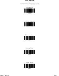
7.5 <strong>Bar</strong> <strong>Code</strong>s<br />
To use these bar codes to configure your Flic scanner, print the appropriate page. Then use your scanner to<br />
read the appropriate bar code.<br />
7.5.1 Device Option Control <strong>Bar</strong> <strong>Code</strong>s<br />
Return to Factory Default Settings Return to NCR Default Settings<br />
4800 Baud* (FWV 1.7.0) 9600 Baud # (FWV 1.7.0)<br />
ACK/NAK Protocol<br />
Enable Disable* #<br />
Auto Download Data<br />
Enable* # Disable<br />
Beep Control<br />
Enable* # Disable<br />
Delay Between <strong>Bar</strong> <strong>Code</strong>s<br />
None* 500ms<br />
1100ms # 1600ms<br />
* Factory Default Setting<br />
# NCR Factory Default Setting<br />
9/29/2003 Page 35
DA0110468 Rev A Flic ® <strong>Laser</strong> <strong>Bar</strong> <strong>Code</strong> <strong>Scanner</strong> Developer’s <strong>Guide</strong><br />
ETX Suffix Character<br />
Enable Disable* #<br />
LED Control<br />
Enable* # Disable<br />
Line Feed Suffix Character<br />
Enable* Disable #<br />
STX Prefix Character<br />
Enable* Disable #<br />
* Factory Default Setting<br />
# NCR Factory Default Setting<br />
9/29/2003 Page 36
DA0110468 Rev A Flic ® <strong>Laser</strong> <strong>Bar</strong> <strong>Code</strong> <strong>Scanner</strong> Developer’s <strong>Guide</strong><br />
7.5.2 Symbology Selection Control <strong>Bar</strong> <strong>Code</strong>s<br />
Enable All Symbologies<br />
<strong>Code</strong> 39<br />
Enable* # Disable<br />
<strong>Code</strong> 128<br />
Enable* # Disable<br />
EAN-8<br />
Enable* # Disable<br />
UPC-A/EAN-13<br />
Enable* # Disable<br />
UPC-E<br />
Enable* # Disable<br />
* Factory Default Setting<br />
# NCR Factory Default Setting<br />
9/29/2003 Page 37
DA0110468 Rev A Flic ® <strong>Laser</strong> <strong>Bar</strong> <strong>Code</strong> <strong>Scanner</strong> Developer’s <strong>Guide</strong><br />
7.5.3 Supplemental <strong>Bar</strong> <strong>Code</strong>s<br />
Auto-Detect Supplemental <strong>Code</strong>s*<br />
Require Supplemental codes Disable Supplemental <strong>Code</strong>s #<br />
AIM Symbol Identifiers<br />
Enable Disable* #<br />
Combine <strong>Bar</strong> <strong>Code</strong>s (FWV 1.7.0)<br />
Enable Disable*<br />
NCR Symbol Identifiers<br />
Enable # Disable*<br />
* Factory Default Setting<br />
# NCR Factory Default Setting<br />
9/29/2003 Page 38
DA0110468 Rev A Flic ® <strong>Laser</strong> <strong>Bar</strong> <strong>Code</strong> <strong>Scanner</strong> Developer’s <strong>Guide</strong><br />
7.5.4 Symbology Options Control <strong>Bar</strong> <strong>Code</strong>s<br />
<strong>Code</strong> 39 Options<br />
<strong>Code</strong>39 Checksum Enable <strong>Code</strong>39 Checksum Disable* #<br />
<strong>Code</strong>39 Stripped Checksum Enable<br />
(Disables both <strong>Code</strong> 39 Checksum options)<br />
UPC/EAN Options<br />
Convert UPC-A codes to EAN-13 codes (FWV 1.8.0) Do Not Convert UPC-A codes* # (FWV 1.8.0)<br />
Expand UPC-E codes to UPC-A codes Do Not Expand UPC-E codes* #<br />
Standard Scanning* # (FWV 1.8.0) Aggressive Scanning (FWV 1.8.0)<br />
7.5.5 Command Control <strong>Bar</strong> <strong>Code</strong>s<br />
Clear Device <strong>Bar</strong> <strong>Code</strong> Memory<br />
* Factory Default Setting<br />
# NCR Factory Default Setting<br />
9/29/2003 Page 39
DA0110468 Rev A Flic ® <strong>Laser</strong> <strong>Bar</strong> <strong>Code</strong> <strong>Scanner</strong> Developer’s <strong>Guide</strong><br />
7.6 ASCII Chart<br />
Use this ASCII chart to convert characters to hexadecimal, and hexadecimal values to characters. For<br />
example, the ampersand (&) is represented as 0x26, or as & in ASCII.<br />
The hexadecimal values can appear in the bar code data. Additionally, you can use the hexadecimal number<br />
to write a name to the User ID field.<br />
Note: Non-printable characters are provided for reference in the first and second rows, and in the 7F<br />
character.<br />
0 1 2 3 4 5 6 7 8 9 A B C D E F<br />
0 NUL SOH STX ETX EOT ENQ ACK BEL BS HT LF VT FF CR SO SI<br />
1 DLE DC1 DC2 DC3 DC4 NAK SYN ETB CAN EM SUB ESC FS GS RS US<br />
2 SP ! " # $ % & ' ( ) * + , - . /<br />
3 0 1 2 3 4 5 6 7 8 9 : ; < = > ?<br />
4 @ A B C D E F G H I J K L M N O<br />
5 P Q R S T U V W X Y Z [ \ ] ^ _<br />
6 ` a b c d e f g h i j k l m n o<br />
7 p q r s t u v w x y z { | } ~ DEL<br />
9/29/2003 Page 40