MS9500 Voyager Series - Metrologic-Shop.de
MS9500 Voyager Series - Metrologic-Shop.de
MS9500 Voyager Series - Metrologic-Shop.de

You also want an ePaper? Increase the reach of your titles
YUMPU automatically turns print PDFs into web optimized ePapers that Google loves.
METROLOGIC INSTRUMENTS, INC.<br />
<strong>MS9500</strong> <strong>Voyager</strong> ® <strong>Series</strong><br />
Single-Line Hand-Held Laser Scanner<br />
Installation and User’s Gui<strong>de</strong>
LOCATIONS<br />
CORPORATE HEADQUARTERS<br />
NORTH AMERICA<br />
ii<br />
EUROPEAN, MIDDLE EAST & AFRICAN<br />
HEADQUARTERS<br />
USA, NEW JERSEY GERMANY, MUNICH<br />
<strong>Metrologic</strong> Instruments, Inc. <strong>Metrologic</strong> Instruments GmbH<br />
Tel: 1-800-ID-METRO Fax: 856-228-6673 Tel: 49-89-89019-0 Fax: 49-89-89019-200<br />
Email: info@metrologic.com Email: info@europe.metrologic.com<br />
SOUTH AMERICA, BRAZIL SÃO PAULO GERMANY, MUNICH<br />
<strong>Metrologic</strong> do Brasil Ltda. <strong>Metrologic</strong> Instruments GmbH<br />
Tel: 55-11-5182-8226 Fax: 55-11-5182-8315 Tel: 49-89-89019-0 Fax: 49-89-89019-200<br />
Email: info@br.metrologic.com Email: info@<strong>de</strong>.metrologic.com<br />
SOUTH AMERICA, OUTSIDE BRAZIL SÃO PAULO ITALY, BOLOGNA<br />
<strong>Metrologic</strong> South America <strong>Metrologic</strong> Instruments Italia srl<br />
Tel: 55-11-5182-7273 Fax: 55-11-5182-7198 Tel: +39 0 51 6511978 Fax: +39 0 51 6521337<br />
Email: info@sa.metrologic.com Email: info@it.metrologic.com<br />
ASIA, SINGAPORE FRANCE, PARIS<br />
<strong>Metrologic</strong> Asia (Pte) Ltd <strong>Metrologic</strong> Eria France SA<br />
Tel: 65-6842-7155 Fax: 65-6842-7166 Tel: +33 (0) 1 48.63.78.78<br />
Email: info@sg.metrologic.com Fax: +33 (0) 1 48.63.24.94<br />
Email: info@fr.metrologic.com<br />
CHINA, SUZHOU<br />
Metro Technologies Co., Ltd. SPAIN, MADRID<br />
Tel: 86-512-62572511 Fax: 86-512-62571517 <strong>Metrologic</strong> Eria Ibérica, SL<br />
Email: info@cn.metrologic.com Tel: +34 913 272 400 Fax: +34 913 273 829<br />
Email: info@es.metrologic.com<br />
Metro Sales Office<br />
Tel: 86-512-67622550 Fax: 86-512-67622560 <strong>Metrologic</strong> Europe Repair Center (MERC)<br />
Email: info@cn.metrologic.com <strong>Metrologic</strong> Eria Ibérica, SL<br />
Tel: +34 913 751 249 Fax: +34 913 270 437<br />
JAPAN, TOKYO<br />
<strong>Metrologic</strong> Japan Co., Ltd. UNITED KINGDOM, BASINGSTOKE<br />
Tel: 81-03-3839-8511 Fax: 81-03-3839-8519 <strong>Metrologic</strong> Instruments UK Limited<br />
Email: info@jp.metrologic.com Tel: +44 (0) 1256 365900<br />
Fax: +44 (0) 1256 365955<br />
Email: info@uk.metrologic.com<br />
RUSSIA, MOSCOW<br />
<strong>Metrologic</strong> Russia<br />
Tel: +7 095 730 7424 Fax: +7 095 730 7425<br />
Email: info@ru.metrologic.com<br />
Copyright<br />
© 2003 by <strong>Metrologic</strong> Instruments, Inc. All rights reserved. No part of this work may be reproduced, transmitted, or stored<br />
in any form or by any means without prior written consent, except by reviewer, who may quote brief passages in a review,<br />
or provi<strong>de</strong>d for in the Copyright Act of 1976.<br />
Products and brand names mentioned in this document are tra<strong>de</strong>marks of their respective companies.
TABLE OF CONTENTS<br />
Introduction........................................................................................................... 1<br />
Scanner and Accessories..................................................................................... 2<br />
Operation Test...................................................................................................... 4<br />
Installing the Scanner to the Host System<br />
MS9520-00/9/11/14/41 AND MS9540-00/9/11/14/41......................................... 5<br />
Keyboard Wedge MS9520-47 and MS9540-47................................................ 6<br />
Stand Alone Keyboard ..................................................................................... 7<br />
Integrated USB<br />
Full Speed MS9520-40 and MS9540-40 ...................................................... 8<br />
Low Speed POS MS9520-39 and MS9540-39............................................. 8<br />
Low Speed HID MS9520-38 and MS9540-38 .............................................. 8<br />
Installation Notes for External USB Interface ................................................... 8<br />
The PowerLink Cable<br />
Disconnecting................................................................................................... 9<br />
Connecting ....................................................................................................... 9<br />
The MS9540 <strong>Voyager</strong>CG ® <strong>Series</strong><br />
How to Use Co<strong>de</strong>Gate ® and the Manual Activation Mo<strong>de</strong>.............................. 10<br />
Three Mo<strong>de</strong>s of Operation ............................................................................. 10<br />
Stand Kits<br />
Parts............................................................................................................... 11<br />
Assembly........................................................................................................ 12<br />
Scanner Parts..................................................................................................... 15<br />
Audible Indicators............................................................................................... 16<br />
Visual Indicators ................................................................................................. 17<br />
Failure Mo<strong>de</strong>s..................................................................................................... 18<br />
Programming Mo<strong>de</strong>s .......................................................................................... 19<br />
Upgrading the Flash ROM Firmware.................................................................. 22<br />
Labels................................................................................................................. 23<br />
Maintenance....................................................................................................... 23<br />
Depth of Field..................................................................................................... 24<br />
iii
TABLE OF CONTENTS<br />
IR Activation ....................................................................................................... 25<br />
Applications and Protocols ................................................................................. 26<br />
Troubleshooting Gui<strong>de</strong> ....................................................................................... 27<br />
RS-232 Demonstration Program ........................................................................ 31<br />
Design Specifications<br />
Operational..................................................................................................... 32<br />
Mechanical ..................................................................................................... 32<br />
Electrical......................................................................................................... 33<br />
Environmental ................................................................................................ 33<br />
Default Settings.................................................................................................. 34<br />
Scanner and Cable Terminations<br />
Scanner Pinout Connections.......................................................................... 39<br />
Cable Connector Configurations .................................................................... 41<br />
Limited Warranty ................................................................................................ 43<br />
Notices ............................................................................................................... 44<br />
Patents ............................................................................................................... 45<br />
In<strong>de</strong>x................................................................................................................... 46<br />
iv
INTRODUCTION<br />
The <strong>Voyager</strong> ® <strong>MS9500</strong> <strong>Series</strong> single-line hand-held scanners inclu<strong>de</strong> both the<br />
MS9520 and MS9540.<br />
The <strong>Voyager</strong>CG ® MS9540 features <strong>Metrologic</strong>’s patented Co<strong>de</strong>Gate ®<br />
technology. Co<strong>de</strong>Gate is an intuitive scanning system that is i<strong>de</strong>al for all<br />
scanning applications, including menu-scanning, point-of-sale, document<br />
processing, and inventory control.<br />
Co<strong>de</strong>Gate works hand-in-hand with <strong>Metrologic</strong>’s patented automatic-triggering<br />
scheme. Simply present a bar co<strong>de</strong> to the scanner; the high-visibility<br />
650-nanometer laser is automatically activated allowing the user to easily select<br />
the bar co<strong>de</strong> to be scanned. Press the Co<strong>de</strong>Gate button and the data is<br />
transmitted to the host system.<br />
Equipped with both ‘in-stand’ and ‘out-of-stand’ operation, <strong>Voyager</strong> can be used<br />
as both a hand-held and fixed projection scanner. <strong>Voyager</strong> automatically senses<br />
when it is placed in the stand and <strong>de</strong>-activates the Co<strong>de</strong>Gate button.<br />
If the advantage of Co<strong>de</strong>Gate technology is unnecessary in your application,<br />
then the MS9520 is the <strong>Voyager</strong> of choice. The MS9520 is packed with all of the<br />
same features as the MS9540, with the exception of Co<strong>de</strong>Gate.<br />
<strong>Metrologic</strong> has inclu<strong>de</strong>d many standard features such as: user programmable<br />
Flash ROM, PowerLink user-replaceable cables, MetroSet ® 2 and MetroSelect ®<br />
configuration, EMI rating of Class B, data editing (parsing) capability using<br />
Bits ‘n’ Pieces ® , and a 5-year limited warranty.<br />
VOYAGER VOYAGERCG INTERFACE<br />
MS9520 – 00 MS9540 – 00 Laser Emulation RS-232 Transmit/Receive<br />
MS9520 – 9 MS9540 – 9 OCIA<br />
MS9520 – 11 MS9540 – 11 IBM 468X/469X, RS232-TXD, RXD, RTS, CTS<br />
MS9520 – 14 MS9540 – 14 RS232 - TXD, RXD, RTS, CTS, DTR, DSR<br />
MS9520 – 38 MS9540 – 38 Low Speed USB, HID<br />
MS9520 – 39 MS9540 – 39 Low Speed USB, POS<br />
MS9520 – 40 MS9540 – 40 Full Speed USB<br />
MS9520 – 41 MS9540 – 41 RS-232/Light Pen Emulation<br />
MS9520 – 47 MS9540 – 47<br />
Keyboard Wedge, Stand-Alone Keyboard and<br />
RS232 Transmit/Receive<br />
1
SCANNER AND ACCESSORIES<br />
2<br />
BASIC KIT<br />
Part # Description<br />
<strong>MS9500</strong> <strong>Voyager</strong> <strong>Series</strong> Scanner<br />
00-02544 MetroSelect Single-Line Programming Gui<strong>de</strong>*<br />
00-02410<br />
<strong>MS9500</strong> <strong>Voyager</strong> <strong>Series</strong> Single-Line Hand Held Laser<br />
Scanner Installation and User’s Gui<strong>de</strong><br />
* Available on the <strong>Metrologic</strong> website - www.metrologic.com<br />
OPTIONAL ACCESSORIES<br />
Part # Description<br />
AC to DC Power Transformer- Regulated 5.2VDC @ 650 mA output.<br />
45-45593 120V United States<br />
45-45591 220V-240V Continental European<br />
45-45592 220V-240V United Kingdom<br />
46-46803 220V-240V Australia<br />
46-46931 220V-240V China<br />
54-54xxx<br />
53-53xxx<br />
PowerLink Cable with built in power jack<br />
2.1m (7') straight cord, short strain relief<br />
PowerLink Cable with built in power jack<br />
2.7m (9') coiled cord, long strain relief<br />
xxx specifies connection to the host<br />
53-53002 Keyboard Wedge PowerLink Cable with Adapter Cable<br />
53-53020 Stand Alone Keyboard Wedge PowerLink Cable<br />
Other items may be or<strong>de</strong>red for the specific protocol being used. To or<strong>de</strong>r additional items,<br />
contact the <strong>de</strong>aler, distributor or call <strong>Metrologic</strong>’s Customer Service Department at<br />
1-800-ID-METRO or 1-800-436-3876.
SCANNER AND ACCESSORIES<br />
OPTIONAL ACCESSORIES<br />
Part # Description<br />
53-53213<br />
53-53214<br />
USB Power/Communication Cable,<br />
3 m (10’) coiled cord, long strain relief, gray<br />
USB Power/Communication Cable,<br />
5 m (10’) coiled cord, long strain relief, gray<br />
Not for use with Low Speed USB scanners.<br />
Use with Full Speed USB scanners only.<br />
MX009-2** MX009 USB Converter Cable<br />
MVC**<br />
<strong>Metrologic</strong> Voltage Converter Cable<br />
+12VDC to +5.2VDC or -12VDC to +5.2VDC<br />
** Contact a <strong>Metrologic</strong> customer service representative for additional<br />
information on the MVC and MX009 converter cable series and the host<br />
connections available.<br />
46-46128 Free-Standing Stand with Accessories<br />
46-46351 Hard Mount Accessory Kit (used with kit #46-46128)<br />
46-46433 OR<br />
46-46508<br />
Wall Mount Hanger Accessory Kit<br />
Other items may be or<strong>de</strong>red for the specific protocol being used. To or<strong>de</strong>r additional items,<br />
contact the <strong>de</strong>aler, distributor or call <strong>Metrologic</strong>’s Customer Service Department at<br />
1-800-ID-METRO or 1-800-436-3876.<br />
3
OPERATIONAL TEST<br />
1. Connect the 10-pin RJ45 male<br />
connector into the jack on the<br />
<strong>Voyager</strong> or <strong>Voyager</strong>CG. You<br />
will hear a ‘click’ when the<br />
connection is ma<strong>de</strong>.<br />
2. Connect the L-shaped plug<br />
of the power supply into the<br />
power jack on the PowerLink<br />
cable.<br />
3. Connect the power supply into<br />
an AC outlet. Make sure the<br />
AC input requirements of the<br />
power supply match the AC<br />
outlet.<br />
4. When the <strong>Voyager</strong> is ready to<br />
scan, the green LED will turn<br />
on, the red LED will flash and<br />
the scanner will beep once.<br />
5. Place a bar co<strong>de</strong> in front of<br />
the scanning window. The<br />
scanner will beep once and<br />
flash the red LED if the bar<br />
co<strong>de</strong> was successfully<br />
<strong>de</strong>co<strong>de</strong>d and transmitted<br />
(<strong>de</strong>fault mo<strong>de</strong> only). For the<br />
MS9540, press the Co<strong>de</strong>Gate<br />
button to transmit the data.<br />
4<br />
Figure 2.<br />
Figure 1.<br />
Figure 3.<br />
All <strong>Voyager</strong>’s are shipped configured with a set of factory <strong>de</strong>faults. Refer to<br />
the MetroSelect Configuration Gui<strong>de</strong> or MetroSet ® 2’s help files for<br />
instructions on how to configure the scanner.<br />
Caution:<br />
To maintain compliance with applicable standards, all circuits connected to the scanner must<br />
meet the requirements for SELV (Safety Extra Low Voltage) according to EN 60950.<br />
To maintain compliance with standard CSA C22.2 No. 950/UL 1950 and norm EN 60950, the<br />
power source should meet applicable performance requirements for a limited power source.
INSTALLING THE SCANNER TO THE HOST SYSTEM<br />
MS9520-00/9/11/14/41 AND MS9540-00/9/11/14/41<br />
1. Turn off the host system.<br />
2. Connect the 10-pin RJ45 male<br />
connector into the jack on the<br />
<strong>Voyager</strong> or <strong>Voyager</strong>CG. You will<br />
hear a ‘click’ when the connection<br />
is ma<strong>de</strong>.<br />
If the scanner is receiving<br />
power from the host system,<br />
skip to step #5.<br />
3. Connect the L-shaped plug of the<br />
power supply into the power jack<br />
on the PowerLink cable.<br />
4. Make sure the AC input<br />
requirements of the power supply<br />
match the AC outlet. Connect the<br />
power supply into an AC outlet. The<br />
outlet should be near the equipment<br />
and easily accessible.<br />
5. Connect the PowerLink cable to the<br />
proper port on the host system.<br />
6. Turn on the host system.<br />
Plugging the scanner into a port on the host system does not<br />
guarantee that scanned information will be communicated properly to<br />
the host system. All <strong>Voyager</strong>’s are shipped configured with a set of<br />
factory <strong>de</strong>faults. Please refer to the MetroSelect Programming Gui<strong>de</strong><br />
or MetroSet2’s help files for instructions on changing the scanner’s<br />
configuration. It is important to check that the scanner and host system<br />
are using the same communication protocol.<br />
All MS9520-00/MS9540-00 scanners leave the factory with the Laser<br />
Emulation Mo<strong>de</strong> enabled. If you recall <strong>de</strong>faults while re-configuring<br />
your scanner the Laser Emulation Mo<strong>de</strong> will no longer be enabled.<br />
Refer to the MS9520/9540-00 Laser Emulation Mo<strong>de</strong> section of the<br />
MetroSelect Single-Line Configuration Gui<strong>de</strong> for information on<br />
enabling the Laser Emulation Mo<strong>de</strong>.<br />
Caution:<br />
Figure 4.<br />
To maintain compliance with applicable standards, all circuits connected to the scanner must<br />
meet the requirements for SELV (Safety Extra Low Voltage) according to EN 60950.<br />
To maintain compliance with standard CSA C22.2 No. 950/UL 1950 and norm EN 60950, the<br />
power source should meet applicable performance requirements for a limited power source.<br />
5
INSTALLING THE SCANNER TO THE HOST SYSTEM<br />
KEYBOARD WEDGE MS9520-47 AND MS9540-47<br />
1. Turn off the PC.<br />
2. Connect the 10-pin RJ45 male<br />
connector into the jack on the<br />
<strong>Voyager</strong> or the <strong>Voyager</strong>CG. You<br />
will hear a ‘click’ when the<br />
connection is ma<strong>de</strong>.<br />
3. Connect the L-shaped plug of the<br />
power supply into the power jack<br />
on the PowerLink cable.<br />
6<br />
If the scanner is receiving<br />
power from the host system,<br />
skip to step #5.<br />
4. Make sure the AC input<br />
requirements of the power supply<br />
match the AC outlet. Connect the<br />
power supply into an AC outlet.<br />
The outlet should be near the<br />
equipment and easily accessible.<br />
5. Disconnect the keyboard from the<br />
PC.<br />
6. Connect the PowerLink cable to the<br />
keyboard and the PC’s keyboard port.<br />
If necessary use the supplied adapter<br />
cable (5-pin male DIN to 6-pin female<br />
mini DIN adapter).<br />
7. Power up the PC.<br />
Figure 5.<br />
Powering the MS9520-47/MS9540-47 directly from the computer can<br />
sometimes cause interference with the operation of the scanner or the<br />
computer. Not all computers supply the same current through the<br />
keyboard port, explaining why a scanner may work on one computer<br />
and not another. Contact a <strong>Metrologic</strong> Customer Service<br />
Representative if you require an external power supply.<br />
Caution:<br />
To maintain compliance with applicable standards, all circuits connected to the scanner must<br />
meet the requirements for SELV (Safety Extra Low Voltage) according to EN 60950.<br />
To maintain compliance with standard CSA C22.2 No. 950/UL 1950 and norm EN 60950, the<br />
power source should meet applicable performance requirements for a limited power source.
INSTALLING THE SCANNER TO THE HOST SYSTEM<br />
STAND ALONE KEYBOARD<br />
1. Turn off the host system.<br />
2. Connect the 10-pin RJ45 male<br />
connector into the jack on the<br />
<strong>Voyager</strong> or <strong>Voyager</strong>CG. You will<br />
hear a ‘click’ when the connection is<br />
ma<strong>de</strong>.<br />
If the scanner is receiving<br />
power from the host system,<br />
skip to step #5.<br />
3. Connect the L-shaped plug of the<br />
power supply into the power jack on<br />
the PowerLink cable.<br />
4. Make sure the AC input<br />
requirements of the power supply<br />
match the AC outlet. Connect the<br />
power supply into an AC outlet.<br />
The outlet should be near the<br />
equipment and easily accessible.<br />
5. Connect the PowerLink cable to the<br />
keyboard port on the host system.<br />
6. Turn on the host system.<br />
Figure 6.<br />
Powering the MS9520-47/MS9540-47 directly from the computer can<br />
sometimes cause interference with the operation of the scanner or the<br />
computer. Not all computers supply the same current through the<br />
keyboard port, explaining why a scanner would work on one computer and<br />
not another. Contact a <strong>Metrologic</strong> Customer Service Representative if you<br />
require an external power supply.<br />
Caution:<br />
To maintain compliance with applicable standards, all circuits connected to the scanner must<br />
meet the requirements for SELV (Safety Extra Low Voltage) according to EN 60950.<br />
To maintain compliance with standard CSA C22.2 No. 950/UL 1950 and norm EN 60950, the<br />
power source should meet applicable performance requirements for a limited power source.<br />
7
INSTALLING THE SCANNER TO THE HOST SYSTEM<br />
INTEGRATED USB: FULL SPEED MS9520-40 AND MS9540-40<br />
LOW SPEED POS MS9520-39 AND MS9540-39<br />
LOW SPEED HID MS9520-38 AND MS9540-38<br />
1. Turn off the host system.<br />
2. Connect the 10-pin RJ45 male<br />
connector of the USB cable into the<br />
jack on the <strong>Voyager</strong> or <strong>Voyager</strong>CG.<br />
You will hear a ‘click’ when the<br />
connection is ma<strong>de</strong>.<br />
3. Connect the other end of the USB<br />
cable to the host USB port.<br />
4. Turn on the host system.<br />
8<br />
Plugging the scanner into a port on the host<br />
system does not guarantee that scanned<br />
information will be communicated properly to<br />
the host system. All <strong>Voyager</strong>’s are shipped<br />
already configured with a set of factory<br />
<strong>de</strong>faults. Please refer to the MetroSelect<br />
Programming Gui<strong>de</strong> or MetroSet2’s help files<br />
for instructions on changing the scanner’s<br />
configuration. It is important to check that<br />
the scanner and host system are using the<br />
same communication protocol.<br />
Figure 7.<br />
Caution:<br />
To maintain compliance with applicable standards, all circuits connected to the scanner must<br />
meet the requirements for SELV (Safety Extra Low Voltage) according to EN 60950.<br />
To maintain compliance with standard CSA C22.2 No. 950/UL 1950 and norm EN 60950, the<br />
power source should meet applicable performance requirements for a limited power source.<br />
INSTALLATION NOTES FOR EXTERNAL USB INTERFACE<br />
<strong>Metrologic</strong>’s MX009 USB cable is a <strong>de</strong>vice that converts serial RS232 formatted<br />
data to either USB Keyboard or USB Point-of Sale communication protocol.<br />
Please refer to the MX009 USB Converter Cable Programming Gui<strong>de</strong><br />
(MLPN 00-02574) supplied with your MX009 cable for <strong>de</strong>tailed installation and<br />
programming gui<strong>de</strong>lines.
THE POWERLINK CABLE<br />
DISCONNECTING THE POWERLINK CABLE<br />
Before removing the cable from the scanner, <strong>Metrologic</strong> recommends that the<br />
power on the host system is off and the power supply has been disconnected<br />
from the PowerLink cable.<br />
Figure 8.<br />
1. Locate the small ‘pin-hole’ on the top of the unit near the bottom of the<br />
<strong>Voyager</strong> logo.<br />
2. Bend an ordinary paperclip into the shape shown above.<br />
3. Insert the paperclip (or other small metallic pin) into the small ‘pin-hole’.<br />
4. You will here a faint ‘click’. Pull gently on the strain-relief of the PowerLink<br />
cable and it will sli<strong>de</strong> out of the scanner.<br />
CONNECTING THE POWERLINK CABLE<br />
Important: If the PowerLink cable is not fully latched the unit can power<br />
intermittently.<br />
Figure 9a. Figure 9b.<br />
9
THE MS9540 VOYAGERCG ® SERIES<br />
HOW TO USE CODEGATE AND THE MANUAL ACTIVATION MODE<br />
10<br />
CODEGATE ®<br />
MANUAL ACTIVATION MODE*<br />
* This feature is not a <strong>de</strong>fault setting.<br />
Refer to the MetroSelect Configuration<br />
Gui<strong>de</strong> for instructions on enabling the<br />
Manual Activation Mo<strong>de</strong>.<br />
Figure 10a. Figure 10b.<br />
THREE MODES OF OPERATION<br />
Auto Trigger, In-Stand<br />
• Auto-triggers while in the stand<br />
• Bar co<strong>de</strong> is automatically <strong>de</strong>co<strong>de</strong>d and transmitted<br />
Co<strong>de</strong>Gate, Out-of-Stand<br />
• Co<strong>de</strong>Gate activates when removed from the stand<br />
• Bar co<strong>de</strong> data is transmitted when the button is pressed<br />
Manual Activation Mo<strong>de</strong>*, Out-of-Stand<br />
• Button activates laser<br />
• Bar co<strong>de</strong> data is scanned and transmitted while button is held down
STAND KITS<br />
Free Standing Kits #46-46128<br />
Contains:<br />
a. Stand (MLPN 36-00454)................................Qty 1<br />
b. Apron (MLPN 50-50440) ...............................Qty 1<br />
c. Screw, M3 x 6 mm (MLPN 18-18670)............Qty 2<br />
d. Washer, #5 x .5 OD (MLPN 18-18671)..........Qty 2<br />
e. Stand Anchor (MLPN 50-50449) ...................Qty 1<br />
f. M3 x 20 mm Set Screw (MLPN 18-18672).....Qty 1<br />
Optional Hard Mount Accessory Kit #46-46351<br />
This kit, used in conjunction with the stand kit<br />
(#46-46128), can be used to hard mount (bolt)<br />
the <strong>MS9500</strong> to the countertop.<br />
Contains:<br />
a. Screw, #8 Round Head (MLPN 18-18057) ....Qty 4<br />
b. Base (MLPN 36-36080).................................Qty 1<br />
Optional Wall Mount Hanger Accessory<br />
Kit #46-46433<br />
Contains:<br />
a. Screw #8 Round Head (MLPN 18-18057) .....Qty.2<br />
b. Wall Mount Hanger (MLPN 18-18057)...........Qty.1<br />
Optional Wall Mount Hanger Kit #46-46508<br />
Contains:<br />
a. Wall Mount Hanger ( MLPN 36-00611 )........Qty. 1<br />
b. Wall Mount Base (MLPN 36-00812) ...........Qty. 1<br />
c. 4.8 x 13 mm, Self Tapping Screw .............Qty. 2<br />
(MLPN 18-18233)<br />
d. Double-Si<strong>de</strong>d Adhesive Tape .....................Qty. 1<br />
(MLPN 36-00821)<br />
e. #8 Wood Screw (MLPN 18-18057) ..............Qty. 2<br />
a.<br />
b.<br />
b.<br />
Figure 13.<br />
a.<br />
Figure 14.<br />
Figure 15.<br />
Figure 16.<br />
e.<br />
f.<br />
d.<br />
c.<br />
11
ASSEMBLING THE STAND<br />
There are two options for assembling the stand. The first option is a selfsupporting<br />
stand that can be moved freely about on the countertop. The second<br />
option is used if the stand will be bolted or hard-mounted to the countertop.<br />
Stand Option 1: Self-Supported Stand Kit #46-46128<br />
Step 1<br />
Sli<strong>de</strong> the apron (MLPN 50-50440)<br />
over the stand (MLPN 36-00454).<br />
Step 2<br />
Position the stand so that it sits<br />
un<strong>de</strong>r the tab on the apron.<br />
Then secure the apron to the<br />
stand using the two M3 x 6 mm<br />
screws (MLPN 18-18670) and the<br />
two #5 washers (MLPN 18-18671)<br />
provi<strong>de</strong>d.<br />
Stand Option 2: Hard-Mount Accessory Kit #46-46351<br />
2.00 in<br />
#8 Wood<br />
Screw<br />
12<br />
2.00 in<br />
Figure 19.<br />
Figure 20.<br />
Base<br />
Step 1<br />
Figure 17.<br />
Figure 18.<br />
Drill four #39 holes in the countertop.<br />
Step 2<br />
Apron<br />
Tab<br />
M3 x 6 mm<br />
Screw<br />
Apron<br />
Stand<br />
Stand<br />
Secure the base (MLPN 36-36080)<br />
to the countertop with the four #8 wood<br />
screws (MLPN 18-18057) provi<strong>de</strong>d.<br />
#5 Washer
ASSEMBLING THE STAND<br />
Stand Option 2: Hard-Mount Kits #46-46128, #46-46351 and<br />
MS951 Stand Replacements<br />
Anchor from<br />
Kit #46-46128<br />
Base Assembly from<br />
Kit #46-46351 or<br />
MS951 Stand Base<br />
Figure 21.<br />
Figure 22.<br />
Figure 23.<br />
Figure 24.<br />
Figure 25.<br />
Step 3<br />
Screw the stand anchor (MLPN 50-50449)<br />
onto the base assembly until it sits flush.<br />
Step 4<br />
Remove the logo plate on the stand by<br />
gently using an exacto knife to release<br />
the plate hook.<br />
Step 5<br />
Position the stand over the base<br />
assembly.<br />
Step 6<br />
Secure the stand to the base assembly<br />
by installing and tightening the M3 set<br />
screw (MLPN 18-18672) un<strong>de</strong>r the logo<br />
plate as shown.<br />
Step 7<br />
Snap the logo plate back into place.<br />
13
ASSEMBLING THE STAND<br />
Wall Mount, Option 1:<br />
For Kit #46-46433 or #46-46508<br />
14<br />
Step 1<br />
Drill two #39 pilot holes 3.00” apart.<br />
Step 2<br />
Attach the Wall Mount Hanger to the wall<br />
with the two #8 wood screws provi<strong>de</strong>d.<br />
Wall Mount, Option 2:<br />
Kit #46-46508<br />
Step 1<br />
Attach the Wall Mount Base to the Wall<br />
Mount Hanger with the two 4.8 x 13 mm<br />
self-tapping screws.<br />
Step 2<br />
Remove one si<strong>de</strong> of the protective<br />
backing from the double-si<strong>de</strong>d adhesive<br />
tape.<br />
Step 3<br />
Attach the tape to the back of the Wall<br />
Mount Hanger as shown.<br />
Step 4<br />
Remove the protective backing from the<br />
double-si<strong>de</strong>d adhesive tape and apply<br />
hook to the wall.<br />
Figure 26.<br />
Figure 27.<br />
Figure 28.
SCANNER PARTS<br />
Red LED<br />
Green LED<br />
Output Window<br />
Yellow LED*<br />
Co<strong>de</strong>Gate Button*<br />
<strong>MS9500</strong> Top View<br />
Cable Connection<br />
<strong>MS9500</strong> Si<strong>de</strong> View<br />
* This feature is not available on the MS9520<br />
Figure 29.<br />
15
AUDIBLE INDICATORS<br />
When the <strong>Voyager</strong> is in operation, it provi<strong>de</strong>s audible feedback. These sounds<br />
indicate the status of the scanner. Eight settings are available for the tone of the<br />
beep (normal, 6 alternate tones and no tone). To change the beeper tone, refer<br />
to the MetroSelect Single-Line Programming Gui<strong>de</strong> or MetroSet2’s help files.<br />
16<br />
One Beep<br />
When the scanner first receives power, the green LED will<br />
turn on, then the red LED will flash and the scanner will<br />
beep once. The red LED will remain on for the duration of<br />
the beep. The scanner is ready to scan.<br />
When the scanner successfully reads a bar co<strong>de</strong>, the red<br />
LED will flash and the scanner beeps once (if programmed<br />
to do so). If the scanner does not beep once and the green<br />
light does not flash, then the bar co<strong>de</strong> has not been<br />
successfully read.<br />
Razzberry Tone<br />
This tone is a failure indicator. Refer to “Failure<br />
Mo<strong>de</strong>s" page 18.<br />
Two Beeps – On Power Up<br />
When a Flash ROM upgra<strong>de</strong> is nee<strong>de</strong>d, the scanner will<br />
beep twice followed by alternating flashes of the green and<br />
red LEDs.<br />
Three Beeps - During Operation<br />
When entering configuration mo<strong>de</strong>, the red LED will flash<br />
while the scanner simultaneously beeps three times. The<br />
red and green LEDs will continue to flash while in this<br />
mo<strong>de</strong>. Upon exiting configuration mo<strong>de</strong>, the scanner will<br />
beep three times, and the LEDs will stop flashing.<br />
When configured, 3 beeps can also indicate a<br />
communications timeout during normal scanning mo<strong>de</strong>.<br />
When using one-co<strong>de</strong>-programming, the scanner will beep<br />
three times (the current selected tone), followed by a short<br />
pause then by a high tone and a low tone. This tells the<br />
user that the single configuration bar co<strong>de</strong> has successfully<br />
configured the scanner.<br />
Three Beeps - On Power Up<br />
This is a failure indicator. Refer to “Failure Mo<strong>de</strong>s” on<br />
page 18.
VISUAL INDICATORS<br />
The MS9540 has three LED indicators (green, red and yellow) located on the<br />
head of the scanner. The MS9520 has two LED indicators (green and red)<br />
located on the head of the scanner. When the scanner is on, the flashing or<br />
stationary activity of the LEDs indicates the status of the current scan and the<br />
scanner.<br />
Green, Red & Yellow (MS9540’s Only) LEDs are off<br />
The LEDs will not be illuminated if the scanner is not<br />
receiving power from the host or transformer.<br />
The scanner is in stand-by mo<strong>de</strong>, and Co<strong>de</strong>Gate is<br />
enabled. Present a bar co<strong>de</strong> to the scanner and the<br />
green LED will turn on when the laser turns on.<br />
Steady Yellow (MS9540’s Only)<br />
The Co<strong>de</strong>Gate button is not active. If a bar co<strong>de</strong> is in the<br />
scan field, the laser will turn on. The bar co<strong>de</strong> will be<br />
<strong>de</strong>co<strong>de</strong>d and transmitted to the host automatically.<br />
Steady Green<br />
When the laser is active, the green LED is illuminated.<br />
The green LED will remain illuminated until the laser is<br />
<strong>de</strong>activated (<strong>de</strong>fault mo<strong>de</strong> only).<br />
Steady Green and Single Red Flash<br />
When the scanner successfully reads a bar co<strong>de</strong>, the red<br />
LED will flash and the scanner will beep once. If the red LED<br />
does not flash or the scanner does not beep once, then the<br />
bar co<strong>de</strong> has not been successfully read (<strong>de</strong>fault mo<strong>de</strong> only).<br />
Steady Green and Steady Red<br />
After a successful scan, the scanner transmits the data to<br />
the host <strong>de</strong>vice. Some communication mo<strong>de</strong>s require that<br />
the host inform the scanner when data is ready to be<br />
received. If the host is not ready to accept the information,<br />
the scanner’s red LED will remain on until the data can be<br />
transmitted.<br />
Alternating Flashing of Green and Red<br />
This indicates the scanner is program mo<strong>de</strong>. A razzberry<br />
tone indicates that an invalid bar co<strong>de</strong> has been scanned<br />
while in this mo<strong>de</strong>.<br />
The scanner needs a Flash ROM upgra<strong>de</strong> if the red and<br />
green LEDs flash alternately and the unit beeps three times<br />
during startup.<br />
Steady Red, Green off<br />
This indicates the scanner may be waiting for<br />
communication from the host.<br />
17
FAILURE MODES<br />
18<br />
Flashing Green and one Razzberry Tone<br />
This indicates the scanner has experienced a laser subsystem<br />
failure. Return the unit for repair to an authorized<br />
service center.<br />
Flashing Red and Green with Two Razzberry Tones<br />
This indicates the scanner has experienced a scanning<br />
mechanism failure. Return the unit for repair to an<br />
authorized service center.<br />
Continuous Razzberry Tone with all LEDs off<br />
If, upon power, the scanner emits a continuous razzberry<br />
tone, then the scanner has an experienced an electronic<br />
failure. Return the unit for repair to an authorized service<br />
center.<br />
Three Beeps – on power up<br />
If the scanner beeps 3 times on power up then the nonvolatile<br />
memory (NovRAM) that holds the scanner<br />
configuration has failed. If the scanner does not respond<br />
after reprogramming, return the scanner for repair to an<br />
authorized service center.
PROGRAMMING MODES<br />
The <strong>MS9500</strong> <strong>Voyager</strong> has 3 mo<strong>de</strong>s of programming.<br />
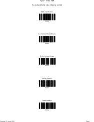
� Bar Co<strong>de</strong>s<br />
<strong>Voyager</strong> or <strong>Voyager</strong> CG can be configured by scanning the bar co<strong>de</strong>s<br />
located in the MetroSelect ® Single-Line Programming Gui<strong>de</strong> (MLPN 00-<br />
02544). Please refer to this gui<strong>de</strong> for instructions. This manual can be<br />
downloa<strong>de</strong>d for FREE from <strong>Metrologic</strong>’s website (www.metrologic.com).<br />
� MetroSet ® 2<br />
This user-friendly Windows-based configuration program allows you to<br />
simply ‘point-and-click’ at the <strong>de</strong>sired scanner options. This program can be<br />
downloa<strong>de</strong>d for FREE from <strong>Metrologic</strong>’ website (www.metrologic.com), or<br />
set-up disks can be or<strong>de</strong>red by calling 1-800-ID-METRO.<br />
� Serial Programming<br />
This mo<strong>de</strong> of programming is i<strong>de</strong>al for OEM applications. This mo<strong>de</strong> gives<br />
the end-user the ability to send a series of commands using the serial port of<br />
the host system. The commands are equivalent to the numerical values of<br />
the bar co<strong>de</strong>s located in the MetroSelect Single-Line Programming Gui<strong>de</strong><br />
(MLPN 00-02544).<br />
How does Serial Programming work?<br />
1. Each command sent to the scanner is the ASCII representation of each<br />
numeral in the configuration bar co<strong>de</strong>. The entire numeric string is framed<br />
with an ASCII [stx] and an ASCII [etx].<br />
EXAMPLE #1:<br />
Command for Disabling Codabar<br />
Command = [stx]100104[etx]<br />
String Sent to Scanner = 02h 31h 30h 30h 31h 30h 34h 03h<br />
(All values are hexa<strong>de</strong>cimal).<br />
2. If the command sent to the scanner is valid, the scanner will respond with an<br />
[ack].<br />
3. If the command sent to the scanner in invalid, the scanner will respond with<br />
a [nak].<br />
NOTE: If this occurs, the end-user must start over at the very beginning of<br />
the configuration sequence. Re-transmitting the invalid command<br />
will not work, the user must start over.<br />
19
PROGRAMMING MODES<br />
4. During programming, the motor and laser turn off. YOU CANNOT SCAN A<br />
BAR CODE WHILE IN SERIAL PROGRAM MODE.<br />
5. There is a 20 second window between commands. If a 20 second timeout<br />
occurs, the scanner will send a [nak] and you must start over.<br />
6. To enter serial program mo<strong>de</strong>, send the following command<br />
[stx]999999[etx].<br />
7. To exit serial program mo<strong>de</strong>, send the following command [stx]999999[etx],<br />
the scanner will respond with an [ack] followed by 3 beeps.<br />
8. This mo<strong>de</strong> uses the current Baud Rate, Parity, Stop Bits and Data Bits<br />
settings that are configured in the scanner. The <strong>de</strong>fault settings of the<br />
scanner are 9600, Space, 2, 7 respectively. If a command is sent to the<br />
scanner to change any of these settings, the change will NOT take effect<br />
until after serial program mo<strong>de</strong> is exited.<br />
20<br />
EXAMPLE #2:<br />
The following example will set the scanner to the factory <strong>de</strong>fault settings,<br />
Disable Scanning of Co<strong>de</strong> 128 bar co<strong>de</strong>s, change the beeper tone, and add<br />
a “G” as a programmable prefix.<br />
HOST SCANNER<br />
FEATURE COMMAND ASCII REPRESENTATION RESPONSE<br />
Enter Program Mo<strong>de</strong> [stx]999999[etx] 02h 39h 39h 39h 39h 39h 39h 03h [ack] or 06h<br />
Load Defaults [stx]999998[etx] 02h 39h 39h 39h 39h 39h 38h 03h [ack] or 06h<br />
Disable Co<strong>de</strong> 128 [stx]100113[etx] 02h 31h 30h 30h 31h 31h 33h 03h [ack] or 06h<br />
Alternate Tone 1 [stx]318565[etx] 02h 33h 31h 38h 35h 36h 35h 03h [ack] or 06h<br />
Prog. Prefix #1 [stx]903500[etx] 02h 39h 30h 33h 35h 30h 30h 03h [ack] or 06h<br />
Co<strong>de</strong> Byte 0 [stx]0[etx] 02h 30h 03h [ack] or 06h<br />
Co<strong>de</strong> Byte 7 [stx]7[etx] 02h 37h 03h [ack] or 06h<br />
Co<strong>de</strong> Byte 1 [stx]1[etx] 02h 31h 03h [ack] or 06h<br />
Exit Program Mo<strong>de</strong> [stx]999999[etx] 02h 39h 39h 39h 39h 39h 39h 03h [ack] or 06h<br />
The scanner will beep three times!<br />
The commands sent to the scanner do not inclu<strong>de</strong> the small superscripted<br />
‘3’ that you see in front of each bar co<strong>de</strong> string in the MetroSelect manual.<br />
THE ‘3’ SHOULD NOT BE SENT. IT IS A CODE TYPE DESIGNATION<br />
ONLY!<br />
As you will note for commands requiring additional bar co<strong>de</strong>s to be scanned<br />
(such as prefixes, suffixes, timeouts, etc.), simply send the co<strong>de</strong> bytes in the<br />
same or<strong>de</strong>r that you would normally scan the bar co<strong>de</strong>s.
PROGRAMMING MODES<br />
EXAMPLE #3:<br />
The following example shows the events that occur when an invalid bar co<strong>de</strong><br />
is sent. This sample will load the factory <strong>de</strong>fault settings and then set the<br />
baud rate to 19200.<br />
HOST SCANNER<br />
FEATURE COMMAND ASCII REPRESENTATION RESPONSE<br />
Enter Program Mo<strong>de</strong> [stx]999999[etx] 02h 39h 39h 39h 39h 39h 39h 03h [ack] or 06h<br />
Load Defaults [stx]99999:[etx] 02h 39h 39h 39h 39h 39h 3Ah 03h [nak] or 15h<br />
Invalid command was sent, you must start over!<br />
Enter Program Mo<strong>de</strong> [stx]999999[etx] 02h 39h 39h 39h 39h 39h 39h 03h [ack] or 06h<br />
Load Defaults [stx]999998[etx] 02h 39h 39h 39h 39h 39h 39h 03h [ack] or 06h<br />
19200 Baud Rate [stx]415870[etx] 02h 34h 31h 35h 38h 37h 30h 03h [ack] or 06h<br />
Exit Program Mo<strong>de</strong> [stx]999999[etx] 02h 39h 39h 39h 39h 39h 39h 03h [ack] or 06h<br />
The scanner will beep three times!<br />
This example illustrates two important points.<br />
First, if an invalid command is sent from the host, the scanner responds with<br />
a [nak] and the end-user must start over from the beginning.<br />
Second, if a command is sent to change the Baud Rate, the new baud rate<br />
does not take effect until after the end-user exits program mo<strong>de</strong>.<br />
ABBREVIATED ASCII TABLE<br />
Character Hex Value Decimal Value<br />
[STX] 02h 2<br />
[ETX] 03h 3<br />
[ACK] 06h 6<br />
[NAK] 15h 21<br />
0 30h 48<br />
1 31h 49<br />
2 32h 50<br />
3 33h 51<br />
4 34h 52<br />
5 35h 53<br />
6 36h 54<br />
7 37h 55<br />
8 38h 56<br />
9 39h 57<br />
21
UPGRADING THE FLASH ROM FIRMWARE<br />
The MetroSet2 program is a functional component of <strong>Metrologic</strong>’s new line of<br />
Flash- based scanners. This program allows the user of a <strong>Metrologic</strong> scanner to<br />
quickly upgra<strong>de</strong> to a new or custom version of software. It requires the use of a<br />
personal computer running un<strong>de</strong>r Windows 95 or greater and the use of a<br />
communication port. The user merely connects the scanner to a communications<br />
port of the PC, launches the MetroSet2 program, and blasts off to new software<br />
upgra<strong>de</strong>s.<br />
Each <strong>MS9500</strong>, regardless of the version number or communication protocol, can<br />
be upgra<strong>de</strong>d. In other words, all RS232 (-41), keyboard wedge (-47), light pen<br />
(-41), laser emulation (-00), OCIA (-9), IBM 468X/469X (-11), low speed HID<br />
USB (-38), low speed POS USB (-39) and integrated full speed USB (-40) units<br />
can be upgra<strong>de</strong>d. To upgra<strong>de</strong> all units, a power supply and PowerLink cable<br />
(MLPN 54-54012) are required.<br />
The upgra<strong>de</strong>s and custom software versions will be supplied by <strong>Metrologic</strong> in<br />
files called Motorola S-record files. These files contain all the information nee<strong>de</strong>d<br />
to upgra<strong>de</strong> the scanner. Simply add this file to the working directory or retrieve<br />
from its current location.<br />
The program gui<strong>de</strong>s the user with its simplistic one click approach. The user<br />
must first select the file; once selected and verified the file is ready to be used in<br />
the upgra<strong>de</strong>. Press the button to upgra<strong>de</strong> the scanner, the unit will go into a<br />
“flash mo<strong>de</strong>” – both the green and red LEDs will be on. The user can follow the<br />
progress of the upgra<strong>de</strong> by watching the screen for <strong>de</strong>tails. When the upgra<strong>de</strong> is<br />
complete, the scanner will respond with its normal one beep on power up. If two<br />
beeps occur, the scanner did not upgra<strong>de</strong> properly. Contact a <strong>Metrologic</strong> service<br />
representative for additional assistance.<br />
22<br />
MetroSet2 incorporates all functions that were previously in Meteor.
LABELS<br />
Each scanner has a label on the back of the unit. This label has the mo<strong>de</strong>l<br />
number, date of manufacture, serial number, CE and caution information. The<br />
following is an example of this label:<br />
EVITER TOUTE EXPOSITION-Lumiere laser emis par cette overture<br />
AVOID EXPOSURE –Laser light is emitted from this aperture<br />
Patent Information-See Manual<br />
FCC and ICES-003 Information-See Manual<br />
Warranty VOID if case opened.<br />
Contains no user serviceable components.<br />
Complies with 21CFR 1040.10 & 1040.11<br />
NACH EN60825-1:1994/A11:1996<br />
5V<br />
MAINTENANCE<br />
Figure 30.<br />
Smudges and dirt can interfere with the proper scanning of a bar co<strong>de</strong>.<br />
Therefore, the output window will need occasional cleaning.<br />
1. Spray glass cleaner onto lint free, non-abrasive cleaning cloth.<br />
2. Gently wipe the scanner window.<br />
23
DEPTH OF FIELD<br />
24<br />
Figure 31.<br />
Minimum Bar Co<strong>de</strong> Element Width<br />
A B C D E F G H J K<br />
mm .13 .15 - - .19 - .25 .33 .53 -<br />
mils 5.2 5.7 - - 7.5 - 10 13 21 -
IR ACTIVATION<br />
Figure 32.<br />
25
APPLICATIONS AND PROTOCOLS<br />
The mo<strong>de</strong>l number on each scanner inclu<strong>de</strong>s the scanner number and factory<br />
<strong>de</strong>fault communications protocol.<br />
26<br />
Scanner Version I<strong>de</strong>ntifier Communication Protocol(s)<br />
MS9520<br />
MS9540<br />
00 Laser Emulation and RS-232 Transmit/Receive<br />
9 OCIA and RS-232 Transmit/Receive<br />
11 IBM 468X/469X, RS232-TXD, RXD, RTS, CTS<br />
14 RS232 - TXD, RXD, RTS, CTS, DTR, DSR<br />
38 Low Speed POS USB<br />
39 Low Speed HID USB<br />
40 Full Speed Integrated USB<br />
41 RS-232/Light Pen Emulation<br />
47<br />
Keyboard Wedge, Stand-Alone Keyboard and<br />
RS-232 Transmit/Receive<br />
The MS9520/9540 Keyboard Wedge <strong>Series</strong> (-47) is <strong>de</strong>signed for keyboard<br />
emulation only. Many RS-232 programmable functions available in other<br />
<strong>Metrologic</strong> scanners are also available as keyboard wedge functions.<br />
The following are the most important selectable options specific to<br />
keyboard wedge:<br />
Keyboard Type<br />
• **AT (inclu<strong>de</strong>s IBM® PS2 mo<strong>de</strong>ls 50, 55, 60, 80)<br />
• XT<br />
• IBM PS2 (inclu<strong>de</strong>s mo<strong>de</strong>ls 30, 70, 8556)<br />
Keyboard Country Type<br />
• **USA • German • Spanish<br />
• Belgium • Italian • Swiss<br />
• French • Japanese • United Kingdom<br />
** Indicates a <strong>de</strong>fault setting (see pages 34-38 for additional information). Refer<br />
to the MetroSelect Single-Line Programming Gui<strong>de</strong> (MLPN 00-02544) or<br />
MetroSet2’s help files for information on how to change the <strong>de</strong>fault settings.
TROUBLESHOOTING GUIDE<br />
The following gui<strong>de</strong> is for reference purposes only. Contact a <strong>Metrologic</strong><br />
representative at 1-800-ID-Metro or 1-800-436-3876 to preserve the limited<br />
warranty terms.<br />
All Interfaces<br />
<strong>MS9500</strong> <strong>Series</strong> Troubleshooting Gui<strong>de</strong><br />
Symptoms Possible Causes Solution<br />
The unit has o<br />
LEDs, beep or<br />
laser.<br />
The unit has no<br />
LEDs, beep, or<br />
laser.<br />
At power up the<br />
unit beeps 2 times<br />
and alternately<br />
flashes the LEDs.<br />
At power up the<br />
unit beeps 3<br />
times.<br />
At power up there<br />
is a continuous<br />
razz tone.<br />
At power up there<br />
is a razz tone and<br />
the green LED<br />
flashes.<br />
At power up there<br />
is a razz tone plus<br />
the red and green<br />
LEDs flash.<br />
The unit scans,<br />
communicates<br />
and beeps twice.<br />
No power is being<br />
supplied to the unit.<br />
No power is being<br />
supplied to the unit<br />
from host.<br />
There is a possible<br />
ROM failure.<br />
There is a possible<br />
non-volatile RAM<br />
failure.<br />
There is a possible<br />
RAM or ROM<br />
failure.<br />
There is a VLD<br />
failure.<br />
There is a scanning<br />
mechanism failure.<br />
The same symbol<br />
timeout is set too<br />
short.<br />
Check the transformer, the outlet<br />
and power strip. Make sure the<br />
cable is plugged into the unit.<br />
Some host systems cannot supply<br />
enough current to power <strong>Voyager</strong>.<br />
A power supply may be nee<strong>de</strong>d.<br />
A flash ROM upgra<strong>de</strong> is required.<br />
Contact a <strong>Metrologic</strong> service<br />
representative, if the unit will not<br />
hold the programmed configuration.<br />
Contact a <strong>Metrologic</strong> service<br />
representative, if the unit will not<br />
function.<br />
Contact a <strong>Metrologic</strong> service<br />
representative.<br />
Contact a <strong>Metrologic</strong> service<br />
representative.<br />
Adjust the same symbol timeout<br />
for a longer time.<br />
27
TROUBLESHOOTING GUIDE<br />
28<br />
Symptoms Possible Causes Solution<br />
The unit powers<br />
up, but does not<br />
beep.<br />
The unit powers<br />
up, but does not<br />
scan and/or<br />
beep.<br />
The unit powers<br />
up, but does not<br />
scan and/or<br />
beep.<br />
The unit scans<br />
a bar co<strong>de</strong>, but<br />
locks up after<br />
the first scan<br />
and the red LED<br />
stays on.<br />
The unit scans,<br />
but the data<br />
transmitted to<br />
the host is<br />
incorrect.<br />
The unit beeps<br />
at some bar<br />
co<strong>de</strong>s but NOT<br />
for others of the<br />
same bar co<strong>de</strong><br />
symbology.<br />
The beeper may be<br />
disabled or no tone<br />
has been selected.<br />
The unit is trying to<br />
scan a particular<br />
symbology that is not<br />
enabled.<br />
The bar co<strong>de</strong> being<br />
scanned does not<br />
satisfy the<br />
programmed criteria<br />
for character length<br />
lock or minimum<br />
length.<br />
The unit is configured<br />
to support some form<br />
of host handshaking<br />
but is not receiving<br />
the signal.<br />
The unit’s data format<br />
does not match the<br />
host system’s<br />
requirements.<br />
The print quality of<br />
the bar co<strong>de</strong> is<br />
suspect.<br />
The aspect ratio of<br />
the bar co<strong>de</strong> is out of<br />
tolerance.<br />
Enable beeper and select a tone.<br />
UPC/EAN, Co<strong>de</strong> 39, interleaved 2<br />
of 5, Co<strong>de</strong> 93, Co<strong>de</strong> 128 and<br />
Codabar are enabled by <strong>de</strong>fault.<br />
Verify that the type of bar co<strong>de</strong><br />
being read has been selected.<br />
Verify that the bar co<strong>de</strong> being<br />
scanned falls into the<br />
programmed criteria.<br />
The scanner <strong>de</strong>faults to a<br />
minimum of 3 character bar co<strong>de</strong>.<br />
If the unit is setup to support<br />
ACK/NAK, RTS/CTS, XON/XOFF<br />
or D/E, verify that the host cable<br />
and host are supporting the<br />
handshaking properly.<br />
Verify that the unit’s data format<br />
matches that required by the host.<br />
Make sure that the unit is<br />
connected to the proper host port.<br />
Check the print mo<strong>de</strong>. The type of<br />
printer could be the problem.<br />
Change the print settings<br />
(i.e. change to econo mo<strong>de</strong> or<br />
high speed).
TROUBLESHOOTING GUIDE<br />
Symptoms Possible Causes Solution<br />
The unit beeps<br />
at some bar<br />
co<strong>de</strong>s but NOT<br />
for others of the<br />
same bar co<strong>de</strong><br />
symbology.<br />
The unit beeps<br />
at some bar<br />
co<strong>de</strong>s but NOT<br />
for others of the<br />
same bar co<strong>de</strong><br />
symbology.<br />
The unit scans<br />
the bar co<strong>de</strong> but<br />
there is no data.<br />
The unit scans<br />
but the data is<br />
not correct.<br />
The unit is<br />
transmitting<br />
each character<br />
twice.<br />
The bar co<strong>de</strong> may<br />
have been printed<br />
incorrectly.<br />
The unit is not<br />
configured correctly<br />
for the type of bar<br />
co<strong>de</strong> being scanned.<br />
The minimum symbol<br />
length setting does<br />
not work with the bar<br />
co<strong>de</strong><br />
The unit’s<br />
configuration is not<br />
correct.<br />
The unit’s<br />
configuration is not<br />
correct.<br />
The unit’s<br />
configuration is not<br />
correct.<br />
Check if it is a check<br />
digit/character/or bor<strong>de</strong>r problem.<br />
Check if the correct minimum<br />
symbol length is set.<br />
Make sure the scanner is<br />
configured for the appropriate<br />
mo<strong>de</strong>.<br />
Make sure that the proper PC type<br />
AT, PS2 or XT is selected. Verify<br />
the correct country co<strong>de</strong> and data<br />
format is selected. Adjust the<br />
inter-character <strong>de</strong>lay symptom.<br />
Increase the interscan co<strong>de</strong> <strong>de</strong>lay<br />
setting. Adjust whether the F0<br />
break is transmitted.<br />
It may be necessary to try this in<br />
both settings.<br />
29
TROUBLESHOOTING GUIDE<br />
30<br />
Symptoms Possible Causes Solution<br />
Alpha<br />
characters show<br />
as lower case.<br />
Everything<br />
works except for<br />
a couple of<br />
characters.<br />
The unit<br />
powers-up OK<br />
and scans OK<br />
but does not<br />
communicate<br />
properly to the<br />
host.<br />
The unit<br />
powers-up OK<br />
and scans OK<br />
but does not<br />
communicate<br />
properly to the<br />
host.<br />
The host is<br />
receiving data<br />
but the data<br />
does not look<br />
correct.<br />
Characters are<br />
being dropped.<br />
The computer is in<br />
Caps Lock mo<strong>de</strong>.<br />
These characters<br />
may not be supported<br />
by that country’s key<br />
look up table.<br />
The com port at the<br />
host is not working or<br />
not configured<br />
properly.<br />
The cable is not<br />
connected to the<br />
proper com port.<br />
The scanner and host<br />
may not be<br />
configured for the<br />
same interface<br />
parameters.<br />
Inter-character <strong>de</strong>lay<br />
needs to be ad<strong>de</strong>d to<br />
the transmitted<br />
output.<br />
Enable the Caps Lock <strong>de</strong>tect<br />
feature of the scanner to <strong>de</strong>tect<br />
whether the PC is operating in<br />
Caps Lock.<br />
Try operating the scanner in Alt<br />
mo<strong>de</strong>.<br />
Check to make sure that the baud<br />
rate and parity of the scanner and<br />
the communication port match<br />
and that the program is looking for<br />
“RS-232” data.<br />
Check to make sure that the unit<br />
is connected to the correct com<br />
port on the host <strong>de</strong>vice.<br />
Check that the scanner and the<br />
host are configured for the same<br />
interface parameters.<br />
Add some inter-character <strong>de</strong>lay to<br />
the transmitted output by using<br />
the MetroSelect Single-Line<br />
Programming Gui<strong>de</strong>.
RS-232 DEMONSTRATION PROGRAM<br />
If an RS-232 scanner is not communicating with your IBM compatible PC, key in<br />
the following BASIC program to test that the communication port and scanner are<br />
working.<br />
This program is for <strong>de</strong>monstration purposes only. It is only inten<strong>de</strong>d to prove that<br />
cabling is correct, the COM port is working, and the scanner is working. If the bar<br />
co<strong>de</strong> data displays on the screen while using this program, it only <strong>de</strong>monstrates<br />
that the hardware interface and scanner are working. At this point, investigate<br />
whether the application software and the scanner configuration match.<br />
If the application does not support RS-232 scanners, a software wedge program<br />
that will take RS-232 data and place it into a keyboard buffer may be nee<strong>de</strong>d.<br />
This program tells the PC to ignore RTS-CTS, Data Set Ready (DSR) and Data<br />
Carrier Detect (DCD) signals. If the <strong>de</strong>monstration program works and yours still<br />
does not, jumper RTS to CTS and Data Terminal Reading (DTR) to DCD and<br />
DSR on the back of your PC.<br />
10 CLS<br />
20 ON ERROR GOTO 100<br />
30 OPEN “COM1:9600,S,7,1,CSO,DSO,CD0,LF” AS#1<br />
35 PRINT “SCAN A FEW BAR CODES”<br />
40 LINE INPUT #1, BARCODE$<br />
50 PRINT BARCODE$<br />
60 K$ = INKEY$: IF K$ = CHR$(27) THEN GOTO 32766<br />
70 GOTO 40<br />
100 PRINT “ERROR NO.”; ERR ;“PRESS ANY KEY TO TERMINATE.”<br />
110 KK$ = INKEY$: IF K$ = “”THEN GOTO 110<br />
32766 CLOSE: SYSTEM<br />
32767 END<br />
31
DESIGN SPECIFICATIONS<br />
32<br />
OPERATIONAL<br />
Light Source Visible Laser Dio<strong>de</strong> 650 nm ± 10 nm<br />
Laser Power: Less than 1 mW (peak)<br />
Depth of Scan Field:<br />
0 mm - 203 mm (0” - 8”) for 0.330 mm (13 mil) bar co<strong>de</strong><br />
@ <strong>de</strong>fault setting<br />
Scan Speed: 72 scan lines per second<br />
Scan Pattern: Single scan line<br />
Minimum Bar Width: 0.127 mm (5.0 mil)<br />
Infrared Activation:<br />
Deco<strong>de</strong> Capability<br />
System Interfaces<br />
Long Range: 0 mm – 279 mm ± 51 mm (0” – 11” ± 2”)<br />
Short Range: 0 mm – 102 mm ± 25 mm (0” – 4” ± 1”)<br />
Autodiscriminates all standard bar co<strong>de</strong>s for others call<br />
a <strong>Metrologic</strong> service representative<br />
RS232, PC Keyboard Wedge, Stand-Alone Keyboard,<br />
OCIA, IBM 468X/469X, Light Pen Emulation, Laser<br />
Emulation, RS232 with DSR, Low Speed USB POS or<br />
HID, Full Speed USB<br />
Print Contrast: 35% minimum reflectance difference<br />
Number Characters<br />
Read:<br />
Roll, Pitch, Yaw: 42°, 68°, 52°<br />
Beeper Operation: 7 tones or no beep<br />
Indicators (LED)<br />
Default Settings<br />
MECHANICAL<br />
Up to 80 data characters (Maximum number will vary<br />
based on symbology & <strong>de</strong>nsity)<br />
Green = laser on, ready to scan<br />
Red = good read<br />
Yellow (MS9540 Only) =<br />
ON, Co<strong>de</strong>Gate button is inactive<br />
OFF, Co<strong>de</strong>Gate button is active<br />
Length: 198 mm (7.8”)<br />
Width: Handle - 45 mm (1.8”), Head - 78 mm (3.1”)<br />
Depth: 40 mm (1.6”)<br />
Weight: 149 g (5.25 oz)<br />
Specifications subject to change without notice.
DESIGN SPECIFICATIONS<br />
ELECTRICAL<br />
Input Voltage: 5VDC ± 0.25V<br />
Power: Operating = 0.825 W, Standby = 0.600 W<br />
Current:<br />
Operating = 165 mA @ 5VDC,<br />
Standby = 120 mA @ 5VDC<br />
DC Transformers: Class 2; 5.2V @ 650 mA<br />
Laser Class: CDRH: Class II; EN60825-1:1994/A11:1996 Class 1<br />
ENVIRONMENTAL<br />
Temperature:<br />
EMC: FCC Class B<br />
Operating = 0°C to 40° (32° to 104°F)<br />
Storage = -40°C to 60°C (-40°F to 140°F)<br />
Humidity: 5% to 95% relative humidity, non-con<strong>de</strong>nsing<br />
Light Levels: Up to 4842 Lux (450 footcandles)<br />
Shock: Designed to withstand 1.5 m (5’) drops<br />
Contaminants: Sealed to resist airborne particulate contaminants<br />
Ventilation: None required<br />
Specifications subject to change without notice.<br />
33
DEFAULT SETTINGS<br />
Many functions of the scanner can be “configured” or enabled/disabled. The<br />
scanner is shipped from the factory configured to a set of <strong>de</strong>fault conditions. All<br />
<strong>de</strong>fault parameters of the scanner have an asterisk (*) marked in the <strong>de</strong>fault<br />
column. If an asterisk is not in the <strong>de</strong>fault column then the <strong>de</strong>fault setting is OFF<br />
or DISABLED. Every communication does not support every parameter. A<br />
check mark will appear in the communication column if it supports the parameter<br />
listed.<br />
34<br />
PARAMETER DEFAULT OCIA RS-232 LIGHT<br />
PEN<br />
IBM<br />
46XX<br />
KBW USB<br />
LASER<br />
EMULATION<br />
Normal Scan Mo<strong>de</strong> * � � � � � � �<br />
Continuous Scan Mo<strong>de</strong> � � � � � � �<br />
Blinky Scan � � � � � � �<br />
Continuous Blinky Scan � � � � � � �<br />
Custom (one shot) Scan � � � � � � �<br />
Manual Activation Mo<strong>de</strong> � � � � � � �<br />
Long-Range In-Stand * � � � � � � �<br />
Short-Range In-Stand � � � � � � �<br />
Long-Range Out-of-Stand * � � � � � � �<br />
Short-Range Out-of-Stand � � � � � � �<br />
Co<strong>de</strong>Gate Active In-Stand � � � � � � �<br />
Co<strong>de</strong>Gate Inactive In-Stand * � � � � � � �<br />
Co<strong>de</strong>Gate Active<br />
Out-of Stand<br />
Co<strong>de</strong>Gate Inactive<br />
Out-of Stand<br />
* � � � � � � �<br />
� � � � � � �<br />
UPC/EAN * � � � � � � �<br />
Co<strong>de</strong> 128 * � � � � � � �<br />
Co<strong>de</strong> 93 * � � � � � � �<br />
Codabar * � � � � � � �<br />
Interleaved 2 of 5 (ITF) * � � � � � � �<br />
MOD 10 check on ITF � � � � � � �<br />
Co<strong>de</strong> 11 � � � � � � �<br />
Co<strong>de</strong> 39 * � � � � � � �<br />
Full ASCII Co<strong>de</strong> 39 � � � � � � �
DEFAULT SETTINGS<br />
PARAMETER DEFAULT OCIA RS-232 LIGHT<br />
PEN<br />
IBM<br />
46XX<br />
KBW USB<br />
LASER<br />
EMULATION<br />
Mod 43 Check on Co<strong>de</strong> 39 � � � � � � �<br />
MSI-Plessy 10/10<br />
Check Digit<br />
MSI-Plessy Mod 10<br />
Check Digit<br />
� � � � � � �<br />
* � � � � � � �<br />
Paraf Support ITF � � � � � � �<br />
ITF Symbol Lengths Variable � � � � � � �<br />
Minimum Symbol Length 3 � � � � � � �<br />
Symbol Length Lock None � � � � � � �<br />
Bars High as Co<strong>de</strong> 39 * � �<br />
Spaces High as Co<strong>de</strong> 39 � �<br />
Bars High as Scanned � �<br />
Spaces High as Scanned � �<br />
DTS/SIEMENS �<br />
DTS/NIXDORF * �<br />
NCR F �<br />
NCR S �<br />
Poll light pen source � �<br />
Beeper tone Normal � � � � � � �<br />
Beep/transmit sequence<br />
Before<br />
transmit<br />
� � � � � � �<br />
Communication timeout None � � � � � � �<br />
Razzberry tone on timeout � � � � � � �<br />
Three beeps on timeout � � � � � � �<br />
Same symbol rescan timeout:<br />
250 msecs<br />
Same symbol rescan timeout:<br />
375 msecs<br />
Same symbol rescan timeout:<br />
500 msecs<br />
Same symbol rescan timeout:<br />
625 msecs<br />
� � � � � � �<br />
� � � � � � �<br />
� � � � � � �<br />
� � � � � � �<br />
35
DEFAULT SETTINGS<br />
PARAMETER DEFAULT OCIA RS-232 LIGHT<br />
Same symbol rescan timeout:<br />
750 msecs<br />
PEN<br />
Same symbol rescan timeout:<br />
875 msecs<br />
Same symbol rescan timeout:<br />
1000 msecs<br />
36<br />
IBM<br />
46XX<br />
KBW USB<br />
LASER<br />
EMULATION<br />
� � � � � � �<br />
* � � � � � � �<br />
� � � � � � �<br />
No Same symbol timeout � � � � � � �<br />
Infinite Same symbol timeout � � � � � � �<br />
Inter-character <strong>de</strong>lay<br />
Program able in 1 msec steps<br />
(max 255 msecs)<br />
Number of scan buffers<br />
(maximum)<br />
1 msecs<br />
10 msecs<br />
in KBW<br />
� � � � � � �<br />
4 � � � � � � �<br />
Transmit UPC-A check digit * � � � � � � �<br />
Transmit UPC-E check digit � � � � � � �<br />
Expand UPC-E � � � � � � �<br />
Convert UPC-A to EAN-13 � � � � � � �<br />
Transmit lead zero on UPC-E � � � � � � �<br />
Transmit UPC-A number<br />
system<br />
Transmit UPC-A<br />
Manufacturer ID#<br />
* � � � � � � �<br />
* � � � � � � �<br />
Transmit UPC –A Item ID# * � � � � � � �<br />
Transmit Codabar Start/Stop<br />
Characters<br />
� � � � �<br />
CLSI Editing (Enable) � � � � �<br />
Transmit Mod 43 Check digit<br />
on Co<strong>de</strong> 39<br />
� � � � �<br />
Transit Mod 10/ITF � � � � �<br />
Transmit MSI-Plessy � � � � �<br />
Parity Space � � �<br />
Baud Rate 9600 �<br />
8 Data Bits �<br />
7 Data Bits * �<br />
Stop Bits 2 �
DEFAULT SETTINGS<br />
PARAMETER DEFAULT OCIA RS-232 LIGHT<br />
PEN<br />
IBM<br />
46XX<br />
KBW USB<br />
Transmit Sanyo ID<br />
Characters<br />
� �<br />
Nixdorf ID � �<br />
LRC Enabled � �<br />
UPC Prefix � �<br />
UPC Suffix � �<br />
Carriage Return * � �<br />
Line Feed-Disabled by<br />
<strong>de</strong>fault in KBW<br />
* � �<br />
Tab Prefix � �<br />
Tab Suffix � �<br />
“DE” Disable Command �<br />
“FL” Laser �<br />
Enable Command �<br />
DTR Handshaking support �<br />
RTS/CTS Handshaking �<br />
Character * �<br />
Message RTS/CTS �<br />
XON/XOFF Handshaking �<br />
ACK/NAK �<br />
Two Digit Supplements � �<br />
Five Digit Supplements � �<br />
Bookland � �<br />
977 (2 digit) Supplemental<br />
Requirement<br />
Supplements are not<br />
Required<br />
as<br />
co<strong>de</strong><br />
39<br />
as<br />
co<strong>de</strong><br />
39<br />
as<br />
co<strong>de</strong><br />
39<br />
� � �<br />
� � �<br />
� � �<br />
LASER<br />
EMULATION<br />
as<br />
co<strong>de</strong> 39<br />
as<br />
co<strong>de</strong> 39<br />
as<br />
co<strong>de</strong> 39<br />
� � � � � � �<br />
* � � � � � � �<br />
Two Digit Redundancy * � � � � � � �<br />
Five digit Redundancy � � � � � � �<br />
37
DEFAULT SETTINGS<br />
38<br />
PARAMETER DEFAULT OCIA RS-232 LIGHT<br />
PEN<br />
100 msec to Find Supplement<br />
Programmable in 100 msec<br />
steps<br />
(max 800 msec)<br />
Coupon Co<strong>de</strong> 128 � �<br />
† Programmable Co<strong>de</strong><br />
Lengths<br />
† Co<strong>de</strong> Selects with<br />
programmable Co<strong>de</strong><br />
Length Locks<br />
Programmable Prefix<br />
characters<br />
IBM<br />
46XX<br />
KBW USB<br />
LASER<br />
EMULATION<br />
* � � � � � � �<br />
as<br />
co<strong>de</strong><br />
39<br />
� � �<br />
as<br />
co<strong>de</strong> 39<br />
7 avail � � � � � � �<br />
3 avail � � � � � � �<br />
10 avail � �<br />
Suffix characters 10 avail � �<br />
Prefixes for Individual Co<strong>de</strong><br />
types<br />
� �<br />
Editing � � � � � � �<br />
Inter Scan-Co<strong>de</strong> <strong>de</strong>lay<br />
programmable<br />
(100 µsec steps)<br />
Function/control Key Support<br />
Minimum Element width<br />
Programmable in 5.6 µsec<br />
steps<br />
800<br />
µsec<br />
1 msec � �<br />
† These options are mutually exclusive. One can not be used in conjunction with the other.<br />
�
SCANNER AND CABLE TERMINATIONS<br />
Scanner Pinout Connections<br />
The MS9520 and MS9540<br />
scanner interfaces terminate to<br />
a 10-pin modular jack. The<br />
serial # label indicates the<br />
interface enabled when the<br />
scanner is shipped from the<br />
factory.<br />
1 10<br />
MS9520/40-41<br />
RS-232C and Light Pen Emulation<br />
Pin Function<br />
1 Ground<br />
2 RS-232 Transmit Output<br />
3 RS-232 Receive Input<br />
4 RTS Output<br />
5 CTS Input<br />
6 DTR Input/LTPN Source<br />
7 Reserved<br />
8 LTPN Data<br />
9 +5VDC<br />
10 Shield Ground<br />
MS9520/40-47 Keyboard Wedge and Stand-<br />
Alone Keyboard<br />
Pin Function<br />
1 Ground<br />
2 RS-232 Transmit Output<br />
3 RS-232 Receive Input<br />
4 PC Data<br />
5 PC Clock<br />
6 KB Clock<br />
7 PC +5V<br />
8 KB Data<br />
9 +5VDC<br />
10 Shield Ground<br />
MS9520/40-11 IBM 468X/469X<br />
Pin Function<br />
1 Ground<br />
2 RS-232 Transmit Output<br />
3 RS-232 Receive Input<br />
4 RTS Output<br />
5 CTS Input<br />
6 DTR Input<br />
7 IBM B-Transmit<br />
8 IBM A+ Receive<br />
9 +5VDC<br />
10 Shield Ground<br />
39
SCANNER AND CABLE TERMINATIONS<br />
40<br />
MS9520/40-9 OCIA<br />
Pin Function<br />
1 Ground<br />
2 RS232 Transmit Output<br />
3 RS232 Receive Input<br />
4 RDATA<br />
5 RDATA Return<br />
6 Clock In<br />
7 Clock Out<br />
8 Clock in Return/Clock out Rtrn<br />
9 +5VDC<br />
10 Shield Ground<br />
MS9520/40-00 Laser Emulation<br />
Pin Function<br />
1 Ground<br />
2 RS232 Transmit Output<br />
3 RS232 Receive Input<br />
Flip Sense/Start of Scan<br />
4<br />
Output<br />
Proximity Detect/Trigger<br />
5<br />
Emulation Output<br />
6 Scan/Laser Enable Input<br />
7 Reserved<br />
8 Data Out<br />
9 +5VDC<br />
10 Shield Ground<br />
1 10<br />
MS9520/40-14 RS232<br />
MS9520/40 Full Speed (-40) &<br />
Low Speed (-38,-39) USB<br />
Pin Function Pin Function<br />
1 Ground 1 Ground<br />
2 RS-232 Transmit Output 2 N/C<br />
3 RS-232 Receive Input 3 N/C<br />
4 RTS Output 4 N/C<br />
5 CTS Input 5 N/C<br />
6 DTR Input 6 D+<br />
7 Reserved 7 PC +5V/V_USB<br />
8 DSR Out 8 D-<br />
9 +5VDC 9 N/C<br />
10 Shield Ground 10 Drain Wire
SCANNER AND CABLE TERMINATIONS<br />
Cable Connector Configurations (Host End)<br />
“Standard” PowerLink Cable<br />
53-53xxx coiled or 54-54xxx straight<br />
Pin Function<br />
1 Shield Ground<br />
2 RS-232 Transmit Output<br />
3 RS-232 Receive Input<br />
4 DTR Input/Light Pen Source<br />
5 Power/Signal Ground<br />
6<br />
7<br />
Light Pen Data<br />
(DSR Out for -14 interfaces)<br />
CTS Input<br />
8 RTS Output<br />
9 +5VDC<br />
Stand Alone Keyboard PowerLink<br />
Cable 53-53020<br />
Pin Function<br />
1 PC Data<br />
2 NC<br />
3 Power Ground<br />
4 +5VDC PC Power to KB<br />
5 PC Clock<br />
6 NC<br />
USB Power/Communication Cable<br />
53-53213 or 53-530214<br />
Pin Function<br />
1 PC +5V/V_USB<br />
2 D-<br />
3 D+<br />
4 Ground<br />
Shield Shield<br />
9-Pin D-Type Connector<br />
2 1<br />
4 3<br />
6 5<br />
9 5<br />
6 1<br />
6-Pin Male Mini-DIN Connector<br />
USB Type A Locking with Power<br />
1<br />
4<br />
41
SCANNER AND CABLE TERMINATIONS<br />
Cable Connector Configuration (Host End)<br />
Keyboard Wedge PowerLink Cable<br />
53-53002 or 54-54002<br />
Pin Function<br />
1 Keyboard Clock<br />
2 Keyboard Data<br />
3 No Connect<br />
4 Power Ground<br />
5 +5 Volts DC<br />
Pin Function<br />
1 PC Data<br />
2 No Connect<br />
3 Power Ground<br />
4 +5 Volts DC<br />
5 PC Clock<br />
6 No Connect<br />
<strong>Metrologic</strong> will supply an adapter cable with a 5-pin DIN male connector on one<br />
end and a 6-pin mini DIN female connector on the other. According to the<br />
termination required, connect the appropriate end of the adapter cable to the<br />
PowerLink cable, leaving the necessary termination exposed for connecting to<br />
the keyboard and the keyboard port on the PC.<br />
Keyboard Wedge Adapter Cable<br />
Pin Function<br />
1 PC Clock<br />
2 PC Data<br />
3 No Connect<br />
4 Power Ground<br />
5 +5 Volts DC<br />
Pin Function<br />
1 Keyboard Data<br />
2 No Connect<br />
3 Power Ground<br />
4 +5 Volts DC<br />
5 Keyboard Clock<br />
6 No Connect<br />
42<br />
4<br />
2<br />
5<br />
1 3<br />
5-Pin DIN, Female<br />
2 1<br />
4 3<br />
6 5<br />
6-Pin DIN, Male<br />
5<br />
3<br />
2<br />
4<br />
1<br />
5-Pin DIN, Male<br />
1 2<br />
3 4<br />
5 6<br />
6-pin Mini DIN, Female
LIMITED WARRANTY<br />
The <strong>MS9500</strong> series scanners are manufactured by <strong>Metrologic</strong> at its Blackwood, New<br />
Jersey, USA facility. The <strong>MS9500</strong> series scanners have a five (5) year limited warranty<br />
from the date of manufacture. <strong>Metrologic</strong> warrants and represents that all <strong>MS9500</strong> series<br />
scanners are free of all <strong>de</strong>fects in material, workmanship and <strong>de</strong>sign, and have been<br />
produced and labeled in compliance with all applicable US Fe<strong>de</strong>ral, state and local laws,<br />
regulations and ordinances pertaining to their production and labeling.<br />
This warranty is limited to repair, replacement of Product or refund of Product price at the<br />
sole discretion of <strong>Metrologic</strong>. Faulty equipment must be returned to the <strong>Metrologic</strong> facility in<br />
Blackwood, New Jersey, USA or Puchheim, Germany. To do this, contact <strong>Metrologic</strong>’s<br />
Customer Service/Repair Department to obtain a Returned Material Authorization (RMA)<br />
number.<br />
In the event that it is <strong>de</strong>termined that the equipment failure is covered un<strong>de</strong>r the<br />
warranty, <strong>Metrologic</strong> shall, as its sole option, repair the Product or replace the Product<br />
with a functionally equivalent unit and return such repaired or replaced Product without<br />
charge for service or return freight, whether distributor, <strong>de</strong>aler/reseller, or retail<br />
consumer, or refund an amount equal to the original purchase price.<br />
This limited warranty does not extend to any Product which, in the sole judgement of<br />
<strong>Metrologic</strong>, has been subjected to abuse, misuse, neglect improper installation, or<br />
acci<strong>de</strong>nt, nor any damage due to use or misuse produced from integration of the Product<br />
into any mechanical, electrical or computer system. The warranty is void if the case of<br />
Product is opened by anyone other than <strong>Metrologic</strong>’s repair <strong>de</strong>partment or authorized<br />
repair centers.<br />
THIS LIMITED WARRANTY, EXCEPT AS TO TITLE, IS IN LIEU OF ALL OTHER<br />
WARRANTIES OR GUARANTEES, EITHER EXPRESS OR IMPLIED, AND<br />
SPECIFICALLY EXCLUDES, WITHOUT LIMITATION, WARRANTIES OF<br />
MERCHANTABILITY AND FITNESS FOR A PARTICULAR PURPOSE UNDER THE<br />
UNIFORM COMMERCIAL CODE, OR ARISING OUT OF CUSTOM OR CONDUCT.<br />
THE RIGHTS AND REMEDIES PROVIDED HEREIN ARE EXCLUSIVE AND IN LIEU<br />
OF ANY OTHER RIGHTS OR REMEDIES. IN NO EVENT SHALL METROLOGIC BE<br />
LIABLE FOR ANY INDIRECT OR CONSEQUENTIAL DAMAGES, INCIDENTAL<br />
DAMAGE, DAMAGES TO PERSON OR PROPERTY, OR EFFECT ON BUSINESS OR<br />
PROPERTY, OR OTHER DAMAGES OR EXPENSES DUE DIRECTLY OR<br />
INDIRECTLY TO THE PRODUCT, EXCEPT AS STATED IN THIS WARRANTY. IN NO<br />
EVENT SHALL ANY LIABILITY OF METROLOGIC EXCEED THE ACTUAL AMOUNT<br />
PAID TO METROLOGIC FOR THE PRODUCT. METROLOGIC RESERVES THE<br />
RIGHT TO MAKE ANY CHANGES TO THE PRODUCT DESCRIBED HEREIN.<br />
North America Headquarters<br />
<strong>Metrologic</strong> Instruments, Inc. Customer Service: 1-800-ID-METRO<br />
90 Coles Road Tel: 856-228-8100<br />
Blackwood, NJ 08012-4683 Fax: 856-228-6673<br />
Email: info@metrologic.com<br />
Website: www.metrologic.com<br />
Germany<br />
<strong>Metrologic</strong> Instruments GmbH Tel: 49-89-89019-0<br />
Dornierstrasse 2 Fax: 49-89-89019-200<br />
82178 Puchheim b. Email: info@europe.metrologic.com<br />
Munich, Germany<br />
43
NOTICES<br />
Notice<br />
This equipment has been tested and found to comply with the limits for a Class B digital <strong>de</strong>vice,<br />
pursuant to Part 15 of the FCC rules. These limits are <strong>de</strong>signed to provi<strong>de</strong> reasonable protection against<br />
harmful interference in a resi<strong>de</strong>ntial installation. This equipment generates, uses and can radiate radio<br />
frequency and, if not installed and used in accordance with the instruction, may cause harmful<br />
interference to radio communications. However, there is no guarantee that interference will not occur in<br />
a particular installation. If this equipment does cause harmful interference to radio or television<br />
reception, which can be <strong>de</strong>termined by turning the equipment off and on, the user is encouraged to try to<br />
correct the interference by one or more of the following measures:<br />
• Reorient or relocate the receiving antenna<br />
• Increase the separation between the equipment and receiver<br />
• Connect the equipment into an outlet on a circuit different from that to which the receiver is connected<br />
• Consult the <strong>de</strong>aler or an experienced radio TV technician for help<br />
Changes or modifications not expressly approved by the party responsible for compliance could void the<br />
user’s authority to operate the equipment.<br />
Notice<br />
This Class B digital apparatus complies with Canadian ICES-003.<br />
Remarque<br />
Cet appareil numerique <strong>de</strong> la class B est conforme à la norme NMB-003 du Canada.<br />
Caution<br />
Use of controls or adjustments or performance of procedures other than those specified herein may result<br />
in hazardous laser light exposure. Un<strong>de</strong>r no circumstances should the customer attempt to service the<br />
laser scanner. Never attempt to look at the laser beam, even if the scanner appears to be nonfunctional.<br />
Never open the scanner in an attempt to look into the <strong>de</strong>vice. Doing so could result in hazardous laser<br />
light exposure. The use of optical instruments with the laser equipment will increase eye hazard.<br />
Atención<br />
La modificación <strong>de</strong> los procedimientos, o la utilización <strong>de</strong> controles o ajustes distintos <strong>de</strong> los<br />
especificados aquí, pue<strong>de</strong>n provocar una luz <strong>de</strong> láser peligrosa. Bajo ninguna circunstancia el usuario<br />
<strong>de</strong>berá realizar el mantenimiento <strong>de</strong>l láser <strong>de</strong>l escáner. Ni intentar mirar al haz <strong>de</strong>l láser incluso cuando<br />
este no esté operativo. Tampoco <strong>de</strong>berá abrir el escáner para examinar el aparato. El hacerlo pue<strong>de</strong><br />
conllevar una exposición peligrosa a la luz <strong>de</strong> láser. El uso <strong>de</strong> instrumentos ópticos con el equipo láser<br />
pue<strong>de</strong> incrementar el riesgo para la vista.<br />
Attention<br />
L'emploi <strong>de</strong> comman<strong>de</strong>s, réglages ou procédés autres que ceux décrits ici peut entraîner <strong>de</strong> graves<br />
irradiations. Le client ne doit en aucun cas essayer d'entretenir lui-même le scanner ou le laser. Ne<br />
regar<strong>de</strong>z jamais directement le rayon laser, même si vous croyez que le scanner est inactif. N'ouvrez<br />
jamais le scanner pour regar<strong>de</strong>r dans l'appareil. Ce faisant, vous vous exposez à une rayonnement laser<br />
qú êst hazardous. L'emploi d'appareils optiques avec cet équipement laser augmente le risque<br />
d'endommagement <strong>de</strong> la vision.<br />
Achtung<br />
Die Verwendung an<strong>de</strong>rer als <strong>de</strong>r hier beschriebenen Steuerungen, Einstellungen o<strong>de</strong>r Verfahren kann<br />
eine gefährliche Laserstrahlung hervorrufen. Der Kun<strong>de</strong> sollte unter keinen Umstän<strong>de</strong>n versuchen, <strong>de</strong>n<br />
Laser-Scanner selbst zu warten. Sehen Sie niemals in <strong>de</strong>n Laserstrahl, selbst wenn Sie glauben, daß<br />
<strong>de</strong>r Scanner nicht aktiv ist. Öffnen Sie niemals <strong>de</strong>n Scanner, um in das Gerät hineinzusehen. Wenn Sie<br />
dies tun, können Sie sich einer gefährlichen Laserstrahlung aussetzen. Der Einsatz optischer Geräte mit<br />
dieser Laserausrüstung erhöht das Risiko einer Sehschädigung.<br />
Attenzione<br />
L’utilizzo di sistemi di controllo, di regolazioni o di procedimenti diversi da quelli <strong>de</strong>scritti nel presente<br />
Manuale può provocare <strong>de</strong>lle esposizioni a raggi laser rischiose. Il cliente non <strong>de</strong>ve assolutamente<br />
tentare di riparare egli stesso lo scanner laser. Non guardate mai il raggio laser, anche se cre<strong>de</strong>te che<br />
lo scanner non sia attivo. Non aprite mai lo scanner per guardare <strong>de</strong>ntro l’apparecchio. Facendolo<br />
potete esporVi ad una esposizione laser rischiosa. L’uso di apparecchi ottici, equipaggiati con raggi<br />
laser, aumenta il rischio di danni alla vista.<br />
44
PATENTS<br />
“Patent Information<br />
This METROLOGIC product may be covered by one or more of the following US<br />
Patents:<br />
US Patent No. 4,958,984; 5,081,342; 5,260,553; 5,340,971; 5,340,973;<br />
5,424,525; 5,468,951; 5,484,992; 5,525,789; 5,528,024; 5,591,953; 5,616,908;<br />
5,627,359; 5,661,292; 5,777,315; 5,789,730; 5,789,731; 5,811,780; 5,825,012;<br />
5,828,048; 5,883,375; 5,886,337; 5,895,907; 5,925,870; 5,925,871; 5,939,698;<br />
6,029,894; 6,189,793; 6,209,789; 6,227,450; 6,283,375; D408,532;<br />
No license right or sublicense is granted, either expressly or by implication,<br />
estoppel, or otherwise, un<strong>de</strong>r any METROLOGIC or third party intellectual<br />
property rights (whether or not such third party rights are licensed to<br />
METROLOGIC), including any third party patent listed above, except for an<br />
implied license only for the normal inten<strong>de</strong>d use of the specific equipment,<br />
circuits, and <strong>de</strong>vices represented by or contained in the METROLOGIC products<br />
that are physically transferred to the user, and only to the extent of<br />
METROLOGIC’s license rights and subject to any conditions, covenants and<br />
restrictions therein.”<br />
Other worldwi<strong>de</strong> patents pending.<br />
45
INDEX<br />
A<br />
AC Input/Outlet......................5, 6, 7<br />
Accessories...................................2<br />
Adapter..........................................2<br />
Approvals ....................................23<br />
Audible ..................................16–18<br />
Autodiscriminates ........................32<br />
B<br />
Beep...............4, 16–18, 20, 21, 22,<br />
27–30, 32, 35<br />
C<br />
Cable......... 2–3, 4–8, 27–30, 39–42<br />
Adapter ......................................2<br />
Communication.............2–3, 4–8,<br />
22, 30, 34, 39–42<br />
Pin Assignments ................39–42<br />
PowerLink.............1, 2–3, 4–7, 9,<br />
22, 39–42<br />
USB .......................................3, 8<br />
Caution........................................23<br />
CDRH ....................................4–8<br />
CE..........................................4–8<br />
Compliance............................4–8<br />
SELV......................................4–8<br />
CDRH..........................................33<br />
CE ...............................................44<br />
Co<strong>de</strong>Gate..............1, 10, 17, 32, 34<br />
Communication .....................27–30<br />
Compliance ...........................43, 44<br />
Configuration....................1, 19, 31,<br />
34–38, 39–42<br />
Converter...................................3, 8<br />
Current ..........................6, 7, 27, 33<br />
Customer Service................2, 3, 43<br />
D<br />
Deco<strong>de</strong> Capability .......................32<br />
Default................4, 5, 8, 20, 21, 26,<br />
34–38<br />
Depth of Field........................24, 25<br />
Disclaimer....................................43<br />
46<br />
E<br />
Electrical ..................................... 32<br />
F<br />
Failure Indicator(s) ............... 16–18,<br />
27–30<br />
Failure Mo<strong>de</strong>s ....................... 16–18<br />
G<br />
Green LED............ 4, 16–18, 27–30<br />
H<br />
Host ............... 1, 2, 4–8, 16–18, 19,<br />
21, 27–30<br />
I<br />
Indicators<br />
Audible .............................. 16–18<br />
LED ....... 4, 15, 16–18, 27–30, 32<br />
Installation............................. 43, 44<br />
Interfaces .................... 1, 32, 39–42<br />
IBM 46xx ........................... 34–38<br />
Keyboard Wedge............... 34–38<br />
Laser Emulation ................ 34–38<br />
Light Pen ........................... 34–38<br />
OCIA.................................. 34–38<br />
RS232 ............................... 34–38<br />
USB................................... 34–38<br />
K<br />
Keyboard Wedge .................. 1, 2, 6<br />
Stand Alone............................... 7<br />
L<br />
Labels ......................................... 23<br />
Laser Emulation.................... 34–38<br />
LED....................................... 27–30<br />
Light Levels................................. 33<br />
Light Pen....... 1, 2, 5, 22, 26, 34–38<br />
Light Source................................ 32
INDEX<br />
M<br />
Maintenance................................23<br />
Meteor .........................................22<br />
MVC ..............................................3<br />
MX009...........................................8<br />
N<br />
Notices ........................................44<br />
O<br />
OCIA......................................1, 2, 5<br />
Output window.............................15<br />
P<br />
Parameter..............................34–38<br />
Parts........................................2, 15<br />
Pin Assignments....................39–42<br />
Port................................................6<br />
Power Supply ............4–8, 9, 22, 27<br />
PowerLink............................4–7, 42<br />
Programming.........4, 19, 20, 26, 30<br />
R<br />
Razzberry tone ............................35<br />
Razzberry Tone.....................16–18<br />
Red LED..........4, 16–18, 22, 27–30<br />
Repair..........................................43<br />
RMA ............................................43<br />
RS232 ...........................................5<br />
RS-232 ....................1, 2, 26, 30, 31<br />
S<br />
Service.................................... 3, 43<br />
Specifications........................ 32, 33<br />
Stand ........................................ 2, 3<br />
T<br />
Termination................................... 6<br />
Terminations ......................... 39–42<br />
Tones.................................... 16–18<br />
Transformers............................... 33<br />
Troubleshooting .................... 27–30<br />
U<br />
USB<br />
Cable......................................... 3<br />
Full Speed ................................. 1<br />
Full Speed POS......................... 8<br />
Low Speed HID ..................... 1, 8<br />
Low Speed POS.................... 1, 8<br />
MX009....................................... 8<br />
V<br />
Ventilation ................................... 33<br />
Voltage........................................ 33<br />
W<br />
Warranty ..................................... 43<br />
Window ................................. 15, 23<br />
Y<br />
Yellow LED ........................... 16–18<br />
47
NOTES
October 2003<br />
Printed in the USA<br />
00-02410D