SIPROTEC 7SJ602 Multifunction Overcurrent and Motor Protection ...
SIPROTEC 7SJ602 Multifunction Overcurrent and Motor Protection ...
SIPROTEC 7SJ602 Multifunction Overcurrent and Motor Protection ...

Create successful ePaper yourself
Turn your PDF publications into a flip-book with our unique Google optimized e-Paper software.
<strong>SIPROTEC</strong> <strong>7SJ602</strong><br />
<strong>Multifunction</strong> <strong>Overcurrent</strong> <strong>and</strong><br />
<strong>Motor</strong> <strong>Protection</strong> Relay<br />
Power<br />
Automation<br />
Catalog<br />
SIP 3.3 � 2003
<strong>SIPROTEC</strong> <strong>7SJ602</strong><br />
<strong>Multifunction</strong> <strong>Overcurrent</strong><br />
<strong>and</strong><br />
<strong>Motor</strong> <strong>Protection</strong> Relay<br />
Catalog SIP 3.3 · 2003<br />
Supersedes Catalog SIP 3.3 · 1999<br />
�<br />
Advantages to you<br />
Cost-effectiveness<br />
High degree of automation<br />
User-friendly operation<br />
Low planning <strong>and</strong> engineering<br />
effort<br />
Fast, flexible mounting, reduced<br />
wiring<br />
Simple, short commissioning<br />
Simple spare part stocking,<br />
high flexibility<br />
High reliability <strong>and</strong> availability<br />
State-of-the-art technology<br />
Compliance with international<br />
st<strong>and</strong>ards<br />
Integration into a control system �<br />
<strong>Overcurrent</strong>-Time<br />
<strong>and</strong> <strong>Motor</strong> <strong>Protection</strong><br />
Description 2<br />
Function overview 2<br />
Application 3<br />
Construction 4<br />
<strong>Protection</strong> functions 4 to 8<br />
Communication 9<br />
Typical connections 10 <strong>and</strong> 11<br />
Technical data 12 to 19<br />
© Siemens AG 2003<br />
Pages<br />
Selection <strong>and</strong> ordering data 20 to 21<br />
Accessories 22<br />
Connection diagrams 23 to 24<br />
Dimension drawings 25<br />
Appendix 26<br />
Siemens SIP 3.3 · 2003 1
<strong>SIPROTEC</strong> <strong>7SJ602</strong> <strong>Multifunction</strong> <strong>Overcurrent</strong> <strong>and</strong> <strong>Motor</strong> <strong>Protection</strong> Relay<br />
Description/Function Overview<br />
Description<br />
The <strong>SIPROTEC</strong> <strong>7SJ602</strong> is a numerical<br />
overcurrent relay<br />
which, in addition to its primary<br />
use in radial distribution<br />
networks <strong>and</strong> motor protection,<br />
can also be employed as<br />
backup for line, transformer<br />
<strong>and</strong> generator differential protection.<br />
The <strong>SIPROTEC</strong> <strong>7SJ602</strong><br />
provides definite-time <strong>and</strong> inverse-time<br />
overcurrent protection<br />
along with overload<br />
<strong>and</strong> unbalanced-load (negative-sequence)<br />
protection for<br />
a very comprehensive relay<br />
package.<br />
For applications with earthcurrent<br />
detection two versions<br />
are available: One<br />
version with four current<br />
transformer inputs for non-directional<br />
earth (ground) fault<br />
detection <strong>and</strong> a second version<br />
with three current inputs<br />
(2 phase, 1 earth/ground) <strong>and</strong><br />
one voltage input for directional<br />
earth (ground) fault detection.<br />
The flexible communication<br />
interfaces are open for<br />
modern communication architectures<br />
with control systems.<br />
2 Siemens SIP 3.3 · 2003<br />
Function overview<br />
Feeder protection<br />
� <strong>Overcurrent</strong>-time protection<br />
(50, 51, 50N, 51N)<br />
� Sensitive earth-fault detection<br />
(50Ns, 51Ns)<br />
� Directional sensitive earthfault<br />
detection (67Ns)<br />
� Displacement voltage (64)<br />
� Disk emulation<br />
� Overload protection (49)<br />
� Breaker failure protection<br />
(50BF)<br />
� Negative-sequence protection<br />
(46)<br />
� Cold load pickup<br />
� Auto-reclosure (79)<br />
� Trip circuit supervision (74TC)<br />
<strong>Motor</strong> protection<br />
� Starting time supervision (48)<br />
� Locked rotor (48)<br />
� Restart inhibit (66/86)<br />
� Undercurrent monitoring<br />
(37)<br />
� Temperature monitoring<br />
(38)<br />
Control functions<br />
� Comm<strong>and</strong>s for control of a<br />
circuit-breaker<br />
� Control via keyboard, binary<br />
inputs, DIGSI 4 or SCADA<br />
system<br />
Measuring functions<br />
� Operational measured<br />
values I, V<br />
� Power measurement P, Q, S,<br />
Wp, Wq<br />
� Slavepointer<br />
� Mean values<br />
Monitoring functions<br />
� Fault event logging with<br />
time stamp (buffered)<br />
� 8 oscillographic fault records<br />
� Continuous self-monitoring<br />
Communication interfaces<br />
� System interface<br />
– IEC 60870-5-103 protocol<br />
– PROFIBUS-DP<br />
– MODBUS RTU/ASCII<br />
� Front interface for DIGSI 4<br />
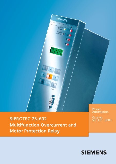
Fig. 1 <strong>SIPROTEC</strong> <strong>7SJ602</strong><br />
multifunction protection relay<br />
Hardware<br />
� 4 current transformers or<br />
� 3 current + 1 voltage transformers<br />
� 3 binary inputs<br />
� 2 output relays (NC or NO)<br />
� 2 output relays NO<br />
� 1 live status contact<br />
� Flush-/surface-mounting<br />
housing<br />
LSP2136-afpen.eps
Wide range of applications<br />
The <strong>SIPROTEC</strong> <strong>7SJ602</strong> is a numerical<br />
overcurrent relay<br />
which, in addition to its primary<br />
use in radial distribution<br />
networks <strong>and</strong> motor protection,<br />
can also be employed as<br />
backup for feeder, transformer<br />
<strong>and</strong> generator differential<br />
protection.<br />
The <strong>SIPROTEC</strong> <strong>7SJ602</strong> provides<br />
definite-time <strong>and</strong> inverse-time<br />
overcurrent<br />
protection along with overload<br />
<strong>and</strong> negative sequence<br />
protection for a very comprehensive<br />
relay package. In this<br />
way, equipment such as motors<br />
can be protected against<br />
asymmetric <strong>and</strong> excessive<br />
loading. Asymmetric shortcircuits<br />
with currents that can<br />
be smaller than the largest<br />
possible load currents or<br />
phase interruptions are reliably<br />
detected.<br />
The integrated control function<br />
allows simple control of a<br />
circuit-breaker or disconnector<br />
(electrically operated/motorized<br />
switch) via the integrated<br />
HMI, DIGSI or SCADA.<br />
Fig. 2 Function diagram<br />
<strong>SIPROTEC</strong> <strong>7SJ602</strong> <strong>Multifunction</strong> <strong>Overcurrent</strong> <strong>and</strong> <strong>Motor</strong> <strong>Protection</strong> Relay<br />
ANSI No. IEC <strong>Protection</strong> functions<br />
50, 50N I>, I>>, I>>><br />
IE>, IE>><br />
Definite time-overcurrent protection (phase/neutral)<br />
Application<br />
51, 51N Ip, IEp Inverse time-overcurrent protection (phase/neutral)<br />
67Ns/50Ns IEE>, IEE>>, IEEp Directional/non-directional sensitive earth-fault detection<br />
64 VE> Displacement voltage<br />
50BF Breaker failure protection<br />
79 Auto-reclosure<br />
46 I2> Phase-balance current protection (negative-sequence protection)<br />
49 �> Thermal overload protection<br />
48 Starting time supervision<br />
66/86 Restart inhibit<br />
37 I< Undercurrent monitoring<br />
38 Temperature monitoring via external device,<br />
e.g. bearing temperature monitoring<br />
74TC Trip circuit supervision breaker control<br />
Siemens SIP 3.3 · 2003 3
<strong>SIPROTEC</strong> <strong>7SJ602</strong> <strong>Multifunction</strong> <strong>Overcurrent</strong> <strong>and</strong> <strong>Motor</strong> <strong>Protection</strong> Relay<br />
Construction/<strong>Protection</strong> Functions<br />
Construction<br />
The relay contains all the<br />
components needed for<br />
� Acquisition <strong>and</strong> evaluation<br />
of measured values<br />
� Operation <strong>and</strong> display<br />
� Output of signals <strong>and</strong> trip<br />
comm<strong>and</strong>s<br />
� Input <strong>and</strong> evaluation of binary<br />
signals<br />
� SCADA interface<br />
(RS485, RS232, fiber-optic)<br />
� Power supply.<br />
The rated CT currents applied<br />
to the <strong>SIPROTEC</strong> <strong>7SJ602</strong> can<br />
be 1 A or 5 A. This is selectable<br />
via a jumper inside the<br />
relay.<br />
Two different housings are<br />
available. The flush-mounting<br />
version has terminals accessible<br />
from the rear. The surface-mounting<br />
version has<br />
terminals accessible from the<br />
front. Retrofitting of a communication<br />
module, or replacement<br />
of an existing<br />
communication module with<br />
a new one are both possible.<br />
Fig. 3<br />
Rear view of flush-mounting<br />
housing<br />
Fig. 4<br />
View from below showing<br />
system interface (SCADA)<br />
with FO connection (for remote<br />
communications)<br />
4 Siemens SIP 3.3 · 2003<br />
LSP2137-afpen.eps<br />
LSP2138-afpen.eps<br />
<strong>Protection</strong> functions<br />
Definite-time characteristics<br />
The definite-time overcurrent<br />
function is based on phaseselective<br />
evaluation of the<br />
three phase currents <strong>and</strong><br />
earth current.<br />
The definite-time overcurrent<br />
protection for the 3 phase<br />
currents has a low-set<br />
overcurrent element (I>), a<br />
high-set overcurrent<br />
element (I>>) <strong>and</strong> a high-set<br />
instantaneous element (I>>>).<br />
Intentional trip delays can be<br />
set from 0 to 60 seconds for<br />
the low-set <strong>and</strong> high-set<br />
overcurrent elements.<br />
The instantaneous zone I>>><br />
trips without any intentional<br />
delay. The definite-time<br />
overcurrent protection for the<br />
earth (ground) current has a<br />
low-set overcurrent element<br />
(IE>) <strong>and</strong> a high-set<br />
overcurrent element (IE>>).<br />
Intentional trip delays can be<br />
parameterized from 0 to 60<br />
seconds.<br />
Inverse-time chracteristics<br />
In addition, inverse-time<br />
overcurrent protection characteristics<br />
(IDMTL) can be activated.<br />
Reset characteristics<br />
For easier time coordination<br />
with electromechanical relays,<br />
reset characteristics according<br />
to ANSI C37.112 <strong>and</strong><br />
IEC 60255-3 /BS 142 st<strong>and</strong>ards<br />
are applied. When using<br />
the reset characteristic (disk<br />
emulation), a reset process is<br />
initiated after the fault current<br />
has disappeared.<br />
Fig. 5 Definite-time overcurrent characteristic<br />
Fig. 6 Inverse-time overcurrent characteristic<br />
This reset process corresponds<br />
to the reverse movement<br />
of the Ferraris disk of an<br />
electromechanical relay (thus:<br />
disk emulation).<br />
Available inverse-time characteristics<br />
Characteristics acc. to ANSI/IEEE IEC 60255-3<br />
Inverse � �<br />
Short inverse �<br />
Long inverse � �<br />
Moderately inverse �<br />
Very inverse � �<br />
Extremely inverse � �<br />
Definite inverse �<br />
I squared T<br />
RI/RD-type<br />
�
(Sensitive) directional earthfault<br />
detection<br />
(ANSI 64, 67Ns)<br />
The direction of power flow in<br />
the zero sequence is calculated<br />
from the zero-sequence<br />
current I0 <strong>and</strong> zero-sequence<br />
voltage V0. For networks with<br />
an isolated neutral, the reactive<br />
current component is<br />
evaluated; for compensated<br />
networks the active current<br />
component or residual resistive<br />
current is evaluated. For<br />
special network conditions,<br />
e.g. high-resistance earthed<br />
networks with ohmic-capacitive<br />
earth-fault current or<br />
low-resistance earthed networks<br />
with ohmic-inductive<br />
current, the tripping characteristics<br />
can be rotated approximately<br />
± 45 degrees<br />
(cosine/sinus).<br />
Two modes of earth-fault direction<br />
detection can be implemented:<br />
tripping or in<br />
“signalling only mode”.<br />
It has the following functions:<br />
� TRIP via the displacement<br />
voltage VE.<br />
� Two instantaneous elements<br />
or one instantaneous<br />
plus one inverse characteristic.<br />
� Each element can be set in<br />
forward, reverse, or nondirectional.<br />
(Sensitive) earth-fault<br />
detection<br />
(ANSI 50Ns, 51Ns / 50N, 51N)<br />
For high-resistance earthed<br />
networks, a sensitive input<br />
transformer is connected to a<br />
phase-balance neutral current<br />
transformer (also called<br />
core-balance CT).<br />
Thermal overload protection<br />
(ANSI49)<br />
The thermal overload protection<br />
function provides tripping<br />
or alarming based on a<br />
thermal model calculated<br />
from phase currents.<br />
The ambient temperature or<br />
the temperature of the coolant<br />
can be detected serially<br />
via an external temperature<br />
monitoring box (also called<br />
thermo-box). If there is no<br />
thermo-box it is assumed that<br />
the ambient temperatures are<br />
constant.<br />
Thermal overload protection<br />
without preload:<br />
For thermal overload protection<br />
without consideration of<br />
the preload current, the following<br />
tripping characteristic<br />
applies only when<br />
I � 1.1 · IL<br />
For different thermal time<br />
constants TL, the tripping<br />
time t is calculated in accordance<br />
with the following<br />
equation:<br />
35<br />
t � �T<br />
2<br />
� �<br />
� I �<br />
� � �1<br />
�I<br />
�<br />
L<br />
I = Load current<br />
IL = Pickup current<br />
TL = Time multiplier<br />
The reset threshold is above<br />
1.03125 · I/IN<br />
L<br />
<strong>SIPROTEC</strong> <strong>7SJ602</strong> <strong>Multifunction</strong> <strong>Overcurrent</strong> <strong>and</strong> <strong>Motor</strong> <strong>Protection</strong> Relay<br />
<strong>Protection</strong> Functions<br />
Fig. 7 Directional determination using cosine measurements<br />
Thermal overload protection<br />
with preload<br />
The thermal overload protection<br />
with consideration of<br />
preload current constantly updates<br />
the thermal model calculation<br />
regardless of the<br />
magnitude of the phase currents.<br />
The tripping time t is<br />
calculated in accordance with<br />
the following tripping characteristic<br />
(complete memory in<br />
accordance with IEC 60255-8).<br />
2<br />
�<br />
� I � �<br />
�<br />
� � �� Ipre<br />
�<br />
�k�IN��k�I<br />
t ���ln 2<br />
� �<br />
� I �<br />
� � �1<br />
�k<br />
�I<br />
�<br />
N<br />
N<br />
2<br />
�<br />
�<br />
�<br />
�<br />
t = Tripping time after<br />
beginning of the<br />
thermal overload<br />
� = 35.5 · TL<br />
Ipre = Pre-load current<br />
I = Load current<br />
k = k factor (in accordance<br />
with IEC 60255-8)<br />
ln = Natural logarithm<br />
TL = Time multiplier<br />
IN = Rated (nominal) current<br />
Siemens SIP 3.3 · 2003 5
<strong>SIPROTEC</strong> <strong>7SJ602</strong> <strong>Multifunction</strong> <strong>Overcurrent</strong> <strong>and</strong> <strong>Motor</strong> <strong>Protection</strong> Relay<br />
<strong>Protection</strong> Functions<br />
Breaker failure protection<br />
(ANSI 50BF)<br />
If a faulted portion of the<br />
electrical circuit is not disconnected<br />
upon issuance of a trip<br />
comm<strong>and</strong>, another comm<strong>and</strong><br />
can be initiated using the<br />
breaker failure protection<br />
which operates the circuitbreaker,<br />
e.g., of an upstream<br />
(higher-level) protection relay.<br />
Breaker failure is detected<br />
if after a trip comm<strong>and</strong>, current<br />
is still flowing in the<br />
faulted circuit. As an option it<br />
is possible to make use of the<br />
circuit-breaker position indication.<br />
Negative-sequence protection<br />
(I2>>, I2>/ANSI 46 Unbalanced-load<br />
protection)<br />
The negative-sequence protection<br />
(see Fig. 8) detects a<br />
phase failure or load unbalance<br />
due to network asymmetry.<br />
Interruptions, shortcircuits<br />
or crossed<br />
connections to the current<br />
transformers are detected.<br />
Furthermore, low level single-phase<br />
<strong>and</strong> two-phase<br />
short-circuits (such as faults<br />
beyond a transformer) as well<br />
as phase interruptions can be<br />
detected.<br />
This function is especially useful<br />
for motors since negative<br />
sequence currents cause impermissible<br />
overheating of<br />
the rotor.<br />
In order to detect the unbalanced<br />
load, the ratio of negative<br />
phase-sequence current<br />
to rated current is evaluated.<br />
I2 = Negative-sequence<br />
current<br />
T12 = Tripping time<br />
6 Siemens SIP · 2003<br />
Transformer protection<br />
The high-set element permits<br />
current coordination where<br />
the overcurrent element functions<br />
as a backup for the<br />
lower-level protection relays,<br />
<strong>and</strong> the overload function<br />
protects the transformer from<br />
thermal overload. Lowcurrent<br />
single-phase faults on<br />
the low voltage side that result<br />
in negative phase-sequence<br />
current on the highvoltage<br />
side can be detected<br />
with the negative-sequence<br />
protection.<br />
Cold load pickup<br />
By means of a binary input<br />
which can be wired from a<br />
manual close contact, it is<br />
possible to switch the<br />
overcurrent pickup settings to<br />
less sensitive settings for a<br />
programmable duration of<br />
time. After the set time has<br />
expired, the pickup settings<br />
automatically return to their<br />
original setting. This can compensate<br />
for initial inrush<br />
when energizing a circuit<br />
without compromising the<br />
sensitivity of the overcurrent<br />
elements during steady state<br />
conditions.<br />
3-pole multishot autoreclosure<br />
(AR, ANSI 79)<br />
Auto-reclosure (AR) enables<br />
3-phase auto-reclosing of a<br />
feeder which has previously<br />
been disconnected by timeovercurrent<br />
protection.<br />
Trip circuit supervision<br />
(ANSI 74TC)<br />
One or two binary inputs can<br />
be used for the trip circuit<br />
monitoring.<br />
Control<br />
The relay permits circuitbreakers<br />
to be opened <strong>and</strong><br />
closed without comm<strong>and</strong><br />
feedback. The circuitbreaker/disconnector<br />
may be<br />
controlled by DIGSI, or by the<br />
integrated HMI, or by the<br />
LSA/SCADA equipment connected<br />
to the interface.<br />
Fig. 8 Tripping characteristics of the negative-sequence<br />
protection function
Switch-onto-fault protection<br />
If switched onto a fault, instantaneous<br />
tripping can be<br />
effected. If the internal control<br />
function is used (local, via<br />
binary input or via serial interface),<br />
the manual closing<br />
function is available without<br />
any additional wiring. If the<br />
control switch is connected to<br />
a circuit-breaker by-passing<br />
the internal control function,<br />
manual detection using a binary<br />
input is implemented.<br />
Busbar protection (Reverse<br />
interlocking)<br />
Binary inputs can be used to<br />
block any of the six current<br />
stages. Parameters are assigned<br />
to decide whether the<br />
input circuit is to operate in<br />
open-circuit or closed-circuit<br />
mode. In this case, reverse interlocking<br />
provides highspeed<br />
busbar protection in radial<br />
or ring power systems<br />
that are opened at one point.<br />
The reverse interlocking principle<br />
is used, for example, in<br />
medium-voltage power systems<br />
<strong>and</strong> in switchgear for<br />
power plants, where a<br />
high-voltage system transformer<br />
feeds a busbar section<br />
with several medium-voltage<br />
outgoing feeders.<br />
Fig. 9 Reverse interlocking<br />
<strong>SIPROTEC</strong> <strong>7SJ602</strong> <strong>Multifunction</strong> <strong>Overcurrent</strong> <strong>and</strong> <strong>Motor</strong> <strong>Protection</strong> Relay<br />
<strong>Protection</strong> Functions<br />
Siemens SIP 3.3 · 2003 7
<strong>SIPROTEC</strong> <strong>7SJ602</strong> <strong>Multifunction</strong> <strong>Overcurrent</strong> <strong>and</strong> <strong>Motor</strong> <strong>Protection</strong> Relay<br />
<strong>Protection</strong> Functions/Features<br />
<strong>Motor</strong> protection<br />
Starting time supervision<br />
(ANSI 48)<br />
Starting time supervision protects<br />
the motor against long<br />
unwanted startups that might<br />
occur when excessive load<br />
torque occurs, excessive voltage<br />
drops occur within the<br />
motor or if the rotor is locked.<br />
Rotor temperature is calculated<br />
from measured stator<br />
current. The tripping time is<br />
calculated according to the<br />
following equation:<br />
tTRIP = I �<br />
�<br />
�<br />
�I<br />
start<br />
rms<br />
2<br />
�<br />
�<br />
�<br />
� t<br />
�<br />
start max<br />
for Irms > Istart, reset ratio I<br />
approx. 0.94<br />
I<br />
tTRIP<br />
Istart<br />
N<br />
start<br />
= Tripping time<br />
= Start-up current of<br />
the motor<br />
tstart max = Maximum permissible<br />
starting time<br />
Irms<br />
= Actual current flowing<br />
Restart inhibit (ANSI 66/86)<br />
If a motor is started up too<br />
many times in succession, the<br />
rotor can be subject to thermal<br />
overload, especially the<br />
upper edges of the bars. The<br />
rotor temperature is calculated<br />
from the stator current<br />
<strong>and</strong> the temperature characteristic<br />
is shown in a schematic<br />
diagram. The reclosing<br />
lockout only permits startup of<br />
the motor if the rotor has sufficient<br />
thermal reserves for a<br />
complete start-up.<br />
Undercurrent monitoring<br />
(ANSI 37)<br />
With this function, a sudden<br />
drop in current, that can occur<br />
due to a reduced motor load,<br />
is detected. This can cause<br />
shaft breakage, no-load operation<br />
of pumps or fan failure.<br />
8 Siemens SIP 3.3 · 2003<br />
Fig. 10<br />
Fig. 11<br />
Temperature monitoring<br />
(ANSI 38)<br />
A thermo-box (temperature<br />
monitoring box) with a total<br />
of 6 measuring sensors can be<br />
used for temperature monitoring<br />
<strong>and</strong> detection by the<br />
protection relay. The thermal<br />
status of motors, generators<br />
<strong>and</strong> transformers can be monitored<br />
with this device. Additionally,<br />
the temperature of<br />
the bearings of rotating machines<br />
are monitored for limit<br />
value violation. The temperatures<br />
are being measured<br />
with the help of temperature<br />
detectors at various locations<br />
of the device to be protected.<br />
This data is transmitted to the<br />
protection relay via a thermobox<br />
(see “Accessories”).<br />
Additional functions<br />
Measured values<br />
The r.m.s. values are calculated<br />
from the acquired current<br />
<strong>and</strong> voltage along with<br />
the power factor, active <strong>and</strong><br />
reactive power. The following<br />
functions are available for<br />
measured value processing:<br />
� Currents IL1, IL2, IL3, IE, IEE<br />
(67Ns)<br />
� Voltages VL1, VE (67NS) if existing<br />
� Power Watts, Vars, VA/P,<br />
Q, S<br />
� Power factor (cos �),<br />
� Energy ± kWh, ± kVarh, forward<br />
<strong>and</strong> reverse power<br />
flow<br />
� Mean as well as minimum<br />
<strong>and</strong> maximum current, voltage<br />
<strong>and</strong> power values
With respect to communication,<br />
particular emphasis has<br />
been placed on high levels of<br />
flexibility, data integrity <strong>and</strong><br />
utilization of st<strong>and</strong>ards common<br />
in energy automation.<br />
The design of the communication<br />
modules permits interchangeability.<br />
Local PC interface<br />
The <strong>SIPROTEC</strong> <strong>7SJ602</strong> is fitted<br />
with an RS232 PC front port. A<br />
PC can be connected to ease<br />
setup of the relay using the<br />
Windows-based program<br />
DIGSI which runs under<br />
MS-Windows. It can also be<br />
used to evaluate up to 8<br />
oscillographic fault records,<br />
8 fault logs <strong>and</strong> 1 event log<br />
containing up to 30 events.<br />
System interface on bottom<br />
of the unit<br />
A communication module located<br />
on the bottom part of<br />
the unit incorporates optional<br />
equipment complements <strong>and</strong><br />
readily permits retrofitting. It<br />
assures the ability to comply<br />
with the requirements of different<br />
communication interfaces.<br />
This interface is used to carry<br />
out communication with a<br />
control or a protection system<br />
<strong>and</strong> supports a variety of communication<br />
protocols <strong>and</strong> interface<br />
designs, depending on<br />
the module connected.<br />
IEC 60870-5-103 protocol<br />
IEC 60870-5-103 is an internationally<br />
st<strong>and</strong>ardized protocol<br />
for the efficient communication<br />
in the protected area.<br />
IEC 60870-5-103 is supported<br />
by a number of protection device<br />
manufacturers <strong>and</strong> is<br />
used worldwide.<br />
PROFIBUS-DP<br />
PROFIBUS-DP is an industryrecognized<br />
st<strong>and</strong>ard for communications<br />
<strong>and</strong> is supported<br />
by a number of PLC <strong>and</strong> protection<br />
device manufacturers.<br />
Fig. 14 System solution/communication<br />
MODBUS RTU<br />
MODBUS RTU is an industryrecognized<br />
st<strong>and</strong>ard for communications<br />
<strong>and</strong> is supported<br />
by a number of PLC <strong>and</strong> protection<br />
device manufacturers.<br />
<strong>SIPROTEC</strong> <strong>7SJ602</strong> <strong>Multifunction</strong> <strong>Overcurrent</strong> <strong>and</strong> <strong>Motor</strong> <strong>Protection</strong> Relay<br />
Communication<br />
Fig. 12<br />
Electrical communication module<br />
(RS232 or RS485)<br />
Fig. 13<br />
Fiber-optic double ring communication<br />
module<br />
Siemens SIP 3.3 · 2003 9
<strong>SIPROTEC</strong> <strong>7SJ602</strong> <strong>Multifunction</strong> <strong>Overcurrent</strong> <strong>and</strong> <strong>Motor</strong> <strong>Protection</strong> Relay<br />
Typical Connections<br />
<strong>7SJ602</strong>1/<strong>7SJ602</strong>5<br />
10 Siemens SIP 3.3 · 2003<br />
Fig. 15 Connection of 4 CTs with measurement<br />
of the earth (ground) current<br />
Fig. 16 Connection of 3 CTs with residual<br />
connection for neutral fault<br />
CT connections<br />
Fig. 15 St<strong>and</strong>ard<br />
Phase current measured<br />
Earth current measured (e. g. core balance CT)<br />
Fig. 16 St<strong>and</strong>ard connection<br />
Connection of 3 CTs with residual connection<br />
for neutral fault<br />
Fig. 17 Isolated networks only<br />
Fig. 17 Connection of 2 CTs only for isolated or<br />
resonant-earthed (grounded) power systems
<strong>7SJ602</strong>2/<strong>7SJ602</strong>6<br />
Fig. 18 Connection of 3 CTs with measurement<br />
of the sensitive earth (ground) current<br />
Fig. 19 Connection of 3 CTs with<br />
directional earth (ground)-fault detection<br />
<strong>SIPROTEC</strong> <strong>7SJ602</strong> <strong>Multifunction</strong> <strong>Overcurrent</strong> <strong>and</strong> <strong>Motor</strong> <strong>Protection</strong> Relay<br />
Typical Connections<br />
Fig. 20 Connection of 3 CTs <strong>and</strong> 1 VT<br />
with measurement of the earth (ground)<br />
current <strong>and</strong> one phase voltage<br />
Fig. 21 Example of typical wiring<br />
Siemens SIP 3.3 · 2003 11
<strong>SIPROTEC</strong> <strong>7SJ602</strong> <strong>Multifunction</strong> <strong>Overcurrent</strong> <strong>and</strong> <strong>Motor</strong> <strong>Protection</strong> Relay<br />
Technical Data<br />
General unit data<br />
CT circuits<br />
Rated current IN<br />
1 or 5 A (settable)<br />
Option: sensitive earth-fault CT IEE < 1.6 A or < 8.0 A (settable)<br />
Rated frequency fN<br />
Power consumption<br />
Current input at IN = 1 A<br />
at IN = 5 A<br />
For sensitive earth-fault<br />
detection at 1 A<br />
Overload capability<br />
Thermal (r.m.s)<br />
Dynamic (pulse current)<br />
Overload capability if equipped<br />
with sensitive earth-fault current<br />
transformer<br />
Thermal (r.m.s.)<br />
Dynamic (impulse current)<br />
Voltage transformer<br />
Rated voltage VN<br />
50/60 Hz (selectable)<br />
< 0.1 VA<br />
< 0.3 VA<br />
Approx. 0.05 VA<br />
100 x IN for 1 s<br />
30 x IN for 10 s<br />
4 x IN continuous<br />
250 x IN one half cycle<br />
300 A for 1 s<br />
100 A for 10 s<br />
15 A continuous<br />
750 A (half cycle)<br />
100 to 125 V<br />
Power consumption at VN = 100 V < 0.3 VA per phase<br />
Overload capability in voltage<br />
path (phase-neutral voltage)<br />
Thermal (r.m.s.) 230 V continuous<br />
Power supply<br />
Power supply via integrated<br />
DC/DC converter<br />
Rated auxiliary voltage Vaux /<br />
permissible variations<br />
Superimposed AC voltage,<br />
peak-to-peak<br />
At rated voltage<br />
At limits of admissible voltage<br />
24/48 V DC/± 20 %<br />
60/110 V DC/± 20 %<br />
110/125/220/250 V DC/± 20 %<br />
115 V AC/- 20 %, + 15 %<br />
230 V AC/- 20 %, + 15 %<br />
� 12 %<br />
� 6 %<br />
Power consumption Approx. 3 to 6 W, depending on<br />
operational status <strong>and</strong> selected auxiliary<br />
voltage<br />
Bridging time during failure/<br />
short-circuit of auxiliary voltage<br />
Binary outputs<br />
� 50 ms at Vaux � 110 V AC/DC<br />
� 20 ms at Vaux � 24 V DC<br />
Trip relays 4 (configurable)<br />
Contacts per relay 1 NO/form A<br />
(Two contacts changeable to<br />
NC/form B, via jumpers)<br />
Switching capacity<br />
Make<br />
Break<br />
Switching voltage 250 V<br />
Permissible current<br />
Continuous<br />
For 0.5 s<br />
Permissible total current<br />
For common potential:<br />
Continuous<br />
For 0.5 s<br />
1000 W/VA<br />
30 VA, 40 W resistive<br />
25 VA with L/R � 50 ms<br />
5 A<br />
30 A<br />
5 A<br />
30 A<br />
Alarm relays 1<br />
Contacts per relay 1 NO/NC (form A/B)<br />
12 Siemens SIP 3.3 · 2003<br />
Binary outputs, cont’d<br />
Switching capacity<br />
Make<br />
Break<br />
Switching voltage 250 V<br />
1000 W/VA<br />
30 VA, 40 W resistive<br />
25 VA with L/R � 50 ms<br />
Permissible current 5 A continuous<br />
Binary inputs<br />
Number 3 (configurable)<br />
Operating voltage 24 to 250 V DC<br />
Current consumption,<br />
independent of operating voltage<br />
Pickup threshold, selectable via<br />
bridges<br />
Rated aux. voltage<br />
24/48/60/110 V DC Vpickup<br />
110/125/220/250 V DC Vpickup<br />
Approx. 1.8 mA<br />
� 19 V DC<br />
� 88 V DC<br />
Permissible maximum voltage 300 V DC<br />
Connection (with screws)<br />
Current terminals<br />
Connection ring cable lugs<br />
Wire size<br />
Direct connection<br />
Wire size<br />
Voltage terminals<br />
Connection ring cable lugs<br />
Wire size<br />
Direct connection<br />
Wire size<br />
Wmax = 11 mm, d1 = 5 mm<br />
2.0 - 5.3 mm 2 (AWG 14-10)<br />
Solid conductor, flexible lead,<br />
connector sleeve<br />
2.0 - 5.3 mm 2 (AWG 14-10)<br />
Wmax = 10 mm, d1 = 4 mm<br />
0.5 - 3.3 mm 2 (AWG 20-12)<br />
Solid conductor, flexible lead,<br />
connector sleeve<br />
0.5 - 3.3 mm 2 (AWG 20-12)<br />
Unit version<br />
Housing 7XP20 For dimensions please refer<br />
to dimension drawings<br />
Degree of protection<br />
acc. EN 60529<br />
For the device<br />
in surface-mounting housing<br />
in flush-mounting housing<br />
front<br />
rear<br />
For personal safety<br />
Weight<br />
Flush mounting/<br />
cubicle mounting<br />
Surface mounting<br />
IP 51<br />
IP 51<br />
IP 20<br />
IP 2x with closed protection cover<br />
Approx. 4 kg<br />
Approx. 4.5 kg<br />
Serial interfaces<br />
Operating interface<br />
Connection At frontside, non-isolated, RS232,<br />
9-pin subminiature connector<br />
Operation With DIGSI 4.3 or higher<br />
Transmission speed As delivered 19200 baud, parity: 8E1<br />
Min. 1200 baud<br />
Max. 19200 baud<br />
Distance 15 m
Serial interfaces, cont’d<br />
System interface (bottom of unit)<br />
IEC 60870-5-103 protocol<br />
Connection Isolated interface for data transmission<br />
Transmission rate Min. 1200 baud, max. 19200 baud<br />
As delivered 9600 baud<br />
RS232/RS485 acc. to ordered<br />
version<br />
Connection 9-pin subminiature connector on the<br />
bottom part of the housing<br />
Test voltage 500 V AC<br />
RS232 maximum distance 15 m<br />
RS485 maximum distance 1000 m<br />
Fiber-optic<br />
Connector type ST connector on the bottom part<br />
of the housing<br />
Optical wavelength � = 820 nm<br />
Laser class 1 acc. to<br />
EN 60825-1/-2<br />
For glass fiber 50/125 µm<br />
or 62.5/125 µm<br />
Permissible path attenuation Max. 8 dB, for glass fiber 62.5/125 µm<br />
Bridgeable distance Max. 1.5 km<br />
No character position Selectable, setting as supplied<br />
„light off”<br />
PROFIBUS-DP<br />
Isolated interface for data transfer<br />
to a control center<br />
Transmission rate Up to 1.5 Mbaud<br />
Transmission reliability Hamming distance d = 4<br />
RS485<br />
Connection 9-pin subminiature connector<br />
Distance 1000 m/3300 ft � 93.75 kbaud;<br />
500 m/1500 ft � 187.5 kbaud;<br />
200 m/600 ft � 1.5 Mbaud<br />
Test voltage 500 V AC against earth<br />
Fiber optic<br />
Connection fiber-optic cable Integrated ST connector for fiberoptic<br />
connection<br />
Optical wavelength 820 nm<br />
Permissible path attenuation Max. 8 dB, for glass fiber 62.5/125 µm<br />
Distance 500 kB/s 1.6 km/0.99 miles<br />
1500 kB/s 530 m/0.33 miles<br />
Idle state of interface Settable, setting as supplied “light<br />
off”<br />
<strong>SIPROTEC</strong> <strong>7SJ602</strong> <strong>Multifunction</strong> <strong>Overcurrent</strong> <strong>and</strong> <strong>Motor</strong> <strong>Protection</strong> Relay<br />
System interface (bottom of unit), cont’d<br />
MODBUS RTU / ASCII<br />
Isolated interface for data transfer<br />
to a control center<br />
Transmission rate Up to 19200 baud<br />
Transmission reliability Hamming distance d = 4<br />
RS485<br />
Connection 9-pin subminiature connector<br />
Distance Max. 1 km/3300 ft max. 32 units<br />
recommended<br />
Test voltage<br />
Fiber-optic<br />
500 V AC against earth<br />
Connection fiber-optic cable Integrated ST connector for fiberoptic<br />
connection<br />
Optical wavelength 820 nm<br />
Permissible path attenuation Max. 8 dB, for glass fiber 62.5/125 µm<br />
Distance Max. 1.5 km/0.9 miles<br />
Idle state of interface “Light off”<br />
Electrical tests<br />
Specifications<br />
St<strong>and</strong>ards IEC 60255-5; ANSI/IEEE C37.90.0<br />
Insulating tests<br />
High-voltage tests (routine test)<br />
all circuits except for auxiliary<br />
voltage, binary inputs <strong>and</strong><br />
communication interfaces<br />
High-voltage tests (routine test)<br />
Auxiliary voltage <strong>and</strong> binary inputs<br />
High-voltage tests (routine test)<br />
only isolated communication<br />
interfaces<br />
Impulse voltage tests (type test)<br />
all circuits, except<br />
communication interfaces<br />
2.5 kV (r.m.s. value), 50 Hz<br />
3.5 kV DC<br />
500 V (r.m.s. value); 50 Hz<br />
EMC tests for interference immunity; type tests<br />
5 kV (peak value), 1.2/50 µs, 0.5 J,<br />
3 positive <strong>and</strong> 3 negative impulses at<br />
intervals of 5 s<br />
St<strong>and</strong>ards IEC 60255-6; IEC 60255-22,<br />
(product st<strong>and</strong>ard)<br />
EN 50082-2 (generic st<strong>and</strong>ard)<br />
DIN 57435 Part 303<br />
High-frequency test<br />
IEC 60255-22-1, class III<br />
<strong>and</strong> VDE 0435 Part 303, class III<br />
Discharge of static electricity<br />
IEC 60255-22-2 class IV<br />
EN 61000-4-2, class IV<br />
Irradiation with radio-frequency<br />
field, non-modulated<br />
IEC 60255-22-3 (Report), class III<br />
Irradiation with radio-frequency<br />
field, amplitude-modulated<br />
IEC 61000-4-3, class III<br />
Irradiation with radio-frequency<br />
field, pulse-modulated<br />
IEC 61000-4-3/ENV 50204,<br />
class III<br />
Technical Data<br />
2.5 kV (peak value); 1 MHz,<br />
� = 15 �s; 400 surges per s;<br />
test duration 2 s; Ri = 200 �<br />
8 kV contact discharge,<br />
15 kV air gap discharge,<br />
both polarities, 150 pF; Ri = 330 �<br />
10 V/m, 27 to 500 MHz<br />
10 V/m, 80 to 1000 MHz,<br />
AM 80 %; 1 kHz<br />
duration > 10 s<br />
10 V/m, 900 MHz,<br />
repetition frequency 200 Hz<br />
duty cycle 50 % PM<br />
Siemens SIP 3.3 · 2003 13
<strong>SIPROTEC</strong> <strong>7SJ602</strong> <strong>Multifunction</strong> <strong>Overcurrent</strong> <strong>and</strong> <strong>Motor</strong> <strong>Protection</strong> Relay<br />
Technical Data<br />
Electrical tests, cont’d<br />
EMC tests for interference immunity; type tests, cont’d<br />
Fast transients interference/bursts<br />
IEC 60255-22-4 <strong>and</strong><br />
IEC 61000-4-4, class IV<br />
Surge voltage IEC 61000-4-5, class III<br />
Auxiliary voltage<br />
Measuring inputs, binary<br />
inputs/outputs<br />
Conducted RF<br />
amplitude-modulated<br />
IEC 61000-4-6, class III<br />
Power frequency magnetic field<br />
IEC 61000-4-8, class IV<br />
IEC 60255-6<br />
Oscillatory surge withst<strong>and</strong><br />
capability<br />
ANSI/IEEE C37.90.1<br />
Fast transient surge withst<strong>and</strong><br />
capability<br />
ANSI/IEEE C37.90.1<br />
Radiated electromagnetic<br />
interference<br />
ANSI/IEEE Std C37.90.2<br />
Damped wave<br />
IEC 60694/ IEC 61000-4-12<br />
EMC tests interference emission; type tests<br />
4 kV; 5/50 ns; 5 kHz;<br />
burst length = 15 ms;<br />
repetition rate 300 ms;<br />
both polarities; Ri = 50 �;<br />
test duration 1 min<br />
1.2/50 µs<br />
From circuit to circuit (common<br />
mode): 2 kV, 12 �, 9 µF;<br />
Across contacts (diff. mode):<br />
1 kV, 2 �, 18 µF<br />
From circuit to circuit (common<br />
mode): 2 kV, 42 �, 0.5 µF;<br />
Across contacts (diff. mode):<br />
1 kV, 42 �, 0.5 µF<br />
10 V; 150 kHz to 80 MHz;<br />
AM 80 %; 1 kHz<br />
30 A/m continuous<br />
300 A/m for 3 s, 50 Hz<br />
0.5 mT, 50 Hz<br />
2.5 to 3 kV (peak value),<br />
1 to 1.5 MHz damped wave;<br />
50 surges per s; duration 2 s<br />
Ri = 150 to 200 �;<br />
4 to 5 kV, 10/150 ns,<br />
50 surges per s, both polarities;<br />
duration 2 s, Ri = 80 �;<br />
35 V/m; 25 to 1000 MHz;<br />
amplitude <strong>and</strong> pulse-modulated<br />
2.5 kV (peak value),<br />
polarity alternating<br />
100 kHz, 1 MHz, 10 <strong>and</strong> 50 MHz,<br />
Ri = 200 �;<br />
St<strong>and</strong>ard EN 50081-* (generic specification)<br />
Conducted interferences,<br />
only auxiliary voltage<br />
IEC/CISPR 22<br />
Radio interference field strength<br />
IEC/CISPR 22<br />
Harmonic currents on incoming<br />
lines of system at 230 V AC<br />
IEC 61000-3-2<br />
Voltage fluctuation <strong>and</strong> flicker<br />
range on incoming lines of system<br />
at 230 V AC<br />
IEC 61000-3-3<br />
14 Siemens SIP 3.3 · 2003<br />
150 kHz to 30 MHz<br />
limit class B<br />
30 to 1000 MHz<br />
limit class B<br />
Unit belongs to class D<br />
(applies only to units with > 50 VA<br />
power consumption)<br />
Limit values are adhered to<br />
Mechanical stress tests<br />
Vibration, shock <strong>and</strong> seismic vibration<br />
During operation<br />
St<strong>and</strong>ards Acc. to IEC 60255-21<br />
<strong>and</strong> IEC 60068-2<br />
Vibration<br />
IEC 60255-21-1, class I<br />
IEC 60068-2-6<br />
Shock<br />
IEC 60255-21-2, class I<br />
Seismic vibration<br />
IEC 60255-21-3, class I<br />
IEC 60068-3-3<br />
Sinusoidal<br />
10 to 60 Hz: ± 0.035 mm amplitude;<br />
60 to 150 Hz: 0.5 g acceleration<br />
Sweep rate 1 octave/min<br />
20 cycles in 3 orthogonal axes<br />
Half-sine,<br />
acceleration 5 g, duration 11 ms,<br />
3 shocks in each direction of<br />
3 orthogonal axes<br />
Sinusoidal<br />
1 to 8 Hz: ± 3.5 mm amplitude<br />
(horizontal axis)<br />
1 to 8 Hz: ± 1.5 mm amplitude<br />
(vertical axis)<br />
8 to 35 Hz: 1 g acceleration<br />
(horizontal axis)<br />
8 to 35 Hz: 0.5 g acceleration<br />
(vertical axis)<br />
Sweep rate 1 octave/min<br />
1 cycle in 3 orthogonal axes<br />
During transportation<br />
St<strong>and</strong>ards Acc. to IEC 60255-21<br />
<strong>and</strong> IEC 60068-2<br />
Vibration<br />
IEC 60255-21-1, class II<br />
IEC 60068-2-6<br />
Shock<br />
IEC 60255-21-2, class I<br />
IEC 60068-2-27<br />
Continuous shock<br />
IEC 60255-21-2, class I<br />
IEC 60068-2-29<br />
Sinusoidal<br />
5 to 8 Hz: ± 7.5 mm amplitude;<br />
8 to 150 Hz: 2 g acceleration<br />
Sweep rate 1 octave/min<br />
20 cycles in 3 orthogonal axes<br />
Half-sine,<br />
acceleration 15 g, duration 11 ms;<br />
3 shocks in each direction of<br />
3 orthogonal axes<br />
Half-sine,<br />
acceleration 10 g, duration 16 ms,<br />
1000 shocks in each direction of<br />
3 orthogonal axes<br />
Climatic stress tests<br />
Temperatures<br />
Recommended temperature<br />
During operation –5 °C to +55 °C /23 °F to 131 °F,<br />
(> 55 °C decreased display contrast)<br />
Limit temperature<br />
During operation<br />
–20 °C to +70 °C /–4 °F to 158 °F<br />
During storage<br />
–25 °C to +55 °C /–13 °F to 131 °F<br />
During transport<br />
–25 °C to +70 °C /–13 °F to 158 °F<br />
(Storage <strong>and</strong> transport<br />
with st<strong>and</strong>ard works packaging)<br />
Humidity<br />
Permissible humidity stress:<br />
It is recommended to arrange the<br />
units is such a way that they are<br />
not exposed to direct sunlight or<br />
pronounced temperature changes<br />
that could cause condensation.<br />
Annual average: < 75 % relative<br />
humidity, on 56 days per year 95 %<br />
relative humidity, condensation<br />
not permissible!
CE conformity<br />
This product is in conformity with the Directives of the European Communities<br />
on the harmonization of the laws of the Member States relating<br />
to electromagnetic compatibility (EMC Council Directive<br />
89/336/EEC) <strong>and</strong> electrical equipment designed for use within certain<br />
voltage limits (Council Directive 73/23/EEC).<br />
This unit conforms to the international st<strong>and</strong>ard IEC 60255, <strong>and</strong> the<br />
German st<strong>and</strong>ard DIN 57435/Part 303 (corresponding to VDE 0435/<br />
Part 303).<br />
The unit has been developed <strong>and</strong> manufactured for application in an<br />
industrial environment according to the EMC st<strong>and</strong>ards.<br />
This conformity is the result of a test that was performed by Siemens AG<br />
in accordance with Article 10 of the Council Directive complying with<br />
the generic st<strong>and</strong>ards EN 50081-2 <strong>and</strong> EN 50082-2 for the EMC<br />
Directive <strong>and</strong> st<strong>and</strong>ard EN 60255-6 for the “low-voltage Directive”.<br />
Functions<br />
Definite-time overcurrent protection (ANSI 50, 50N)<br />
Setting ranges/steps<br />
Low-set overcurrent element<br />
Phase I><br />
Earth IE><br />
High-set overcurrent element<br />
Phase I>><br />
Earth IE>><br />
Instantaneous tripping<br />
Phase I>>><br />
Delay times T for I>, IE>, I>><br />
<strong>and</strong> IE>><br />
The set times are pure delay times<br />
Pickup times I>, I>>, IE>, IE>><br />
At 2 x setting value,<br />
without meas. repetition<br />
At 2 x setting value,<br />
with meas. repetition<br />
Pickup times for I>>><br />
at 2 x setting value<br />
Reset times I>, I>>, I>>>, IE>, IE>><br />
50 Hz<br />
60 Hz<br />
I/IN = 0.1 to 25 (steps 0.1); or �<br />
I/IN = 0.05 to 25 (steps 0.01); or �<br />
I/IN = 0.1 to 25 (steps 0.1); or �<br />
I/IN = 0.05 to 25 (steps 0.01); or �<br />
I/IN = 0.3 to 12.5 (steps 0.1); or �<br />
0 to 60 s (steps 0.01 s)<br />
Approx. 35 ms<br />
Approx. 55 ms<br />
Approx. 20 ms<br />
Approx. 65 ms<br />
Approx. 95 ms<br />
Reset ratios Approx. 0.95<br />
Overshot time<br />
Tolerances<br />
Approx. 55 ms<br />
Pickup values I>, I>>, I>>>, 5 % of setting value or 5 % of<br />
IE>, IE>><br />
rated value<br />
Delay times T<br />
Influencing variables<br />
Auxiliary voltage, range:<br />
1 % of setting value or 10 ms<br />
0.8 � Vaux/VauxN � 1.2<br />
Temperature, range:<br />
- 5 °C ��amb � 40 °C /<br />
23 °F ��amb � 104 °F<br />
Frequency, range<br />
0.98 � f/fN � 1.02<br />
0.95 � f/fN � 1.05<br />
Harmonics<br />
Up to 10 % of 3 rd harmonic<br />
Up to 10 % of 5 rd � 1 %<br />
� 0.5 %/10 K<br />
� 1.5 %<br />
� 2.5 %<br />
� 1%<br />
harmonic � 1 %<br />
<strong>SIPROTEC</strong> <strong>7SJ602</strong> <strong>Multifunction</strong> <strong>Overcurrent</strong> <strong>and</strong> <strong>Motor</strong> <strong>Protection</strong> Relay<br />
Inverse-time overcurrent protection (ANSI 51/51N)<br />
Setting ranges/steps<br />
Low-set overcurrent element<br />
Phase Ip<br />
Earth IEp<br />
Time multiplier for Ip, IEp<br />
(IEC charac.)<br />
Time multiplier for Ip, IEp<br />
(ANSI charac.)<br />
High-set overcurrent element<br />
Phase I>><br />
Earth IE>><br />
Instantaneous tripping<br />
Phase I>>><br />
Delay time TI>><br />
Tripping time characteristic<br />
acc. to IEC<br />
Pickup threshold<br />
Reset threshold,<br />
alternatively disk emulation<br />
Dropout time<br />
50 Hz<br />
60 HZ<br />
Tolerances<br />
Pickup values<br />
Timing period for 2 � I/Ip � 20<br />
<strong>and</strong> 0.5 � I/Ip � 24<br />
Influencing variables<br />
Auxiliary voltage, range:<br />
0.8 � Vaux/VauxN � 1.2<br />
Temperature, range:<br />
-5 °C ��amb � 40 °C /<br />
-23 °F ��amb � 104 °F<br />
Frequency, range:<br />
0.95 � f/fN � 1.05<br />
Tripping characteristic<br />
acc. to ANSI/IEEE<br />
Pickup threshold<br />
Dropout threshold,<br />
alternatively disk emulation<br />
Tolerances<br />
Pickup threshold<br />
Timing period for 2 � I/Ip � 20<br />
<strong>and</strong> 0.5 � I/Ip � 24<br />
Influencing variables<br />
Auxiliary voltage, range:<br />
0.8 � Vaux/VauxN � 1.2<br />
Temperature, range:<br />
-5 °C ��amb � 40 °C /<br />
23 °F ��amb � 104 °F<br />
Frequency, range:<br />
0.95 � f/fN � 1.05<br />
Technical Data<br />
I/IN = 0.1 to 4 (steps 0.1)<br />
I/IN = 0.05 to 4 (steps 0.01)<br />
Tp = 0.05 to 3.20 s (steps 0.01 s)<br />
D = 0.5 to 15.0 s (steps 0.1 s)<br />
I/IN = 0.1 to 25 (steps 0.1); or �<br />
I/IN = 0.05 to 25 (steps 0.01); or �<br />
I/IN = 0.3 to 12.5 (steps 0.1); or �<br />
0 to 60 s (steps 0.01 s)<br />
See page 4<br />
Approx. 1.1 x Ip<br />
Approx. 1.03 x Ip<br />
Approx. 50 ms<br />
Approx. 60 ms<br />
5 % of setting value or 5 % of<br />
rated value<br />
5 % of theoretical value � 2 %<br />
current tolerance; at least 30 ms<br />
� 1 %<br />
� 0.5 %/10 K<br />
� 8 %, referred to theoretical<br />
time value<br />
See page 4<br />
Approx. 1.06 x Ip<br />
Approx. 1.03 x Ip<br />
5 % of setting value or 5 % of<br />
rated value<br />
5 % of theoretical value<br />
� 2 % current tolerance at least<br />
30 ms<br />
� 1 %<br />
� 0.5 %/10 K<br />
� 8 %, referred to theoretical<br />
time value<br />
Siemens SIP 3.3 · 2003 15
<strong>SIPROTEC</strong> <strong>7SJ602</strong> <strong>Multifunction</strong> <strong>Overcurrent</strong> <strong>and</strong> <strong>Motor</strong> <strong>Protection</strong> Relay<br />
Technical Data<br />
Functions, cont’d<br />
(Sensitive) earth-fault protection (directional/non-directional)<br />
Definite-time earth-fault protection (ANSI 50Ns)<br />
Setting ranges/steps<br />
Low-set element IEE> I/IEEN = 0.003 to 1.5 (steps 0.001);<br />
or � (deactivated)<br />
High-set element IEE>> I/IEEN = 0.003 to 1.5 (steps 0.001);<br />
or � (deactivated)<br />
Delay times T for IEE> <strong>and</strong> IEE>><br />
Pickup times IEE>, IEE>><br />
0 to 60 s (steps 0.01 s)<br />
At 2 x setting value<br />
without meas. repetition<br />
Approx. 35 ms<br />
At 2 x setting value<br />
with meas. repetition<br />
Reset times IEE>, IEE>><br />
Approx. 55 ms<br />
At 50 Hz<br />
Approx. 65 ms<br />
At 60 Hz<br />
Approx. 95 ms<br />
Reset ratios Approx. 0.95<br />
Overshot time<br />
Tolerances<br />
Approx. 55 ms<br />
Pickup values IEE>, IEE>> 5 % of setting value or 5 % of<br />
rated value<br />
Delay times T<br />
Influencing variables<br />
Auxiliary voltage, range:<br />
1 % of setting value or 10 ms<br />
0.8 � Vaux/VauxN � 1.2<br />
Temperature, range:<br />
- 5 °C ��amb � 40 °C /<br />
23 °F ��amb � 104 °F<br />
Frequency, ranges:<br />
0.98 � f/fN � 1.02<br />
0.95 � f/fN � 1.05<br />
Harmonics<br />
Up to 10 % of 3 rd harmonic<br />
Up to 10 % of 5 rd � 1 %<br />
� 0.5 %/10 K<br />
� 1.5 %<br />
� 2.5 %<br />
� 1%<br />
harmonic � 1 %<br />
Inverse-time earth-fault protection (ANSI 51Ns)<br />
Setting ranges/steps<br />
Low-set element IEEp<br />
Time multiplier for IEEp<br />
(IEC characteristic)<br />
Time multiplier for IEEp<br />
(ANSI characteristic)<br />
High-set element IEE>><br />
Delay time T for IEE>><br />
Tripping time characteristic<br />
acc. to IEC<br />
Pickup threshold<br />
Reset threshold<br />
alternatively disk emulation<br />
Dropout time<br />
50 Hz<br />
60 Hz<br />
Tolerances<br />
Pickup values<br />
Timing period for 2 � I/IEEp � 20<br />
<strong>and</strong> 0.5 � I/IEEN � 24<br />
Influencing variables<br />
Auxiliary voltage, range:<br />
0.8 � Vaux/VauxN � 1.2<br />
Temperature, range:<br />
-5 °C ��amb � 40 °C /<br />
23 °F ��amb � 104 °F<br />
Frequency, range:<br />
0.95 � f/fN � 1.05<br />
16 Siemens SIP 3.3 · 2003<br />
I/IEEN = 0.003 to 1.4 (steps 0.001)<br />
Tp = 0.05 to 3.20 s (steps 0.01 s)<br />
D = 0.5 to 15 s (steps 0.1 s)<br />
I/IEEN = 0.003 to 1.5 (steps 0.001);<br />
or � (deactivated)<br />
0 to 60 s (steps 0.01 s)<br />
See page 4<br />
Approx. 1.1 x IEEp<br />
Approx. 1.03 x IEEp<br />
Approx. 50 ms<br />
Approx. 60 ms<br />
5 % of setting value or 5 % of rated<br />
value<br />
5 % of theoretical value � 2 %<br />
current tolerance; at least 30 ms<br />
� 1 %<br />
� 0.5 %/10 K<br />
� 8 %, referred to theoretical<br />
time value<br />
(Sensitive) earth-fault protection (directional/non-directional), cont’d<br />
Inverse-time earth-fault protection (ANSI 51Ns), cont’d<br />
Tripping characteristic acc. to<br />
ANSI/IEEE<br />
Pickup threshold<br />
Dropout threshold,<br />
alternatively disk emulation<br />
Tolerances<br />
Pickup threshold<br />
Timing period for 2 � I/IEEN � 20<br />
<strong>and</strong> 0.5 � I/IEEN � 24<br />
Influencing variables<br />
Auxiliary voltage, range:<br />
0.8 � Vaux/VauxN � 1.2<br />
Temperature, range:<br />
-5 °C ��amb � 40 °C /<br />
23 °F ��amb � 104 °F<br />
Frequency, range:<br />
0.95 � f/fN � 1.05<br />
Direction detection (ANSI 67Ns)<br />
Direction measurement<br />
IE, VE (measured)<br />
See page 4<br />
Approx. 1.06 x IEEp<br />
Approx. 1.03 x IEEp<br />
5 % of setting value or 5 % of<br />
rated value<br />
5 % of theoretical value<br />
� 2 % current tolerance; at least<br />
30 ms<br />
� 1 %<br />
� 0.5 %/10 K<br />
� 8 %, referred to theoretical<br />
time value<br />
Measuring principle Active/reactive measurement<br />
Measuring enable<br />
For sensitive input 0.003 to 1.2 I/IEEN<br />
(in steps of 0.001 I/IEEN)<br />
Reset ratio<br />
Measuring method<br />
Approx. 0.80<br />
cos � <strong>and</strong> sin �<br />
Direction vector -45 ° to +45 ° (in steps of 0.1 °)<br />
Dropout delay<br />
1 to 60 s (steps 1 s)<br />
TReset Delay<br />
Angle correction for cable<br />
converter<br />
(for resonant-earthed system)<br />
In 2 operating points F1 <strong>and</strong> F2<br />
Angle correction F1, F2 0 ° to 5 ° (in steps of 0.1 °)<br />
Current values I1, I2<br />
For sensitive input I/IEEN = 0 0.003 to 1.6<br />
(in steps of 0.001 I/IEEN)<br />
Measuring tolerance<br />
acc. to DIN 57435<br />
Angle tolerance 3 °<br />
Displacement voltage (ANSI 64)<br />
2 % of the setting value or 1 mA<br />
Displacement voltage, measured VE >/VN = 0.02 to 1.3 (steps 0.001)<br />
Measuring time Approx. 60 ms<br />
Pickup delay time 0.04 to 320 s or � (steps 0.01 s)<br />
Time delay 0.10 to 40000 s or � (steps 0.01 s)<br />
Dropout ratio 0.95 or (pickup value -0.6 V)<br />
Measuring tolerance<br />
VE (measured) 3 % of setting value, or 0.3 V<br />
Operating time tolerances 1 % of setting value, or 10 ms<br />
The set times are pure delay times
Functions, cont’d<br />
Thermal overload protection with memory (ANSI 49) (with preload)<br />
Setting ranges<br />
Factor k according to IEC 60255-8 0.40 to 2 (steps 0.01)<br />
Thermal time constant �th<br />
Thermal warning stage<br />
�alarm/�trip<br />
Prolongation factor at motor<br />
st<strong>and</strong>-still k�<br />
Reset ratios<br />
�/�trip<br />
�/�alarm<br />
Tolerances<br />
Referring to k · IN<br />
Referring to trip time<br />
Influencing variables<br />
Auxiliary DC voltage, range<br />
0.8 � Vaux/VauxN � 1.2 � 1 %<br />
Temperature, range<br />
- 5 °C ��amb � + 40 °C /<br />
23 °F ��amb � 104 °F<br />
1 to 999.9 min (steps 0.1 min)<br />
50 to 99 % referred to trip<br />
temperature rise (steps 1 %)<br />
1 to 10 (steps 0.01)<br />
Reset below 0.99 �alarm<br />
Approx. 0.99<br />
± 5 %<br />
(class 5 % acc. to IEC 60255-8)<br />
± 5 % ± 2 s<br />
(class 5 % acc. to IEC 60255-8)<br />
� 0.5 %/10 K<br />
Frequency, range<br />
0.95 � f/fN � 1.05 � 1 %<br />
Thermal overload protection without memory (ANSI 49) (without<br />
preload)<br />
Setting ranges<br />
Pickup value IL/IN = 0.4 to 4 (steps 0.1)<br />
Time multiplier tL (= t6 -time) 1 to 120 s (steps 0.1 s)<br />
Reset ratio I/IL<br />
Tolerances<br />
Approx. 0.94<br />
Referring to pickup<br />
± 5 % of setting value or 5 %<br />
threshold 1.1 IL<br />
of rated value<br />
Referring to trip time<br />
Influencing variables<br />
Auxiliary DC voltage, range<br />
± 5 % ± 2 s<br />
0.8 � Vaux/VauxN � 1.2 � 1 %<br />
Temperature, range<br />
- 5 °C ��amb � + 40 °C /<br />
23 °F ��amb � 104 °F<br />
� 0.5 %/10 K<br />
Frequency, range<br />
0.95 � f/fN � 1.05 � 1 %<br />
Breaker failure protection<br />
Setting ranges/steps<br />
Pickup of current element CB I>/IN = 0.04 to 1.0 (steps 0.01)<br />
Delay time 0.06 to 60 s or � (steps 0.01 s)<br />
Pickup times (with internal start)<br />
(via control)<br />
(with external start)<br />
is contained in the delay time<br />
is contained in the delay time<br />
is contained in the delay time<br />
Dropout time<br />
Tolerances<br />
Approx. 25 ms<br />
Pickup value<br />
2 % of setting value<br />
Delay time<br />
1 % or 20 ms<br />
<strong>SIPROTEC</strong> <strong>7SJ602</strong> <strong>Multifunction</strong> <strong>Overcurrent</strong> <strong>and</strong> <strong>Motor</strong> <strong>Protection</strong> Relay<br />
Technical Data<br />
Negative-sequence protection (ANSI 46)<br />
Setting ranges/steps<br />
Tripping stages I2> <strong>and</strong> I2>> 8 to 80 % to IN (steps 1 %)<br />
Delay times T (I2>), T (I2>>) 0 to 60 s (steps 0.01 s)<br />
Lower function limit At least one phase current � 0.1 x IN<br />
Pickup times<br />
Tripping stages I2> <strong>and</strong> I2>><br />
But with currents I/IN > 1.5<br />
(overcurrent case) or negativesequence<br />
current < (set value<br />
+0.1 x IN)<br />
at fN = 50 Hz<br />
Approx. 60 ms<br />
Approx. 200 ms<br />
at fN = 60 Hz<br />
Approx. 75 ms<br />
Approx. 310 ms<br />
Reset times<br />
Tripping stages I2> <strong>and</strong> I2>> Approx. 35 ms Approx. 42 ms<br />
Reset ratios<br />
Tripping stages I2> <strong>and</strong> I2>> Approx. 0.9 to 0.01 x IN<br />
Tolerances<br />
Pickup values I2>, I2>><br />
current I/IN � 1.5<br />
current I/IN � 1.5<br />
± 1 % of IN ± 5 % of set value<br />
± 5 % of IN ± 5 % of set value<br />
Delay times T (I2>) <strong>and</strong> T (I2>>) ± 1 % but min. 10 ms<br />
Influencing variables<br />
Auxiliary DC voltage, range<br />
0.8 � Vaux/VauxN � 1.2 � 1 %<br />
Temperature, range<br />
–5 °C ��amb +40 °C /<br />
23 °F ��amb � 104 °F<br />
Frequency, range<br />
0.98 � f/fN � 1.02<br />
0.95 � f/fN � 1.05<br />
Auto-reclosure (ANSI 79)<br />
� 0.5 %/10 K<br />
� 1 % of IN<br />
� 5 % of IN<br />
Number of possible shots 1 to 9, configurable<br />
Auto-reclosure modes 3-pole<br />
Dead times for 1 st <strong>and</strong> any<br />
further shot<br />
0.05 s to 1800 s (steps 0.01 s)<br />
Blocking time after successful AR 0.05 s to 320 s (steps 0.01 s)<br />
Lock-out time after unsuccessful<br />
AR<br />
0.05 s to 320 s (steps 0.01 s)<br />
Reclaim time after manual close 0.50 s to 320 s (steps 0.01 s)<br />
Duration of reclose comm<strong>and</strong> 0.01 s to 60 s (steps 0.01 s)<br />
Trip circuit supervision (ANSI 74TC)<br />
Trip circuit supervision With one or two binary inputs<br />
Circuit-breaker trip test Trip/reclosure cycle<br />
Control<br />
Number of devices 1<br />
Evaluation of breaker contact None<br />
Siemens SIP 3.3 · 2003 17
<strong>SIPROTEC</strong> <strong>7SJ602</strong> <strong>Multifunction</strong> <strong>Overcurrent</strong> <strong>and</strong> <strong>Motor</strong> <strong>Protection</strong> Relay<br />
Technical Data<br />
<strong>Motor</strong> protection<br />
Setting ranges/steps<br />
Rated motor current/<br />
transformer rated current Imotor/IN = 0.2 to 1.2<br />
(in steps of 0.1)<br />
Start-up current of the motor Istart/Imotor = 0.4 to 20<br />
(in steps of 0.1)<br />
Permissible start-up time tstart max<br />
Starting time supervision (ANSI 48)<br />
1 to 360 s (in steps of 0.1 s)<br />
Setting ranges/steps<br />
Pickup threshold Ipickup/Imotor = 0.4 to 20<br />
(in steps of 0.1)<br />
Tripping time characteristic<br />
2<br />
start<br />
tTRIP �<br />
start max<br />
rms<br />
� �<br />
� �<br />
� �<br />
� �<br />
�<br />
I<br />
t<br />
I<br />
Reset ratio Irms/Istart<br />
For Irms > Ipickup<br />
Istart = Start-up current of the<br />
motor<br />
Irms = Current actually flowing<br />
Ipickup = Pickup threshold, from<br />
which the motor start-up<br />
is detected<br />
tstart max = Maximum permissible<br />
starting time<br />
tTRIP = Tripping time<br />
Approx. 0.94<br />
Tolerances<br />
Pickup values<br />
5 % of setting value or 5 % rated<br />
value<br />
Delay time<br />
5 % or 330 ms<br />
Restart inhibit for motors (ANSI 66/86)<br />
Setting ranges/steps<br />
Rotor temperature compensation<br />
time TCOMP<br />
Minimum restart inhibit<br />
time Trestart<br />
Maximum permissible number<br />
of warm starts nw<br />
Difference between cold <strong>and</strong><br />
warm start nc - nw<br />
Extension factor for cooling<br />
simultation of the rotor<br />
(running <strong>and</strong> stop)<br />
0 to 60 min (in steps of 0.1min)<br />
0.2 to 120 min (in steps of 0.1 min)<br />
1 to 4 (in steps of 1)<br />
1 to 2 (in steps of 1)<br />
1 to 10 (in steps of 0.1)<br />
Restarting limit � � �<br />
�<br />
restart rot max perm<br />
� n c<br />
Undercurrent monitoring (ANSI 37)<br />
1<br />
n c<br />
�restart = Temperature limit<br />
below which restarting<br />
is possible<br />
�rot max perm = Maximum permissible<br />
rotor overtemperature<br />
(= 100 % in operational<br />
measured value<br />
�rot/�rot trip)<br />
nc = Number of permissible<br />
start-ups from cold<br />
state<br />
Threshold IL < /IN = 0.1 to 4 (in steps of 0.01)<br />
Delay time for IL< 0 to 320 s (in steps of 0.1 s)<br />
18 Siemens SIP 3.3 · 2003<br />
Thermo-box (instead of system interface) (ANSI 38)<br />
Number of temperature sensors Max. 6<br />
Type of measuring Pt 100 � or Ni 100 � or Ni 120 �<br />
Installation drawing “Oil” or “Environment” or “Stator”<br />
or “Bearing” or “Other”<br />
Limit values for indications<br />
For each measuring detector<br />
Warning temperature<br />
(stage 1)<br />
Alarm temperature<br />
(stage 2)<br />
Additional functions<br />
Operational measured values<br />
For currents<br />
Range<br />
Tolerance<br />
For voltages<br />
Range<br />
Tolerance<br />
For sensitive earth-current<br />
detection<br />
Range<br />
Tolerance<br />
Power/work<br />
-50 °C to 250 °C (in steps of 1 °C)<br />
-58 °F to 482 °F (in steps of 1 °F)<br />
or � (no indication)<br />
-50 °C to 250 °C (in steps of 1 °C)<br />
-58 °F to 482 °F (in steps of 1 °F)<br />
or � (no indication)<br />
IL1, IL2, IL3, IE<br />
in A (Amps) primary or in % IN<br />
10 to 240 % IN<br />
3 % of measured value<br />
VL1-E, in kV primary or in %<br />
10 to 120 % of VN<br />
� 3 % of measured value<br />
IEE, IEEac, IEEreac<br />
(r.m.s., active <strong>and</strong> reactive current)<br />
in A (kA) primary, or in %<br />
0 to 160 % IEEN<br />
� 3 % of measured value<br />
S Apparent power in kVA, MVA, GVA<br />
S/VA (apparent power) For V/VN, I/IN = 50 to 120 %<br />
typically < 6 %<br />
P Active power, in kW, MW, GW<br />
P/Watts (active power) For |cos �| = 0.707 to 1 typically<br />
< 6 %, for V/VN, I/IN = 50 to 120 %<br />
Q Reactive power, In kvar, Mvar, Gvar<br />
Q/Var (reactive power) For |sin �| = 0.707 to 1 typically<br />
< 6 %, for V/VN, I/IN = 50 to 120 %<br />
cos �, total <strong>and</strong> phase-selective -1 to +1<br />
Power factor cos � For |cos �| = 0.707 to 1 typically<br />
< 5 %<br />
Metering<br />
+Wp kWh<br />
-Wp kWh<br />
+Wq kvarh<br />
-Wq kvarh<br />
In kWh, MWh, GWh forward<br />
In kWh reverse<br />
In kvarh inductive<br />
In kvarh, Mvarh, Gvarh capacitive<br />
Optional measured values<br />
Mean values 15, 30, 60 minutes mean values<br />
Long-term mean values<br />
IL1 dmd<br />
in A, kA<br />
IL2 dmd<br />
in A, kA<br />
in A, kA<br />
IL3 dmd<br />
Pdmd<br />
Qdmd<br />
Sdmd<br />
in kW<br />
in kvar<br />
in kVA
Additional functions, cont’d<br />
Min/max. LOG (memory)<br />
Measured values With date <strong>and</strong> time<br />
Reset automatic Time of day (settable in minutes)<br />
Time range (settable in days;<br />
1 to 365, �)<br />
Reset manual Via binary input<br />
Via keyboard<br />
Via communication<br />
Min./max. values of primary cur- IL1; IL2; IL3<br />
rents<br />
Min./max. values of primary volt- VL1-E<br />
ages<br />
Min./max. values of power S Apparent Power<br />
P Active power<br />
Q Reactive power<br />
Power factor cos �<br />
Min./max. values of primary currents<br />
mean values<br />
IL1dmd, IL2dmd, IL3dmd<br />
Min./max. values of power mean<br />
value<br />
Pdmd, Qdmd, Sdmd<br />
Fault event log<br />
Storage Storage of the last 8 faults<br />
Time assignment<br />
Resolution for operational 1 s<br />
indications<br />
Resolution for fault event 1 ms<br />
indications<br />
Max. time deviation<br />
0.01 %<br />
Fault recording<br />
Storage Storage of max. 8 fault events<br />
Total storage time (fault detection Max. 5 s, selectable pre-trigger <strong>and</strong><br />
or trip comm<strong>and</strong> = 0 ms)<br />
post-fault time<br />
Max. storage period per fault 0.30 s to 5.00 s (steps 0.01 s)<br />
event Tmax<br />
Pre-trigger time Tpre<br />
0.05 s to 0.50 s (steps 0.01 s)<br />
Post-fault time Tpost<br />
0.05 s to 0.50 s (steps 0.01 s)<br />
Sampling rate at 50 Hz<br />
1 instantaneous value per ms<br />
Sampling rate at 60 Hz<br />
1 instantaneous value per 0.83 ms<br />
Backup battery Lithium battery 3 V/1 Ah,<br />
type CR ½ AA<br />
Self-discharge time > 5 years<br />
“Battery fault” battery charge warning<br />
<strong>SIPROTEC</strong> <strong>7SJ602</strong> <strong>Multifunction</strong> <strong>Overcurrent</strong> <strong>and</strong> <strong>Motor</strong> <strong>Protection</strong> Relay<br />
Technical Data<br />
Siemens SIP 3.3 · 2003 19
<strong>SIPROTEC</strong> <strong>7SJ602</strong> <strong>Multifunction</strong> <strong>Overcurrent</strong> <strong>and</strong> <strong>Motor</strong> <strong>Protection</strong> Relay<br />
Selection <strong>and</strong> Ordering Data<br />
Description Order No. Order code<br />
<strong>SIPROTEC</strong> <strong>7SJ602</strong> <strong>7SJ602</strong>�-�����-���� + ���<br />
<strong>Multifunction</strong> overcurrent <strong>and</strong> motor protection relay<br />
Measuring inputs (4 x I), default settings<br />
IN = 1 A, 15th position only with A 1<br />
IN = 5 A, 15th position only with A 5<br />
Measuring inputs (1 x V, 3 x I), default settings<br />
Iph = 1 A, Ie = sensitive (IEE = 0.003 to 1.5 A), 15th position only with B <strong>and</strong> J 2<br />
Iph = 5 A, Ie = sensitive (IEE = 0.015 to 7.5 A), 15th position only with B <strong>and</strong> J 6<br />
Auxiliary voltage<br />
24/48 V DC, binary input threshold 19 V 2) 2<br />
60/110 V DC 1) , binary input threshold 19 V 2) 4<br />
110/125/220/250 V DC, 115/230 V AC 1) binary input threshold 88 V 2) 5<br />
Construction<br />
Surface-mounting housing, terminals on top <strong>and</strong> bottom B<br />
Flush-mounting housing, screw-type terminals E<br />
Region-specific default <strong>and</strong> language settings<br />
Region World, 50/60 Hz, ANSI/IEC characteristic, languages: English, German, French, Spanish, Russian B<br />
System port (on bottom of unit)<br />
No system port 0<br />
IEC 60870-5-103, electrical RS232 1<br />
IEC 60870-5-103, electrical RS485 2<br />
IEC 60870-5-103, optical 820 nm, ST connector 3<br />
Thermo-box, electrical RS485 3) 8<br />
PROFIBUS-DP Slave, electrical RS485 9 L 0 A<br />
PROFIBUS-DP Slave, optical, double ring, ST connector 9 L 0 B<br />
MODBUS, electrical RS485 9 L 0 D<br />
MODBUS, optical 820 nm, ST connector 9 L 0 E<br />
Comm<strong>and</strong> (without process check back signal)<br />
Without comm<strong>and</strong> 0<br />
With comm<strong>and</strong> 1<br />
Measuring / fault recording<br />
Oscillographic fault recording 1<br />
Oscillographic fault recording, slave pointer, mean values, min./max. values 3<br />
1) Transition between the two auxiliary<br />
voltage ranges can be selected by<br />
means of jumpers.<br />
2) The binary input thresholds can be selected<br />
in two stages by means of jumpers.<br />
3) Thermo-box 7XV5662-�AD10, refer to page 22.<br />
20 Siemens SIP 3.3 · 2003<br />
See next<br />
page
<strong>SIPROTEC</strong> <strong>7SJ602</strong> <strong>Multifunction</strong> <strong>Overcurrent</strong> <strong>and</strong> <strong>Motor</strong> <strong>Protection</strong> Relay<br />
Selection <strong>and</strong> Ordering Data<br />
Description Order No.<br />
<strong>SIPROTEC</strong> <strong>7SJ602</strong> <strong>7SJ602</strong>�-�����-����<br />
<strong>Multifunction</strong> overcurrent <strong>and</strong> motor protection relay<br />
ANSI No. Description<br />
Basic version<br />
50/51 Time-overcurrent protection TOC phase<br />
I>, I>>, Ip, reverse interlocking<br />
50N/51N Ground/earth-fault protection TOC ground/earth IE>, IE>>, IEp<br />
49 Overload protection<br />
74TC Trip circuit supervision<br />
50BF Breaker-failure protection<br />
Cold load pickup<br />
46 Negative sequence/unbalanced load protection FA 1)<br />
Basic version + directional ground/earth-fault detection<br />
50/51 Time-overcurrent protection TOC phase<br />
I>, I>>, Ip, reverse interlocking<br />
67Ns Directional sensitive ground/earth-fault detection IEE>, IEE>>, IEp<br />
64 Displacement voltage<br />
49 Overload protection<br />
74TC Trip circuit supervision<br />
50BF Breaker-failure protection<br />
Cold load pickup<br />
46 Negative sequence/unbalanced load protection FB 2)<br />
Basic version + sensitive ground/earth-fault detection + measuring<br />
50/51 Time-overcurrent protection TOC phase<br />
I>, I>>, Ip, reverse interlocking<br />
50Ns/51Ns Sensitive ground/earth-fault detection IEE>, IEE>>, IEp<br />
49 Overload protection<br />
74TC Trip circuit supervision<br />
50BF Breaker-failure protection<br />
Cold load pickup<br />
46 Negative sequence/unbalanced load protection<br />
Voltage <strong>and</strong> power measuring F J 2)<br />
Basic version + motor protection<br />
50/51 Time-overcurrent protection TOC phase<br />
I>, I>>, Ip, reverse interlocking<br />
50N/51N Ground/earth-fault protection TOC ground/earth IE>, IE>>, IEp<br />
49 Overload protection<br />
74TC Trip circuit supervision<br />
50BF Breaker-failure protection<br />
Cold load pickup<br />
46 Negative sequence/unbalanced load protection<br />
48 Starting time supervision<br />
37 Undercurrent/loss of load monitoring<br />
66/86 Restart inhibit HA 1)<br />
Basic version + directional ground/earth fault protection + motor protection<br />
50/51 Time-overcurrent protection TOC phase<br />
I>, I>>, Ip, reverse interlocking<br />
67Ns Directional sensitive ground/earth-fault detection IEE>, IEE>>, IEp<br />
64 Displacement voltage<br />
49 Overload protection<br />
74TC Trip circuit supervision<br />
50BF Breaker-failure protection<br />
Cold load pickup<br />
46 Negative sequence/unbalanced load protection<br />
48 Starting time supervision<br />
37 Undercurrent/loss of load monitoring<br />
66/86 Restart inhibit HB 2)<br />
Basic version + sensitive ground/earth-fault detection + measuring + motor protection<br />
50/51 Time-overcurrent protection TOC phase<br />
I>, I>>, Ip, reverse interlocking<br />
50Ns/51Ns Sensitive ground/earth-fault detection IEE>, IEE>>, IEp<br />
49 Overload protection<br />
74TC Trip circuit supervision<br />
50BF Breaker-failure protection<br />
Cold load pickup<br />
46 Negative sequence/unbalanced load protection<br />
Voltage <strong>and</strong> power measuring<br />
48 Starting time supervision<br />
37 Undercurrent/loss of load monitoring<br />
66/86 Restart inhibit H J 2)<br />
Auto-reclosure (ARC)<br />
Without auto-reclosure ARC 0<br />
79 With auto-reclosure ARC 1<br />
1) Only with position 7 = 1 or 5<br />
2) Only with position 7 = 2 or 6<br />
Siemens SIP 3.3 · 2003 21
<strong>SIPROTEC</strong> <strong>7SJ602</strong> <strong>Multifunction</strong> <strong>Overcurrent</strong> <strong>and</strong> <strong>Motor</strong> <strong>Protection</strong> Relay<br />
Accessories<br />
Short-circuit links<br />
for current terminals<br />
Mounting rail<br />
LSP2093-afp.eps<br />
22 Siemens SIP 3.3 · 2003<br />
LSP2289-afp.eps<br />
Description Order No.<br />
DIGSI 4<br />
Software for configuration <strong>and</strong> operation of Siemens protection units<br />
running under MS Windows (version Windows 95 <strong>and</strong> higher),<br />
device templates, Comtrade Viewer, electronic manual included<br />
as well as “Getting started” manual on paper, connecting cables (copper)<br />
Basis<br />
Full version with license for 10 computers, on CD-ROM<br />
(authorization by serial number) 7XS5400-0AA00<br />
Demo<br />
Demo version on CD-ROM 7XS5401-0AA00<br />
Professional<br />
Complete version:<br />
DIGSI 4 Basis <strong>and</strong> additionally SIGRA (fault record analysis),<br />
CFC Editor (logic editor), Display Editor (editor for default <strong>and</strong><br />
control displays) <strong>and</strong> DIGSI 4 Remote (remote operation) 7XS5402-0AA00<br />
SIGRA<br />
(generally contained in DIGSI Professional, but can be ordered additionally)<br />
Software for graphic visualization, analysis <strong>and</strong> evaluation of fault records.<br />
Can also be used for fault records of devices of other manufacturers<br />
(Comtrade format). Running under MS Windows.<br />
Incl. templates, electronic manual with license for 10 PCs on CD-ROM.<br />
Authorization by serial number. 7XS5410-0AA00<br />
Thermo-box (temperature monitoring box)<br />
24 to 60 V AC/DC 7XV5662-2AD10<br />
90 to 240 V AC/DC 7XV5662-5AD10<br />
Connecting cable (contained in DIGSI 4, but can be ordered additionally)<br />
Cable between PC/notebook (9-pin con.) <strong>and</strong> protection unit (9-pin connector) 7XV5100-4<br />
Cable between thermo-box <strong>and</strong> relay<br />
- Y-bus cable for RS485-bus with 9-pin connector (e.g. 1 m) 7XV5103-0AA01<br />
- adaptor cable to thermo-box with connector sleeve <strong>and</strong> 9-pin connector 7XV5103-2AA00<br />
Manual for <strong>7SJ602</strong><br />
English C53000-G1176-C125-4<br />
German C53000-G1100-C125-3<br />
Description Order No. Package size Supplier<br />
Terminal safety cover<br />
Voltage terminal 18-pole<br />
Current terminal 8-pole<br />
Short-circuit links<br />
For current terminals<br />
For other terminals<br />
C73334-A1-C31-1<br />
C73334-A1-C32-1<br />
C73334-A1-C33-1<br />
C73334-A1-C34-1<br />
1<br />
1<br />
1<br />
1<br />
Siemens<br />
Siemens<br />
Siemens<br />
Siemens<br />
Mounting rail for 19" rack C73165-A63-D200-1 1 Siemens<br />
Your local Siemens representative<br />
can inform you on local suppliers.
Fig. 22 Connection diagram<br />
<strong>SIPROTEC</strong> <strong>7SJ602</strong> <strong>Multifunction</strong> <strong>Overcurrent</strong> <strong>and</strong> <strong>Motor</strong> <strong>Protection</strong> Relay<br />
Connection Diagrams<br />
Siemens SIP 3.3 · 2003 23
<strong>SIPROTEC</strong> <strong>7SJ602</strong> <strong>Multifunction</strong> <strong>Overcurrent</strong> <strong>and</strong> <strong>Motor</strong> <strong>Protection</strong> Relay<br />
Connection Diagrams<br />
24 Siemens SIP 3.3 · 2003<br />
Fig. 23 Connection diagram
<strong>SIPROTEC</strong> <strong>7SJ602</strong> <strong>Multifunction</strong> <strong>Overcurrent</strong> <strong>and</strong> <strong>Motor</strong> <strong>Protection</strong> Relay<br />
Dimension Drawings<br />
View from the rear Side view / screw-type terminals<br />
Panel cutout<br />
Fig. 24<br />
<strong>7SJ602</strong> with 7XP20 housing<br />
for panel flush mounting/cubicle mounting,<br />
terminals at rear<br />
Fig. 25<br />
<strong>7SJ602</strong> with 7XP20 housing<br />
for panel surface mounting,<br />
terminals at top <strong>and</strong> bottom<br />
Siemens SIP 3.3 · 2003 25
<strong>SIPROTEC</strong> <strong>7SJ602</strong> <strong>Multifunction</strong> <strong>Overcurrent</strong> <strong>and</strong> <strong>Motor</strong> <strong>Protection</strong> Relay<br />
Appendix<br />
Notes<br />
If not stated otherwise on the individual<br />
pages of this catalog, we reserve the<br />
right to include modifications, especially<br />
regarding dimensions <strong>and</strong> weights.<br />
26 Siemens SIP 3.3 · 2003<br />
Drawings are not binding.<br />
All product designations used are trademarks<br />
or product names of Siemens AG<br />
or other suppliers.<br />
Catalog Index of the Power Transmission <strong>and</strong> Distribution Group (Power Automation Division)<br />
If not stated otherwise,<br />
all dimensions in this<br />
catalog are given in mm.<br />
Numerical <strong>Protection</strong> <strong>and</strong> Bay Control Units<br />
<strong>SIPROTEC</strong> Numerical <strong>Protection</strong> Relays SIP 2003 E50001-K4400-A101-A2-7600<br />
<strong>SIPROTEC</strong> Numerical <strong>Protection</strong> Relays (CD-ROM) SIP 2003 E50001-D4400-A107-A2-7600<br />
<strong>SIPROTEC</strong> 7SJ601 <strong>Overcurrent</strong> <strong>Protection</strong><br />
Auxiliary Current Transformers 4AM50, 4AM51, 4AM52<br />
LSA 2.1.16 E50001-K5712-A261-A1-7600<br />
<strong>and</strong> Isolating Transformers 7XR95 LSA 2.2.6 E50001-K5722-A161-A1-7600<br />
7XR96 Toroidal Current Transformer LSA 2.3.3 E50001-K5732-A131-A1-7600<br />
<strong>SIPROTEC</strong> <strong>7SJ602</strong> <strong>Multifunction</strong> <strong>Overcurrent</strong> <strong>and</strong> <strong>Motor</strong> <strong>Protection</strong> Relay<br />
<strong>SIPROTEC</strong> 4 7UT6 Differential <strong>Protection</strong> Relay for Transformers,<br />
SIP 3.3 E50001-K4403-A131-A2-7600<br />
Generators, <strong>Motor</strong>s <strong>and</strong> Busbars<br />
<strong>SIPROTEC</strong> 4 7UM62 <strong>Multifunction</strong> Generator, <strong>Motor</strong> <strong>and</strong> Transformer<br />
SIP 5.6 E50001-K4405-A161-A1-7600<br />
<strong>Protection</strong> Relay SIP 6.2 E50001-K4406-A121-A1-7600<br />
<strong>SIPROTEC</strong> 4 7VE61/63 <strong>Multifunction</strong> Paralleling Device SIP 6.3 Available on the Internet 1)<br />
6MB252 Mini Bay Unit for Energy Automation with SICAM <strong>SIPROTEC</strong> 7.1 E50001-K4407-A111-A1-7600<br />
Substation Control <strong>and</strong> <strong>Protection</strong><br />
Input/Output Unit 6MB522 LSA 1.1.1 E50001-K5701-A111-A4-7600<br />
Input/Output Unit 6MB523<br />
6MB513/514 Compact Control Master Unit<br />
LSA 1.1.2 E50001-K5701-A121-A2-7600<br />
<strong>and</strong> Relay Data Concentrator LSA 1.1.6 E50001-K5701-A161-A1-7600<br />
6MB524 Bay Control Unit LSA 1.1.7 E50001-K5701-A171-A2-7600<br />
6MB525 Mini Bay Unit (MBU) LSA 1.1.8 E50001-K5701-A181-A1-7600<br />
6MB5515 Station Control Unit LSA 1.2.6 E50001-K5701-A261-A1-7600<br />
LSADIAG - Testing <strong>and</strong> Diagnostics System for SINAUT LSA<br />
Substation Control <strong>and</strong> <strong>Protection</strong>-<br />
LSA 1.5.2 E50001-K5701-A521-A1-7600<br />
LSACONTROL - Control <strong>and</strong> Monitoring LSA 1.5.3 E50001-K5701-A531-A1-7600<br />
LSAPROCESS - Process Information Analysis LSA 1.5.5 E50001-K5701-A551-A1-7600<br />
LSAVIEW-Control <strong>and</strong> Monitoring in SINAUT LSA Substation Control<br />
<strong>and</strong> <strong>Protection</strong><br />
LSA 1.5.6 E50001-K5701-A561-A1-7600<br />
Energy Automation<br />
Substation SICAM RTU System SICAM 2.1.1 E50001-K5602-A111-A2-7600<br />
SICAM miniRTU 6MD202 Remote Terminal Unit SICAM 2.2.1 Available on the Internet 1)<br />
SICAM microRTU 6MD2030 Remote Terminal Unit SICAM 2.3.1 E50001-K5602-A311-A3-7600<br />
SICAM eRTU 6MD22 Substation SICAM 2.4.1 E50001-K5602-A411-A1-7600<br />
SICAM SAS Substation Automation System SICAM 3.1.1 E50001-K5603-A111-A1-7600<br />
PS20A-6EP8090 Power Supply Module SICAM 5.1.1 E50001-K5605-A111-A1-7600<br />
DI32-6MD1021 Digital Input Functional Module SICAM 5.2.1 E50001-K5605-A211-A1-7600<br />
AI32-6MD1031 Analog Input Functional Module SICAM 5.2.2 E50001-K5605-A221-A1-7600<br />
AI16-6MD1032 Analog Input Functional Module SICAM 5.2.3 E50001-K5605-A231-A1-7600<br />
CO32-6MD1022 Comm<strong>and</strong> Output Functional Module SICAM 5.3.1 E50001-K5605-A311-A1-7600<br />
CR-6MD 1023 Comm<strong>and</strong> Release Functional Module SICAM 5.3.2 E50001-K5605-A321-A1-7600<br />
Visualization System for SICAM SAS: SICAM WinCC SICAM 6.1.1 E50001-K5606-A111-A2-7600<br />
SICAM plusTOOLS Configuration System SICAM 6.2.1 E50001-K5606-A211-A1-7600<br />
1) On the Internet at: www.siprotec.de
Siemens SIP 3.3 · 2003 27
Responsible for<br />
Technical contents: Martin Berndsen<br />
Siemens AG, PTD PA 13, Nürnberg<br />
General editing: Claudia Kühn-Sutiono<br />
Siemens AG, PTD CC T, Erlangen<br />
28 Siemens SIP 3.3 · 2003 Printed in Germany Order No.: E50001-K4403-A131-A2-7600<br />
KGK 0903 3.0 28 EN 100736 6101/D6289
If you have any questions about<br />
Power Transmission <strong>and</strong> Distribution,<br />
our Customer Support Center<br />
is available around the clock<br />
Tel: +49 180 / 524 70 00<br />
Fax: +49 180 / 524 24 71<br />
E-Mail: support@ptd.siemens.de<br />
www.siemens.com/ptd-support<br />
Published by<br />
(Subject to charges,<br />
e.g.: 12 ct/min.)<br />
Siemens AG<br />
Power Transmission <strong>and</strong> Distribution<br />
Power Automation Division<br />
Postfach 48 06<br />
90026 Nuernberg<br />
Germany<br />
www.siemens.com/ptd Order No.: E50001-K4403-A131-A2-7600