LT3080 - Adjustable 1.1A Single Resistor Low Dropout Regulator
LT3080 - Adjustable 1.1A Single Resistor Low Dropout Regulator
LT3080 - Adjustable 1.1A Single Resistor Low Dropout Regulator

Create successful ePaper yourself
Turn your PDF publications into a flip-book with our unique Google optimized e-Paper software.
<strong>LT3080</strong><br />
APPLICATIO S I FOR ATIO<br />
able in higher values. Care still must be exercised when<br />
using X5R and X7R capacitors; the X5R and X7R codes<br />
only specify operating temperature range and maximum<br />
capacitance change over temperature. Capacitance change<br />
due to DC bias with X5R and X7R capacitors is better than<br />
Y5V and Z5U capacitors, but can still be signifi cant enough<br />
to drop capacitor values below appropriate levels. Capacitor<br />
DC bias characteristics tend to improve as component<br />
case size increases, but expected capacitance at operating<br />
voltage should be verifi ed.<br />
Voltage and temperature coeffi cients are not the only<br />
sources of problems. Some ceramic capacitors have a<br />
piezoelectric response. A piezoelectric device generates<br />
voltage across its terminals due to mechanical stress,<br />
similar to the way a piezoelectric microphone works. For a<br />
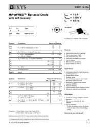
10<br />
CHANGE IN VALUE (%)<br />
20<br />
0<br />
–20<br />
–40<br />
–60<br />
–80<br />
U W U U<br />
BOTH CAPACITORS ARE 16V,<br />
1210 CASE SIZE, 10μF<br />
X5R<br />
Y5V<br />
–100<br />
0 2 4 6 8 10 12 14<br />
DC BIAS VOLTAGE (V)<br />
3080 F02<br />
Figure 2. Ceramic Capacitor DC Bias Characteristics<br />
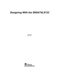
CHANGE IN VALUE (%)<br />
40<br />
20<br />
0<br />
–20<br />
–40<br />
–60<br />
Y5V<br />
X5R<br />
–80<br />
–100<br />
BOTH CAPACITORS ARE 16V,<br />
1210 CASE SIZE, 10μF<br />
–50 –25 0 25 50 75 100 125<br />
TEMPERATURE (°C)<br />
3080 F03<br />
Figure 3. Ceramic Capacitor Temperature Characteristics<br />
16<br />
ceramic capacitor the stress can be induced by vibrations<br />
in the system or thermal transients.<br />
Paralleling Devices<br />
<strong>LT3080</strong>’s may be paralleled to obtain higher output current.<br />
The SET pins are tied together and the IN pins are tied<br />
together. This is the same whether it’s in three terminal<br />
mode or has separate input supplies. The outputs are<br />
connected in common using a small piece of PC trace<br />
as a ballast resistor to equalize the currents. PC trace<br />
resistance in milliohms/inch is shown in Table 1. Only a<br />
tiny area is needed for ballasting.<br />
Table 1. PC Board Trace Resistance<br />
WEIGHT (oz) 10 mil WIDTH 20 mil WIDTH<br />
1 54.3 27.1<br />
2 27.1 13.6<br />
Trace resistance is measured in mOhms/in<br />
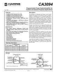
The worse case offset between the set pin and the output<br />
of only ± 2 millivolts allows very small ballast resistors<br />
to be used. As shown in Figure 4, the two devices have<br />
a small 10 milliohm ballast resistor, which at full output<br />
current gives better than 80 percent equalized sharing of<br />
the current. The external resistance of 10 milliohms (5<br />
VIN<br />
4.8V TO 28V<br />
1μF<br />
VIN<br />
V CONTROL<br />
V IN<br />
VCONTROL<br />
SET<br />
SET<br />
165k<br />
<strong>LT3080</strong><br />
+<br />
–<br />
<strong>LT3080</strong><br />
+<br />
–<br />
Figure 4. Parallel Devices<br />
OUT<br />
OUT<br />
10mΩ<br />
10mΩ<br />
3080 F04<br />
V OUT<br />
3.3V<br />
2A<br />
10μF<br />
3080f