LT3080 - Adjustable 1.1A Single Resistor Low Dropout Regulator
LT3080 - Adjustable 1.1A Single Resistor Low Dropout Regulator
LT3080 - Adjustable 1.1A Single Resistor Low Dropout Regulator

Create successful ePaper yourself
Turn your PDF publications into a flip-book with our unique Google optimized e-Paper software.
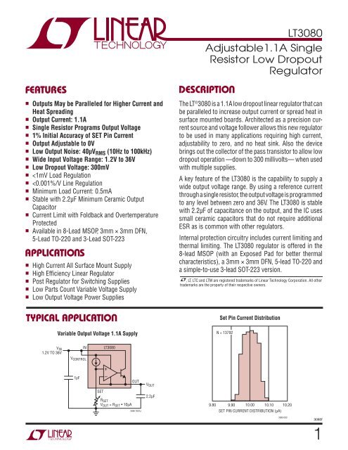
FEATURES DESCRIPTIO U<br />
■ Outputs May be Paralleled for Higher Current and<br />
Heat Spreading<br />
■ Output Current: <strong>1.1A</strong><br />
■ <strong>Single</strong> <strong>Resistor</strong> Programs Output Voltage<br />
■ 1% Initial Accuracy of SET Pin Current<br />
■ Output <strong>Adjustable</strong> to 0V<br />
■ <strong>Low</strong> Output Noise: 40μVRMS (10Hz to 100kHz)<br />
■ Wide Input Voltage Range: 1.2V to 36V<br />
■ <strong>Low</strong> <strong>Dropout</strong> Voltage: 300mV<br />
■
<strong>LT3080</strong><br />
ABSOLUTE AXI U RATI GS<br />
VCONTROL Pin Voltage ..................................... 40V, –0.3V<br />
IN Pin Voltage ................................................ 40V, –0.3V<br />
SET Pin Current (Note 7) .....................................±10mA<br />
SET Pin Voltage (Relative to OUT) .........................±0.3V<br />
Output Short-Circuit Duration .......................... Indefi nite<br />
2<br />
OUT<br />
OUT<br />
OUT<br />
SET<br />
W W W<br />
PIN CONFIGURATION<br />
TAB IS<br />
OUT<br />
1<br />
2<br />
3<br />
4<br />
TOP VIEW<br />
9<br />
U<br />
DD PACKAGE<br />
8-LEAD (3mm × 3mm) PLASTIC DFN<br />
TJMAX = 125°C, θJA = 64°C/W, θJC = 3°C/W<br />
EXPOSED PAD (PIN 9) IS OUT, MUST BE SOLDERED TO PCB<br />
FRONT VIEW<br />
5<br />
4<br />
3<br />
2<br />
1<br />
8<br />
7<br />
6<br />
5<br />
IN<br />
IN<br />
NC<br />
VCONTROL T PACKAGE<br />
5-LEAD PLASTIC TO-220<br />
TJMAX = 125°C, θJA = 40°C/W, θJC = 3°C/W<br />
ORDER INFORMATION<br />
IN<br />
VCONTROL<br />
OUT<br />
SET<br />
NC<br />
(Note 1)(All Voltages Relative to V OUT)<br />
Operating Junction Temperature Range<br />
(Notes 2, 10) .......................................... –40°C to 125°C<br />
Storage Temperature Range: .................. –65°C to 150°C<br />
Lead Temperature (Soldering, 10 sec)<br />
MS8E, T and ST Packages Only ........................ 300°C<br />
OUT<br />
OUT<br />
OUT<br />
SET<br />
1<br />
2<br />
3<br />
4<br />
TOP VIEW<br />
8 IN<br />
7 IN<br />
6 NC<br />
5 VCONTROL MS8E PACKAGE<br />
8-LEAD PLASTIC MSOP<br />
TJMAX = 125°C, θJA = 60°C/W, θJC = 10°C/W<br />
EXPOSED PAD (PIN 9) IS OUT, MUST BE SOLDERED TO PCB<br />
TAB IS<br />
OUT<br />
9<br />
FRONT VIEW<br />
3<br />
2<br />
1<br />
IN*<br />
OUT<br />
SET<br />
ST PACKAGE<br />
3-LEAD PLASTIC SOT-223<br />
*IN IS VCONTROL AND IN TIED TOGETHER<br />
TJMAX = 125°C, θJA = 55°C/W, θJC = 15°C/W<br />
LEAD FREE FINISH TAPE AND REEL PART MARKING PACKAGE DESCRIPTION TEMPERATURE RANGE<br />
<strong>LT3080</strong>EDD#PBF <strong>LT3080</strong>EDD#TRPBF LCBN 8-Lead (3mm × 3mm) Plastic DFN –40°C to 125°C<br />
<strong>LT3080</strong>EMS8E#PBF <strong>LT3080</strong>EMS8E#TRPBF LTCBM 8-Lead Plastic MSOP –40°C to 125°C<br />
<strong>LT3080</strong>ET#PBF <strong>LT3080</strong>ET#TRPBF <strong>LT3080</strong>ET 5-Lead Plastic TO-220 –40°C to 125°C<br />
<strong>LT3080</strong>EST#PBF <strong>LT3080</strong>EST#TRPBF 3080 3-Lead Plastic SOT-223 –40°C to 125°C<br />
LEAD BASED FINISH TAPE AND REEL PART MARKING PACKAGE DESCRIPTION TEMPERATURE RANGE<br />
<strong>LT3080</strong>EDD <strong>LT3080</strong>EDD#TR LCBN 8-Lead (3mm × 3mm) Plastic DFN –40°C to 125°C<br />
<strong>LT3080</strong>EMS8E <strong>LT3080</strong>EMS8E#TR LTCBM 8-Lead Plastic MSOP –40°C to 125°C<br />
<strong>LT3080</strong>ET <strong>LT3080</strong>ET#TR <strong>LT3080</strong>ET 5-Lead Plastic TO-220 –40°C to 125°C<br />
<strong>LT3080</strong>EST <strong>LT3080</strong>EST#TR 3080 3-Lead Plastic SOT-223 –40°C to 125°C<br />
Consult LTC Marketing for parts specifi ed with wider operating temperature ranges.<br />
For more information on lead free part marking, go to: http://www.linear.com/leadfree/<br />
For more information on tape and reel specifi cations, go to: http://www.linear.com/tapeandreel/<br />
3080f
ELECTRICAL CHARACTERISTICS<br />
<strong>LT3080</strong><br />
The ● denotes the specifi cations which apply over the full operating<br />
temperature range, otherwise specifi cations are at TA = 25°C. (Note 11)<br />
PARAMETER CONDITIONS MIN TYP MAX UNITS<br />
SET Pin Currrent ISET VIN = 1V, VCONTROL = 2.0V, ILOAD = 1mA, TJ = 25°C<br />
VIN ≥ 1V, VCONTROL ≥ 2.0V, 1mA ≤ ILOAD ≤ <strong>1.1A</strong> (Note 9) ●<br />
Output Offset Voltage (VOUT – VSET)<br />
VIN = 1V, VCONTROL = 2V, IOUT = 1mA<br />
VOS DFN and MSOP Package<br />
SOT-223 and T0-220 Package<br />
●<br />
●<br />
Load Regulation ΔISET<br />
ΔVOS<br />
Line Regulation (Note 9)<br />
DFN and MSOP Package<br />
Line Regulation (Note 9)<br />
SOT-223 and TO-220 Package<br />
ΔISET<br />
ΔVOS<br />
ΔI SET<br />
ΔVOS<br />
ΔILOAD = 1mA to <strong>1.1A</strong><br />
ΔI LOAD = 1mA to <strong>1.1A</strong> (Note 8) ●<br />
VIN = 1V to 25V, VCONTROL=1V to 25V, ILOAD=1mA<br />
V IN = 1V to 25V, VCONTROL=1V to 25V, ILOAD=1mA<br />
VIN = 1V to 26V, VCONTROL=1V to 26V, ILOAD=1mA<br />
V IN = 1V to 26V, VCONTROL=1V to 26V, ILOAD=1mA<br />
Minimum Load Current (Notes 3, 9) VIN = V CONTROL = 10V<br />
V IN = V CONTROL = 25V (DFN and MSOP Package)<br />
V IN = V CONTROL = 26V (SOT-223 and TO-220 Package)<br />
V CONTROL <strong>Dropout</strong> Voltage (Note 4) I LOAD = 100mA<br />
I LOAD = <strong>1.1A</strong> ●<br />
VIN <strong>Dropout</strong> Voltage (Note 4) ILOAD = 100mA<br />
ILOAD = <strong>1.1A</strong><br />
CONTROL Pin Current ILOAD = 100mA<br />
ILOAD = <strong>1.1A</strong><br />
9.90<br />
9.80<br />
–2<br />
–3.5<br />
–5<br />
–6<br />
10<br />
10<br />
● 0.1<br />
0.003<br />
● 0.1<br />
0.003<br />
●<br />
●<br />
●<br />
●<br />
●<br />
●<br />
●<br />
10.10<br />
10.20<br />
2<br />
3.5<br />
5<br />
6<br />
–0.1<br />
0.6 1.3<br />
300 500<br />
1<br />
1<br />
1.2<br />
1.35 1.6<br />
100<br />
350<br />
4<br />
17<br />
μA<br />
μA<br />
mV<br />
mV<br />
mV<br />
mV<br />
nA<br />
mV<br />
0.5 nA/V<br />
mV/V<br />
0.5 nA/V<br />
mV/V<br />
Current Limit VIN = 5V, VCONTROL = 5V, VSET = 0V, VOUT = –0.1V ● 1.1 1.4 A<br />
Error Amplifi er RMS Output Noise (Note 6) ILOAD = <strong>1.1A</strong>, 10Hz ≤ f ≤ 100kHz, COUT = 10μF, CSET = 0.1μF 40 μVRMS Reference Current RMS Output Noise (Note 6) 10Hz ≤ f ≤ 100kHz 1 nARMS Ripple Rejection f = 120Hz, VRIPPLE = 0.5VP-P, ILOAD = 0.2A, CSET = 0.1μF, COUT = 2.2μF<br />
f = 10kHz<br />
75<br />
55<br />
dB<br />
dB<br />
f = 1MHz<br />
20<br />
dB<br />
Thermal Regulation, ISET 10ms Pulse 0.003 %/W<br />
Note 1: Stresses beyond those listed under Absolute Maximum Ratings<br />
may cause permanent damage to the device. Exposure to any Absolute<br />
Maximum Rating condition for extended periods may affect device<br />
reliability and lifetime.<br />
Note 2: Unless otherwise specifi ed, all voltages are with respect to V OUT.<br />
The <strong>LT3080</strong> is tested and specifi ed under pulse load conditions such that<br />
T J ≈ TA. The <strong>LT3080</strong> is 100% tested at TA = 25°C. Performance at –40°C<br />
and 125°C is assured by design, characterization and correlation with<br />
statistical process controls.<br />
Note 3: Minimum load current is equivalent to the quiescent current of<br />
the part. Since all quiescent and drive current is delivered to the output<br />
of the part, the minimum load current is the minimum current required to<br />
maintain regulation.<br />
Note 4: For the <strong>LT3080</strong>, dropout is caused by either minimum control<br />
voltage (V CONTROL) or minimum input voltage (V IN). Both parameters are<br />
specifi ed with respect to the output voltage. The specifi cations represent the<br />
minimum input-to-output differential voltage required to maintain regulation.<br />
Note 5: The CONTROL pin current is the drive current required for the<br />
output transistor. This current will track output current with roughly a 1:60<br />
ratio. The minimum value is equal to the quiescent current of the device.<br />
Note 6: Output noise is lowered by adding a small capacitor across the<br />
voltage setting resistor. Adding this capacitor bypasses the voltage setting<br />
200<br />
500<br />
resistor shot noise and reference current noise; output noise is then equal<br />
to error amplifi er noise (see Applications Information section).<br />
Note 7: SET pin is clamped to the output with diodes. These diodes only<br />
carry current under transient overloads.<br />
Note 8: Load regulation is Kelvin sensed at the package.<br />
Note 9: Current limit may decrease to zero at input-to-output differential<br />
voltages (V IN–VOUT) greater than 25V (DFN and MSOP package) or 26V<br />
(SOT-223 and TO-220 package). Operation at voltages for both IN and<br />
V CONTROL is allowed up to a maximum of 36V as long as the difference<br />
between input and output voltage is below the specifi ed differential (V IN–<br />
V OUT) voltage. Line and load regulation specifi cations are not applicable<br />
when the device is in current limit.<br />
Note 10: This IC includes over-temperature protection that is intended<br />
to protect the device during momentary overload conditions. Junction<br />
temperature will exceed the maximum operating junction temperature<br />
when over-temperature protection is active. Continuous operation above<br />
the specifi ed maximum operating junction temperature may impair device<br />
reliability.<br />
Note 11: The SOT-223 package connects the IN and V CONTROL pins<br />
together internally. Therefore, test conditions for this pin follow the<br />
V CONTROL conditions listed in the Electrical Characteristics Table.<br />
6<br />
30<br />
μA<br />
mA<br />
mA<br />
V<br />
V<br />
mV<br />
mV<br />
mA<br />
mA<br />
3080f<br />
3
<strong>LT3080</strong><br />
TYPICAL PERFOR A CE CHARACTERISTICS<br />
SET PIN CURRENT (μA)<br />
CHANGE IN OFFSET VOLTAGE WITH LOAD (mV)<br />
10.20<br />
10.15<br />
10.10<br />
10.05<br />
10.00<br />
4<br />
9.95<br />
9.90<br />
9.85<br />
U W<br />
Set Pin Current Set Pin Current Distribution Offset Voltage (V OUT – V SET)<br />
9.80<br />
–50 –25 0 25 50 75 100 125 150<br />
TEMPERATURE (°C)<br />
0<br />
–0.1<br />
–0.2<br />
–0.3<br />
–0.4<br />
–0.5<br />
–0.6<br />
–0.7<br />
–2<br />
–0.8<br />
–50<br />
Offset Voltage Distribution<br />
N = 13250<br />
–1 0 1<br />
V OS DISTRIBUTION (mV)<br />
3080 G01<br />
2<br />
3080 G04<br />
9.90 10.00 10.10<br />
SET PIN CURRENT DISTRIBUTION (μA)<br />
Load Regulation Minimum Load Current<br />
ΔILOAD = 1mA TO <strong>1.1A</strong><br />
VIN – VOUT = 2V<br />
CHANGE IN REFERENCE CURRENT<br />
CHANGE IN OFFSET VOLTAGE<br />
(V OUT – V SET)<br />
–25 0 25 50 75 100 125<br />
TEMPERATURE (°C)<br />
3080 G07<br />
20<br />
10<br />
0<br />
–10<br />
–20<br />
–30<br />
–40<br />
–50<br />
–60<br />
150<br />
CHANGE IN REFERENCE CURRENT WITH LOAD (nA)<br />
OFFSET VOLTAGE (mV)<br />
1.00<br />
0.75<br />
0.50<br />
0.25<br />
–0.25<br />
9.80<br />
0<br />
–0.50<br />
–0.75<br />
–1.00<br />
0<br />
MINIMUM LOAD CURRENT (mA)<br />
0.8<br />
0.7<br />
0.6<br />
0.5<br />
0.4<br />
0.3<br />
0.2<br />
0.1<br />
N = 13792<br />
10.20<br />
3080 G02<br />
–2.0<br />
–50<br />
Offset Voltage Offset Voltage<br />
I LOAD = 1mA<br />
6 12 18 24 30<br />
INPUT-TO-OUTPUT VOLTAGE (V)<br />
*SEE NOTE 9 IN ELECTRICAL<br />
CHARACTERISTICS TABLE<br />
0<br />
–50<br />
V IN, CONTROL – V OUT = 36V*<br />
V IN, CONTROL – V OUT = 1.5V<br />
–25 0 25 50 75 100 125<br />
TEMPERATURE (°C)<br />
*SEE NOTE 9 IN ELECTRICAL<br />
CHARACTERISTICS TABLE<br />
3080 G05<br />
36*<br />
150<br />
3080 G08<br />
OFFSET VOLTAGE (mV)<br />
OFFSET VOLTAGE (mV)<br />
MINIMUM IN VOLTAGE (VIN – V OUT) (mV)<br />
2.0<br />
1.5<br />
1.0<br />
0.5<br />
0<br />
–0.5<br />
–1.0<br />
–1.5<br />
0.25<br />
0<br />
–0.25<br />
–0.50<br />
–0.75<br />
–1.00<br />
–1.25<br />
–1.50<br />
–1.75<br />
0<br />
400<br />
350<br />
300<br />
250<br />
200<br />
150<br />
100<br />
50<br />
I L = 1mA<br />
–25 0 25 50 75 100 125<br />
TEMPERATURE (°C)<br />
T J = 125°C<br />
T J = 25°C<br />
0.2 0.4 0.6 0.8 1.0<br />
LOAD CURRENT (A)<br />
<strong>Dropout</strong> Voltage (Minimum IN<br />
Voltage)<br />
0<br />
0<br />
T J = 125°C<br />
T J = 25°C<br />
0.2 0.4 0.6 0.8 1.0<br />
OUTPUT CURRENT (A)<br />
150<br />
3080 G03<br />
1.2<br />
3080 G06<br />
1.2<br />
3080 G09<br />
3080f
TYPICAL PERFOR A CE CHARACTERISTICS<br />
MINIMUM IN VOLTAGE (V IN – VOUT) (mV)<br />
CURRENT LIMIT (A)<br />
OUTPUT VOLTAGE DEVIATION (mV)<br />
LOAD CURRENT (A)<br />
400<br />
350<br />
300<br />
250<br />
200<br />
150<br />
100<br />
50<br />
150<br />
100<br />
50<br />
0<br />
–50<br />
–100<br />
1.2<br />
0.9<br />
0.6<br />
0.3<br />
<strong>Dropout</strong> Voltage (Minimum IN<br />
Voltage)<br />
0<br />
–50<br />
1.6<br />
1.4<br />
1.2<br />
1.0<br />
0.8<br />
0.6<br />
0.4<br />
0.2<br />
0<br />
0<br />
TEMPERATURE (°C)<br />
V IN = V CONTROL = 3V<br />
VOUT = 1.5V<br />
COUT = 10μF CERAMIC<br />
CSET = 0.1μF<br />
5 10 15 20 25 30 35 40 45 50<br />
TIME (μs)<br />
I LOAD = <strong>1.1A</strong><br />
I LOAD = 500mA<br />
I LOAD = 100mA<br />
U W<br />
–25 0 25 50 75 100 125<br />
Current Limit<br />
V IN = 7V<br />
VOUT = 0V<br />
150<br />
3080 G10<br />
0<br />
–50 –25 0 25 50 75 100 125 150<br />
TEMPERATURE (°C)<br />
3080 G13<br />
3080 G16<br />
<strong>Dropout</strong> Voltage (Minimum<br />
VCONTROL Pin Voltage)<br />
0.2 0.4 0.6 0.8 1.0<br />
OUTPUT CURRENT (A)<br />
Load Transient Response Line Transient Response<br />
MINIMUM CONTROL VOLTAGE (V CONTROL – VOUT) (V)<br />
CURRENT LIMIT (A)<br />
IN/CONTROL VOLTAGE (V) OUTPUT VOLTAGE DEVIATION (mV)<br />
1.6<br />
1.4<br />
1.2<br />
1.0<br />
0.8<br />
0.6<br />
0.4<br />
0.2<br />
0<br />
0<br />
1.6<br />
1.4<br />
1.2<br />
1.0<br />
0.8<br />
0.6<br />
0.4<br />
0.2<br />
75<br />
50<br />
25<br />
0<br />
–25<br />
–50<br />
6<br />
5<br />
4<br />
3<br />
T J = 25°C<br />
T J = –50°C<br />
T J = 125°C<br />
1.2<br />
3080 G11<br />
OUTPUT VOLTAGE DEVIATION (mV)<br />
LOAD CURRENT (mA)<br />
75<br />
50<br />
25<br />
0<br />
–25<br />
–50<br />
400<br />
300<br />
200<br />
100<br />
0<br />
0<br />
<strong>Dropout</strong> Voltage (Minimum<br />
V CONTROL Pin Voltage)<br />
0<br />
–50<br />
TEMPERATURE (°C)<br />
Current Limit Load Transient Response<br />
MSOP<br />
AND<br />
DFN<br />
SOT-223<br />
AND<br />
TO-220<br />
2<br />
0 10 20 30 40 50 60 70 80 90 100<br />
TIME (μs)<br />
T J = 25°C<br />
0<br />
0 6 12 18 24 30<br />
INPUT-TO-OUTPUT DIFFERENTIAL (V)<br />
*SEE NOTE 9 IN ELECTRICAL<br />
CHARACTERISTICS TABLE<br />
3080 G14<br />
V OUT = 1.5V<br />
ILOAD = 10mA<br />
COUT = 2.2μF<br />
CERAMIC<br />
CSET = 0.1μF<br />
CERAMIC<br />
3080 G17<br />
36*<br />
MINIMUM CONTROL VOLTAGE (V CONTROL – VOUT) (V)<br />
OUTPUT VOLTAGE (V) INPUT VOLTAGE (V)<br />
1.6<br />
1.4<br />
1.2<br />
1.0<br />
0.8<br />
0.6<br />
0.4<br />
0.2<br />
5<br />
4<br />
3<br />
2<br />
1<br />
0<br />
2.0<br />
1.5<br />
1.0<br />
0.5<br />
0<br />
0<br />
I LOAD = 1mA<br />
C OUT = 2.2μF CERAMIC<br />
<strong>LT3080</strong><br />
I LOAD = <strong>1.1A</strong><br />
–25 0 25 50 75 100 125<br />
V OUT = 1.5V<br />
CSET = 0.1μF<br />
VIN = V CONTROL = 3V<br />
C OUT = 10μF CERAMIC<br />
5 10 15 20 25 30 35 40 45 50<br />
TIME (μs)<br />
Turn-On Response<br />
C OUT = 2.2μF CERAMIC<br />
3080 G15<br />
150<br />
3080 G12<br />
RSET = 100k<br />
CSET = 0<br />
RLOAD = 1Ω<br />
1 2 3 4 5 6 7 8 9 10<br />
TIME (μs)<br />
3080 G27<br />
3080f<br />
5
<strong>LT3080</strong><br />
TYPICAL PERFOR A CE CHARACTERISTICS<br />
CONTROL PIN CURRENT (mA)<br />
RIPPLE REJECTION (dB)<br />
25<br />
20<br />
15<br />
10<br />
5<br />
6<br />
0<br />
0<br />
100<br />
90<br />
80<br />
70<br />
60<br />
50<br />
40<br />
30<br />
VCONTROL Pin Currrent<br />
I LOAD = <strong>1.1A</strong><br />
I LOAD = 1mA<br />
U W<br />
Ripple Rejection - <strong>Single</strong> Supply<br />
V IN = V CONTROL = V OUT (NOMINAL) + 2V<br />
I LOAD = <strong>1.1A</strong><br />
DEVICE IN<br />
CURRENT LIMIT<br />
6 12 18 24 30 36*<br />
INPUT-TO-OUTPUT DIFFERENTIAL (V)<br />
*SEE NOTE 9 IN ELECTRICAL<br />
CHARACTERISTICS TABLE<br />
RIPPLE = 50mV P–P<br />
I LOAD = 100mA<br />
20<br />
10<br />
0<br />
COUT = 2.2μF CERAMIC<br />
10 100 1k 10k 100k 1M<br />
FREQUENCY (Hz)<br />
RIPPLE REJECTION (dB)<br />
80<br />
79<br />
78<br />
77<br />
76<br />
75<br />
74<br />
73<br />
72<br />
71<br />
70<br />
–50<br />
3080 G18<br />
3080 G21<br />
CONTROL PIN CURRENT (mA)<br />
RIPPLE REJECTION (dB)<br />
30<br />
25<br />
20<br />
15<br />
10<br />
5<br />
0<br />
0<br />
V CONTROL Pin Current<br />
V CONTROL – V OUT = 2V<br />
VIN – V OUT = 1V<br />
T J = –50°C<br />
TJ = 125°C<br />
0.2 0.4 0.6 0.8<br />
LOAD CURRENT (A)<br />
Ripple Rejection - Dual Supply<br />
- VCONTROL Pin<br />
Ripple Rejection (120Hz) Noise Spectral Density<br />
SINGLE SUPPLY OPERATION<br />
VIN = V OUT(NOMINAL) + 2V<br />
RIPPLE = 500mVP-P, f=120Hz<br />
ILOAD = <strong>1.1A</strong><br />
CSET = 0.1μF, C OUT = 2.2μF<br />
–25 0 25 50 75 100 125 150<br />
TEMPERATURE (°C)<br />
ERROR AMPLIFIER NOISE SPECTRAL DENSITY (nV/√Hz)<br />
10k<br />
1k<br />
100<br />
10<br />
T J = 25°C<br />
1.0 1.2<br />
3080 G19<br />
100<br />
90<br />
80<br />
70<br />
60<br />
50<br />
ILOAD = <strong>1.1A</strong><br />
ILOAD = 100mA<br />
40<br />
30<br />
20<br />
10<br />
0<br />
VIN = VOUT (NOMINAL) + 1V<br />
VCONTROL = VOUT (NOMINAL) +2V<br />
COUT = 2.2μF CERAMIC<br />
RIPPLE = 50mVP–P<br />
10 100 1k 10k 100k 1M<br />
FREQUENCY (Hz)<br />
3080 G24<br />
3080 G22<br />
OUTPUT VOLTAGE (V)<br />
RIPPLE REJECTION (dB)<br />
0.8<br />
0.7<br />
0.6<br />
0.5<br />
0.4<br />
0.3<br />
0.2<br />
0.1<br />
Residual Output Voltage with<br />
Less Than Minimum Load<br />
0<br />
0<br />
SET PIN = 0V<br />
VIN VOUT<br />
V IN = 10V<br />
1<br />
0.1<br />
10 100 1k<br />
FREQUENCY (Hz)<br />
10k 100k<br />
Ripple Rejection - Dual Supply<br />
- IN Pin<br />
3080 G25<br />
1k<br />
100<br />
10<br />
1.0<br />
R TEST<br />
1k<br />
R TEST (Ω)<br />
REFERENCE CURRENT NOISE SPECTRAL DENSITY (pA/ √Hz)<br />
VIN = 5V<br />
V IN = 20V<br />
2k<br />
3080 G20<br />
100<br />
90<br />
80<br />
70<br />
60<br />
50<br />
40<br />
30<br />
20<br />
VIN = VOUT (NOMINAL) + 1V<br />
VCONTROL = VOUT (NOMINAL) +2V<br />
RIPPLE = 50mVP–P<br />
10<br />
0<br />
COUT = 2.2μF CERAMIC<br />
ILOAD = <strong>1.1A</strong><br />
10 100 1k 10k 100k 1M<br />
FREQUENCY (Hz)<br />
3080 G23<br />
3080f
TYPICAL PERFOR A CE CHARACTERISTICS<br />
V OUT<br />
100μV/DIV<br />
U W<br />
Output Voltage Noise Error Amplifi er Gain and Phase<br />
V OUT = 1V<br />
RSET = 100k<br />
CSET = O.1μF<br />
COUT = 10μF<br />
ILOAD = <strong>1.1A</strong><br />
PI FU CTIO S<br />
U U U<br />
TIME 1ms/DIV<br />
(DD/MS8E/T/ST)<br />
3080 G26<br />
VCONTROL (Pin 5/Pin 5/Pin 4/NA): This pin is the supply<br />
pin for the control circuitry of the device. The current fl ow<br />
into this pin is about 1.7% of the output current. For the<br />
device to regulate, this voltage must be more than 1.2V<br />
to 1.35V greater than the output voltage (see <strong>Dropout</strong><br />
specifi cations).<br />
IN (Pins 7, 8/Pins 7, 8/Pin 5/Pin 3): This is the collector<br />
to the power device of the <strong>LT3080</strong>. The output load current<br />
is supplied through this pin. For the device to regulate, the<br />
voltage at this pin must be more than 0.1V to 0.5V greater<br />
than the output voltage (see <strong>Dropout</strong> specifi cations).<br />
NC (Pin 6/Pin 6/Pin 1/NA): No Connection. No Connect<br />
pins have no connection to internal circuitry and may be<br />
tied to VIN, VCONTROL, VOUT, GND, or fl oated.<br />
GAIN (dB)<br />
20<br />
15<br />
10<br />
5<br />
0<br />
–5<br />
–10<br />
–15<br />
–20<br />
–25<br />
I L = <strong>1.1A</strong><br />
IL = 100mA<br />
IL = <strong>1.1A</strong><br />
I L = 100mA<br />
–30<br />
–200<br />
10 100 1k 10k 100k 1M<br />
FREQUENCY (Hz)<br />
3080 G28<br />
300<br />
250<br />
200<br />
150<br />
100<br />
50<br />
0<br />
–50<br />
–100<br />
–150<br />
<strong>LT3080</strong><br />
OUT (Pins 1-3/Pins 1-3/Pin 3/Pin 2): This is the power<br />
output of the device. There must be a minimum load current<br />
of 1mA or the output may not regulate.<br />
SET(Pin 4/Pin 4/Pin 2/Pin 1): This pin is the input to the<br />
error amplifi er and the regulation set point for the device.<br />
A fi xed current of 10μA fl ows out of this pin through a<br />
single external resistor, which programs the output voltage<br />
of the device. Output voltage range is zero to the absolute<br />
maximum rated output voltage. Transient performance<br />
can be improved by adding a small capacitor from the<br />
SET pin to ground.<br />
Exposed Pad (Pin 9/Pin 9/NA/NA): OUT on MS8E and<br />
DFN packages.<br />
TAB: OUT on TO-220 and SOT-223 packages.<br />
PHASE (DEGREES)<br />
3080f<br />
7
<strong>LT3080</strong><br />
BLOCK DIAGRA W<br />
APPLICATIO S I FOR ATIO<br />
8<br />
U W U U<br />
The <strong>LT3080</strong> regulator is easy to use and has all the protection<br />
features expected in high performance regulators.<br />
Included are short-circuit protection and safe operating<br />
area protection, as well as thermal shutdown.<br />
The <strong>LT3080</strong> is especially well suited to applications needing<br />
multiple rails. The new architecture adjusts down to zero<br />
with a single resistor handling modern low voltage digital<br />
IC’s as well as allowing easy parallel operation and thermal<br />
management without heat sinks. Adjusting to “zero” output<br />
allows shutting off the powered circuitry and when the<br />
input is pre-regulated – such as a 5V or 3.3V input supply<br />
– external resistors can help spread the heat.<br />
A precision “0” TC 10μA internal current source is connected<br />
to the non-inverting input of a power operational<br />
amplifi er. The power operational amplifi er provides a low<br />
impedance buffered output to the voltage on the non-inverting<br />
input. A single resistor from the non-inverting input to<br />
ground sets the output voltage and if this resistor is set<br />
to zero, zero output results. As can be seen, any output<br />
voltage can be obtained from zero up to the maximum<br />
defi ned by the input power supply.<br />
What is not so obvious from this architecture are the benefi<br />
ts of using a true internal current source as the reference<br />
as opposed to a bootstrapped reference in older regulators.<br />
A true current source allows the regulator to have gain<br />
and frequency response independent of the impedance on<br />
the positive input. Older adjustable regulators, such as the<br />
IN<br />
V CONTROL<br />
SET<br />
10μA<br />
+<br />
–<br />
3080 BD<br />
OUT<br />
LT1086 have a change in loop gain with output voltage<br />
as well as bandwidth changes when the adjustment pin<br />
is bypassed to ground. For the <strong>LT3080</strong>, the loop gain is<br />
unchanged by changing the output voltage or bypassing.<br />
Output regulation is not fi xed at a percentage of the output<br />
voltage but is a fi xed fraction of millivolts. Use of a true<br />
current source allows all the gain in the buffer amplifi er<br />
to provide regulation and none of that gain is needed to<br />
amplify up the reference to a higher output voltage.<br />
The <strong>LT3080</strong> has the collector of the output transistor<br />
connected to a separate pin from the control input. Since<br />
the dropout on the collector (IN pin) is only 300mV, two<br />
supplies can be used to power the <strong>LT3080</strong> to reduce dissipation:<br />
a higher voltage supply for the control circuitry<br />
and a lower voltage supply for the collector. This increases<br />
effi ciency and reduces dissipation. To further spread the<br />
heat, a resistor can be inserted in series with the collector<br />
to move some of the heat out of the IC and spread it on<br />
the PC board.<br />
The <strong>LT3080</strong> can be operated in two modes. Three terminal<br />
mode has the control pin connected to the power input pin<br />
which gives a limitation of 1.35V dropout. Alternatively,<br />
the “control” pin can be tied to a higher voltage and the<br />
power IN pin to a lower voltage giving 300mV dropout<br />
on the IN pin and minimizing the power dissipation. This<br />
allows for a <strong>1.1A</strong> supply regulating from 2.5VIN to 1.8VOUT<br />
or 1.8VIN to 1.2VOUT with low dissipation.<br />
3080f
APPLICATIO S I FOR ATIO<br />
+<br />
V IN<br />
+<br />
IN<br />
VCONTROL<br />
V CONTROL<br />
U W U U<br />
SET<br />
R SET<br />
<strong>LT3080</strong><br />
Figure 1. Basic <strong>Adjustable</strong> <strong>Regulator</strong><br />
Output Voltage<br />
The <strong>LT3080</strong> generates a 10μA reference current that fl ows<br />
out of the SET pin. Connecting a resistor from SET to<br />
ground generates a voltage that becomes the reference<br />
point for the error amplifi er (see Figure 1). The reference<br />
voltage is a straight multiplication of the SET pin current<br />
and the value of the resistor. Any voltage can be generated<br />
and there is no minimum output voltage for the regulator.<br />
A minimum load current of 1mA is required to maintain<br />
regulation regardless of output voltage. For true zero<br />
voltage output operation, this 1mA load current must be<br />
returned to a negative supply voltage.<br />
With the low level current used to generate the reference<br />
voltage, leakage paths to or from the SET pin can create<br />
errors in the reference and output voltages. High quality<br />
insulation should be used (e.g., Tefl on, Kel-F); cleaning<br />
of all insulating surfaces to remove fl uxes and other residues<br />
will probably be required. Surface coating may be<br />
necessary to provide a moisture barrier in high humidity<br />
environments.<br />
Board leakage can be minimized by encircling the SET<br />
pin and circuitry with a guard ring operated at a potential<br />
close to itself; the guard ring should be tied to the OUT<br />
pin. Guarding both sides of the circuit board is required.<br />
Bulk leakage reduction depends on the guard ring width.<br />
Ten nanoamperes of leakage into or out of the SET pin and<br />
associated circuitry creates a 0.1% error in the reference<br />
voltage. Leakages of this magnitude, coupled with other<br />
sources of leakage, can cause signifi cant offset voltage<br />
and reference drift, especially over the possible operating<br />
temperature range.<br />
+<br />
–<br />
C SET<br />
OUT<br />
3080 F01<br />
V OUT<br />
C OUT<br />
<strong>LT3080</strong><br />
If guardring techniques are used, this bootstraps any<br />
stray capacitance at the SET pin. Since the SET pin is<br />
a high impedance node, unwanted signals may couple<br />
into the SET pin and cause erratic behavior. This will<br />
be most noticeable when operating with minimum<br />
output capacitors at full load current. The easiest way<br />
to remedy this is to bypass the SET pin with a small<br />
amount of capacitance from SET to ground, 10pF to<br />
20pF is suffi cient.<br />
Stability and Output Capacitance<br />
The <strong>LT3080</strong> requires an output capacitor for stability. It<br />
is designed to be stable with most low ESR capacitors<br />
(typically ceramic, tantalum or low ESR electrolytic).<br />
A minimum output capacitor of 2.2μF with an ESR of 0.5Ω<br />
or less is recommended to prevent oscillations. Larger<br />
values of output capacitance decrease peak deviations<br />
and provide improved transient response for larger load<br />
current changes. Bypass capacitors, used to decouple<br />
individual components powered by the <strong>LT3080</strong>, increase<br />
the effective output capacitor value.<br />
For improvement in transient performance, place a capacitor<br />
across the voltage setting resistor. Capacitors up to<br />
1μF can be used. This bypass capacitor reduces system<br />
noise as well, but start-up time is proportional to the time<br />
constant of the voltage setting resistor (RSET in Figure 1)<br />
and SET pin bypass capacitor.<br />
Extra consideration must be given to the use of ceramic<br />
capacitors. Ceramic capacitors are manufactured with a<br />
variety of dielectrics, each with different behavior across<br />
temperature and applied voltage. The most common<br />
dielectrics used are specifi ed with EIA temperature characteristic<br />
codes of Z5U, Y5V, X5R and X7R. The Z5U and<br />
Y5V dielectrics are good for providing high capacitances<br />
in a small package, but they tend to have strong voltage<br />
and temperature coeffi cients as shown in Figures 2 and 3.<br />
When used with a 5V regulator, a 16V 10μF Y5V capacitor<br />
can exhibit an effective value as low as 1μF to 2μF for the<br />
DC bias voltage applied and over the operating temperature<br />
range. The X5R and X7R dielectrics result in more<br />
stable characteristics and are more suitable for use as the<br />
output capacitor. The X7R type has better stability across<br />
temperature, while the X5R is less expensive and is avail-<br />
3080f<br />
9
<strong>LT3080</strong><br />
APPLICATIO S I FOR ATIO<br />
able in higher values. Care still must be exercised when<br />
using X5R and X7R capacitors; the X5R and X7R codes<br />
only specify operating temperature range and maximum<br />
capacitance change over temperature. Capacitance change<br />
due to DC bias with X5R and X7R capacitors is better than<br />
Y5V and Z5U capacitors, but can still be signifi cant enough<br />
to drop capacitor values below appropriate levels. Capacitor<br />
DC bias characteristics tend to improve as component<br />
case size increases, but expected capacitance at operating<br />
voltage should be verifi ed.<br />
Voltage and temperature coeffi cients are not the only<br />
sources of problems. Some ceramic capacitors have a<br />
piezoelectric response. A piezoelectric device generates<br />
voltage across its terminals due to mechanical stress,<br />
similar to the way a piezoelectric microphone works. For a<br />
10<br />
CHANGE IN VALUE (%)<br />
20<br />
0<br />
–20<br />
–40<br />
–60<br />
–80<br />
U W U U<br />
BOTH CAPACITORS ARE 16V,<br />
1210 CASE SIZE, 10μF<br />
X5R<br />
Y5V<br />
–100<br />
0 2 4 6 8 10 12 14<br />
DC BIAS VOLTAGE (V)<br />
3080 F02<br />
Figure 2. Ceramic Capacitor DC Bias Characteristics<br />
CHANGE IN VALUE (%)<br />
40<br />
20<br />
0<br />
–20<br />
–40<br />
–60<br />
Y5V<br />
X5R<br />
–80<br />
–100<br />
BOTH CAPACITORS ARE 16V,<br />
1210 CASE SIZE, 10μF<br />
–50 –25 0 25 50 75 100 125<br />
TEMPERATURE (°C)<br />
3080 F03<br />
Figure 3. Ceramic Capacitor Temperature Characteristics<br />
16<br />
ceramic capacitor the stress can be induced by vibrations<br />
in the system or thermal transients.<br />
Paralleling Devices<br />
<strong>LT3080</strong>’s may be paralleled to obtain higher output current.<br />
The SET pins are tied together and the IN pins are tied<br />
together. This is the same whether it’s in three terminal<br />
mode or has separate input supplies. The outputs are<br />
connected in common using a small piece of PC trace<br />
as a ballast resistor to equalize the currents. PC trace<br />
resistance in milliohms/inch is shown in Table 1. Only a<br />
tiny area is needed for ballasting.<br />
Table 1. PC Board Trace Resistance<br />
WEIGHT (oz) 10 mil WIDTH 20 mil WIDTH<br />
1 54.3 27.1<br />
2 27.1 13.6<br />
Trace resistance is measured in mOhms/in<br />
The worse case offset between the set pin and the output<br />
of only ± 2 millivolts allows very small ballast resistors<br />
to be used. As shown in Figure 4, the two devices have<br />
a small 10 milliohm ballast resistor, which at full output<br />
current gives better than 80 percent equalized sharing of<br />
the current. The external resistance of 10 milliohms (5<br />
VIN<br />
4.8V TO 28V<br />
1μF<br />
VIN<br />
V CONTROL<br />
V IN<br />
VCONTROL<br />
SET<br />
SET<br />
165k<br />
<strong>LT3080</strong><br />
+<br />
–<br />
<strong>LT3080</strong><br />
+<br />
–<br />
Figure 4. Parallel Devices<br />
OUT<br />
OUT<br />
10mΩ<br />
10mΩ<br />
3080 F04<br />
V OUT<br />
3.3V<br />
2A<br />
10μF<br />
3080f
APPLICATIO S I FOR ATIO<br />
milliohms for the two devices in parallel) only adds about<br />
10 millivolts of output regulation drop at an output of 2A.<br />
Even with an output voltage as low as 1V, this only adds<br />
1% to the regulation. Of course, more than two <strong>LT3080</strong>’s<br />
can be paralleled for even higher output current. They are<br />
spread out on the PC board, spreading the heat. Input<br />
resistors can further spread the heat if the input-to-output<br />
difference is high.<br />
Thermal Performance<br />
U W U U<br />
In this example, two <strong>LT3080</strong> 3mm × 3mm DFN devices<br />
are mounted on a 1oz copper 4-layer PC board. They are<br />
placed approximately 1.5 inches apart and the board is<br />
mounted vertically for convection cooling. Two tests were<br />
set up to measure the cooling performance and current<br />
sharing of these devices.<br />
The fi rst test was done with approximately 0.7V inputto-output<br />
and 1A per device. This gave a 700 milliwatt<br />
dissipation in each device and a 2A output current. The<br />
temperature rise above ambient is approximately 28°C<br />
and both devices were within plus or minus 1°C. Both the<br />
thermal and electrical sharing of these devices is excellent.<br />
The thermograph in Figure 5 shows the temperature<br />
distribution between these devices and the PC board<br />
reaches ambient temperature within about a half an inch<br />
from the devices.<br />
The power is then increased with 1.7V across each device.<br />
This gives 1.7 watts dissipation in each device and a device<br />
Figure 5. Temperature Rise at 700mW Dissipation<br />
<strong>LT3080</strong><br />
temperature of about 90°C, about 65°C above ambient<br />
as shown in Figure 6. Again, the temperature matching<br />
between the devices is within 2°C, showing excellent<br />
tracking between the devices. The board temperature has<br />
reached approximately 40°C within about 0.75 inches of<br />
each device.<br />
While 90°C is an acceptable operating temperature for these<br />
devices, this is in 25°C ambient. For higher ambients, the<br />
temperature must be controlled to prevent device temperature<br />
from exceeding 125°C. A 3-meter-per-second airfl ow<br />
across the devices will decrease the device temperature<br />
about 20°C providing a margin for higher operating ambient<br />
temperatures.<br />
Both at low power and relatively high power levels devices<br />
can be paralleled for higher output current. Current<br />
sharing and thermal sharing is excellent, showing that<br />
acceptable operation can be had while keeping the peak<br />
temperatures below excessive operating temperatures on<br />
a board. This technique allows higher operating current<br />
linear regulation to be used in systems where it could<br />
never be used before.<br />
Quieting the Noise<br />
The <strong>LT3080</strong> offers numerous advantages when it comes<br />
to dealing with noise. There are several sources of noise<br />
in a linear regulator. The most critical noise source for any<br />
LDO is the reference; from there, the noise contribution<br />
Figure 6. Temperature Rise at 1.7W Dissipation<br />
3080f<br />
11
<strong>LT3080</strong><br />
APPLICATIO S I FOR ATIO<br />
from the error amplifi er must be considered, and the gain<br />
created by using a resistor divider cannot be forgotten.<br />
Traditional low noise regulators bring the voltage reference<br />
out to an external pin (usually through a large value<br />
resistor) to allow for bypassing and noise reduction of<br />
reference noise. The <strong>LT3080</strong> does not use a traditional<br />
voltage reference like other linear regulators, but instead<br />
uses a reference current. That current operates with typical<br />
noise current levels of 3.2pA/√⎯Hz (1nARMS over the<br />
10Hz to 100kHz bandwidth). The voltage noise of this is<br />
equal to the noise current multiplied by the resistor value.<br />
The resistor generates spot noise equal to √⎯4⎯k⎯T⎯R (k =<br />
Boltzmann’s constant, 1.38 • 10-23 J/°K, and T is absolute<br />
temperature) which is RMS summed with the reference<br />
current noise. To lower reference noise, the voltage setting<br />
resistor may be bypassed with a capacitor, though<br />
this causes start-up time to increase as a factor of the RC<br />
time constant.<br />
The <strong>LT3080</strong> uses a unity-gain follower from the SET pin<br />
to drive the output, and there is no requirement to use<br />
a resistor to set the output voltage. Use a high accuracy<br />
voltage reference placed at the SET pin to remove the errors<br />
in output voltage due to reference current tolerance<br />
and resistor tolerance. Active driving of the SET pin is<br />
acceptable; the limitations are the creativity and ingenuity<br />
of the circuit designer.<br />
One problem that a normal linear regulator sees with reference<br />
voltage noise is that noise is gained up along with the<br />
output when using a resistor divider to operate at levels<br />
higher than the normal reference voltage. With the <strong>LT3080</strong>,<br />
the unity-gain follower presents no gain whatsoever from<br />
the SET pin to the output, so noise fi gures do not increase<br />
accordingly. Error amplifi er noise is typically 125nV/√⎯Hz<br />
(40μVRMS over the 10Hz to 100kHz bandwidth); this is<br />
another factor that is RMS summed in to give a fi nal noise<br />
fi gure for the regulator.<br />
Curves in the Typical Performance Characteristics show<br />
noise spectral density and peak-to-peak noise characteristics<br />
for both the reference current and error amplifi er<br />
over the 10Hz to 100kHz bandwidth.<br />
Overload Recovery<br />
Like many IC power regulators, the <strong>LT3080</strong> has safe operating<br />
area (SOA) protection. The SOA protection decreases<br />
12<br />
U W U U<br />
current limit as the input-to-output voltage increases and<br />
keeps the power dissipation at safe levels for all values<br />
of input-to-output voltage. The <strong>LT3080</strong> provides some<br />
output current at all values of input-to-output voltage up<br />
to the device breakdown. See the Current Limit curve in<br />
the Typical Performance Characteristics.<br />
When power is fi rst turned on, the input voltage rises and<br />
the output follows the input, allowing the regulator to start<br />
into very heavy loads. During start-up, as the input voltage<br />
is rising, the input-to-output voltage differential is small,<br />
allowing the regulator to supply large output currents.<br />
With a high input voltage, a problem can occur wherein<br />
removal of an output short will not allow the output voltage<br />
to recover. Other regulators, such as the LT1085 and<br />
LT1764A, also exhibit this phenomenon so it is not unique<br />
to the <strong>LT3080</strong>.<br />
The problem occurs with a heavy output load when the<br />
input voltage is high and the output voltage is low. Common<br />
situations are immediately after the removal of a<br />
short circuit. The load line for such a load may intersect<br />
the output current curve at two points. If this happens,<br />
there are two stable operating points for the regulator.<br />
With this double intersection, the input power supply may<br />
need to be cycled down to zero and brought up again to<br />
make the output recover.<br />
Load Regulation<br />
Because the <strong>LT3080</strong> is a fl oating device (there is no ground<br />
pin on the part, all quiescent and drive current is delivered<br />
to the load), it is not possible to provide true remote load<br />
sensing. Load regulation will be limited by the resistance<br />
IN<br />
VCONTROL <strong>LT3080</strong><br />
+<br />
–<br />
SET RSET<br />
OUT<br />
PARASITIC<br />
RESISTANCE<br />
3080 F07<br />
Figure 7. Connections for Best Load Regulation<br />
R P<br />
R P<br />
RP<br />
LOAD<br />
3080f
APPLICATIO S I FOR ATIO<br />
U W U U<br />
of the connections between the regulator and the load.<br />
The data sheet specifi cation for load regulation is Kelvin<br />
sensed at the pins of the package. Negative side sensing<br />
is a true Kelvin connection, with the bottom of the voltage<br />
setting resistor returned to the negative side of the load<br />
(see Figure 7). Connected as shown, system load regulation<br />
will be the sum of the <strong>LT3080</strong> load regulation and the<br />
parasitic line resistance multiplied by the output current.<br />
It is important to keep the positive connection between<br />
the regulator and load as short as possible and use large<br />
wire or PC board traces.<br />
Thermal Considerations<br />
The <strong>LT3080</strong> has internal power and thermal limiting circuitry<br />
designed to protect it under overload conditions.<br />
For continuous normal load conditions, maximum junction<br />
temperature must not be exceeded. It is important<br />
to give consideration to all sources of thermal resistance<br />
from junction to ambient. This includes junction-to-case,<br />
case-to-heat sink interface, heat sink resistance or circuit<br />
board-to-ambient as the application dictates. Additional<br />
heat sources nearby must also be considered.<br />
For surface mount devices, heat sinking is accomplished<br />
by using the heat spreading capabilities of the PC board<br />
and its copper traces. Surface mount heat sinks and plated<br />
through-holes can also be used to spread the heat generated<br />
by power devices.<br />
Junction-to-case thermal resistance is specifi ed from the<br />
IC junction to the bottom of the case directly below the<br />
die. This is the lowest resistance path for heat fl ow. Proper<br />
mounting is required to ensure the best possible thermal<br />
fl ow from this area of the package to the heat sinking<br />
material. For the TO-220 package, thermal compound is<br />
strongly recommended for mechanical connections to a<br />
heat sink. A thermally conductive spacer can be used for<br />
electrical isolation as long as the added contribution to<br />
thermal resistance is considered. Note that the Tab or<br />
Exposed Pad (depending on package) is electrically<br />
connected to the output.<br />
The following tables list thermal resistance for several<br />
different copper areas given a fi xed board size. All mea-<br />
<strong>LT3080</strong><br />
surements were taken in still air on two-sided 1/16” FR-4<br />
board with one ounce copper.<br />
Table 2. MSE Package, 8-Lead MSOP<br />
COPPER AREA<br />
THERMAL RESISTANCE<br />
TOPSIDE* BACKSIDE BOARD AREA (JUNCTION-TO-AMBIENT)<br />
2500mm2 2500mm2 2500mm2 55°C/W<br />
1000mm2 2500mm2 2500mm2 57°C/W<br />
225mm2 2500mm2 2500mm2 60°C/W<br />
100mm2 2500mm2 2500mm2 65°C/W<br />
*Device is mounted on topside<br />
Table 3. DD Package, 8-Lead DFN<br />
COPPER AREA<br />
THERMAL RESISTANCE<br />
TOPSIDE* BACKSIDE BOARD AREA (JUNCTION-TO-AMBIENT)<br />
2500mm2 2500mm2 2500mm2 60°C/W<br />
1000mm2 2500mm2 2500mm2 62°C/W<br />
225mm2 2500mm2 2500mm2 65°C/W<br />
100mm2 2500mm2 2500mm2 68°C/W<br />
*Device is mounted on topside<br />
Table 4. ST Package, 3-Lead SOT-223<br />
COPPER AREA<br />
THERMAL RESISTANCE<br />
TOPSIDE* BACKSIDE BOARD AREA (JUNCTION-TO-AMBIENT)<br />
2500mm2 2500mm2 2500mm2 48°C/W<br />
1000mm2 2500mm2 2500mm2 48°C/W<br />
225mm2 2500mm2 2500mm2 56°C/W<br />
100mm2 2500mm2 2500mm2 62°C/W<br />
*Device is mounted on topside<br />
T Package, 5-Lead TO-220<br />
Thermal Resistance (Junction-to-Case) = 3°C/W<br />
Calculating Junction Temperature<br />
Example: Given an output voltage of 0.9V, a VCONTROL<br />
voltage of 3.3V ±10%, an IN voltage of 1.5V ±5%, output<br />
current range from 1mA to 1A and a maximum ambient<br />
temperature of 50°C, what will the maximum junction<br />
temperature be for the DFN package on a 2500mm2 board<br />
with topside copper area of 500mm2 ?<br />
3080f<br />
13
<strong>LT3080</strong><br />
APPLICATIO S I FOR ATIO<br />
The power in the drive circuit equals:<br />
PDRIVE = (VCONTROL – VOUT)(ICONTROL)<br />
where ICONTROL is equal to IOUT/60. ICONTROL is a function<br />
of output current. A curve of ICONTROL vs IOUT can be found<br />
in the Typical Performance Characteristics curves.<br />
The power in the output transistor equals:<br />
POUTPUT = (VIN – VOUT)(IOUT)<br />
The total power equals:<br />
PTOTAL = PDRIVE + POUTPUT<br />
The current delivered to the SET pin is negligible and can<br />
be ignored.<br />
VCONTROL(MAX CONTINUOUS) = 3.630V (3.3V + 10%)<br />
VIN(MAX CONTINUOUS) = 1.575V (1.5V + 5%)<br />
VOUT = 0.9V, IOUT = 1A, TA = 50°C<br />
Power dissipation under these conditions is equal to:<br />
PDRIVE = (VCONTROL – VOUT)(ICONTROL) I CONTROL = I OUT<br />
60<br />
14<br />
1A<br />
= = 17mA<br />
60<br />
PDRIVE = (3.630V – 0.9V)(17mA) = 46mW<br />
POUTPUT = (VIN – VOUT)(IOUT) POUTPUT = (1.575V – 0.9V)(1A) = 675mW<br />
Total Power Dissipation = 721mW<br />
C1<br />
U W U U<br />
VCONTROL<br />
<strong>LT3080</strong> IN<br />
+<br />
–<br />
SET<br />
RSET OUT<br />
Figure 8. Reducing Power Dissipation Using a Series <strong>Resistor</strong><br />
R S<br />
C2<br />
3080 F08<br />
VIN<br />
V INʹ<br />
VOUT<br />
Junction Temperature will be equal to:<br />
TJ = TA + PTOTAL • θJA (approximated using tables)<br />
TJ = 50°C + 721mW • 64°C/W = 96°C<br />
In this case, the junction temperature is below the maximum<br />
rating, ensuring reliable operation.<br />
Reducing Power Dissipation<br />
In some applications it may be necessary to reduce<br />
the power dissipation in the <strong>LT3080</strong> package without<br />
sacrifi cing output current capability. Two techniques are<br />
available. The fi rst technique, illustrated in Figure 8, employs<br />
a resistor in series with the regulator’s input. The<br />
voltage drop across RS decreases the <strong>LT3080</strong>’s IN-to-OUT<br />
differential voltage and correspondingly decreases the<br />
<strong>LT3080</strong>’s power dissipation.<br />
As an example, assume: VIN = VCONTROL = 5V, VOUT = 3.3V<br />
and IOUT(MAX) = 1A. Use the formulas from the Calculating<br />
Junction Temperature section previously discussed.<br />
Without series resistor RS, power dissipation in the <strong>LT3080</strong><br />
equals:<br />
PTOTAL = ( 5V – 3.3V)•<br />
1A � �<br />
�<br />
�<br />
60�<br />
�<br />
= 1.73W<br />
+ ( 5V – 3.3V)•1A<br />
If the voltage differential (V DIFF) across the NPN pass<br />
transistor is chosen as 0.5V, then RS equals:<br />
R S<br />
= 5V – 3.3V − 0.5V<br />
1A<br />
= 1.2Ω<br />
Power dissipation in the <strong>LT3080</strong> now equals:<br />
P TOTAL<br />
� 1A �<br />
= ( 5V – 3.3V)•<br />
�<br />
�<br />
60�<br />
�<br />
+ ( 0.5V)•1A=<br />
0.53W<br />
The <strong>LT3080</strong>’s power dissipation is now only 30% compared<br />
to no series resistor. RS dissipates 1.2W of power. Choose<br />
appropriate wattage resistors to handle and dissipate the<br />
power properly.<br />
3080f
APPLICATIO S I FOR ATIO<br />
The second technique for reducing power dissipation,<br />
shown in Figure 9, uses a resistor in parallel with the<br />
<strong>LT3080</strong>. This resistor provides a parallel path for current<br />
fl ow, reducing the current fl owing through the <strong>LT3080</strong>.<br />
This technique works well if input voltage is reasonably<br />
constant and output load current changes are small. This<br />
technique also increases the maximum available output<br />
current at the expense of minimum load requirements.<br />
As an example, assume: VIN = VCONTROL = 5V, VIN(MAX) =<br />
5.5V, VOUT = 3.3V, VOUT(MIN) = 3.2V, IOUT(MAX) = 1A and<br />
IOUT(MIN) = 0.7A. Also, assuming that RP carries no more<br />
than 90% of IOUT(MIN) = 630mA.<br />
Calculating RP yields:<br />
R 5.5V – 3.2V<br />
P = = 3.65Ω<br />
0.63A<br />
(5% Standard value = 3.6Ω)<br />
U W U U<br />
C1<br />
VCONTROL<br />
<strong>LT3080</strong> IN<br />
+<br />
–<br />
SET<br />
RSET <strong>LT3080</strong><br />
The maximum total power dissipation is (5.5V – 3.2V) •<br />
1A = 2.3W. However the <strong>LT3080</strong> supplies only:<br />
5.5V – 3.2V<br />
1A – = 0.36A<br />
3.6Ω<br />
Figure 9. Reducing Power Dissipation Using a Parallel <strong>Resistor</strong><br />
Therefore, the <strong>LT3080</strong>’s power dissipation is only:<br />
PDIS = (5.5V – 3.2V) • 0.36A = 0.83W<br />
RP dissipates 1.47W of power. As with the fi rst technique,<br />
choose appropriate wattage resistors to handle and dissipate<br />
the power properly. With this confi guration, the<br />
<strong>LT3080</strong> supplies only 0.36A. Therefore, load current can<br />
increase by 0.64A to 1.64A while keeping the <strong>LT3080</strong> in<br />
its normal operating range.<br />
OUT<br />
R P<br />
C2<br />
3080 F09<br />
V IN<br />
VOUT<br />
3080f<br />
15
<strong>LT3080</strong><br />
TYPICAL APPLICATIO S<br />
VIN<br />
6V<br />
+<br />
16<br />
100μF<br />
50Ω<br />
MJ4502<br />
IN<br />
V CONTROL<br />
1μF<br />
U<br />
Higher Output Current Adding Shutdown<br />
SET<br />
332k<br />
<strong>LT3080</strong><br />
+<br />
–<br />
V IN<br />
10V<br />
OUT<br />
4.7μF<br />
IN<br />
VCONTROL<br />
1μF<br />
C1<br />
+<br />
V OUT<br />
3.3V<br />
5A<br />
100μF<br />
3080 TA02<br />
Current Source<br />
SET<br />
<strong>LT3080</strong><br />
+<br />
–<br />
100k<br />
OUT 1Ω<br />
<strong>Low</strong> <strong>Dropout</strong> Voltage LED Driver<br />
VCONTROL<br />
D1<br />
<strong>LT3080</strong> IN<br />
+<br />
–<br />
SET<br />
R1<br />
24.9k<br />
OUT<br />
ON OFF<br />
R2<br />
2.49Ω<br />
3080 TA05<br />
V IN<br />
100mA<br />
VIN<br />
IOUT 0A TO 1A<br />
4.7μF<br />
3080 TA03<br />
IN<br />
V CONTROL<br />
Q1<br />
VN2222LL<br />
SHUTDOWN<br />
SET<br />
R1<br />
<strong>LT3080</strong><br />
+<br />
–<br />
3080 TA04<br />
*<br />
Q2 INSURES ZERO OUTPUT<br />
IN THE ABSENCE OF ANY<br />
OUTPUT LOAD.<br />
OUT VOUT<br />
Q2*<br />
VN2222LL<br />
3080f
TYPICAL APPLICATIO S<br />
V IN<br />
7V TO 28V<br />
IN<br />
VCONTROL<br />
C1<br />
1.5μF<br />
VIN<br />
12V<br />
U<br />
IN<br />
VCONTROL<br />
C1<br />
1μF<br />
VIN<br />
4.8V to 28V<br />
+<br />
–<br />
SET<br />
R1<br />
249k<br />
<strong>LT3080</strong><br />
Using a <strong>Low</strong>er Value SET <strong>Resistor</strong><br />
C1<br />
1μF<br />
<strong>LT3080</strong><br />
+<br />
–<br />
SET<br />
R1<br />
49.9k<br />
1%<br />
RSET<br />
10k<br />
1mA<br />
OUT<br />
Adding Soft-Start<br />
Coincident Tracking<br />
IN<br />
VCONTROL<br />
OUT<br />
IN<br />
V CONTROL<br />
D1<br />
1N4148<br />
C2<br />
0.01μF<br />
<strong>LT3080</strong><br />
+<br />
–<br />
SET<br />
R2<br />
80.6k<br />
C2<br />
4.7μF<br />
+<br />
–<br />
SET<br />
R1<br />
332k<br />
V OUT1<br />
2.5V<br />
1A<br />
<strong>LT3080</strong><br />
R2<br />
499Ω<br />
1%<br />
3080 TA06<br />
V OUT<br />
0.5V TO 10V<br />
C OUT<br />
4.7μF<br />
IN<br />
VCONTROL<br />
OUT<br />
3080 TA07<br />
VOUT<br />
3.3V<br />
1A<br />
COUT 4.7μF<br />
SET<br />
V OUT = 0.5V + 1mA • R SET<br />
<strong>LT3080</strong><br />
+<br />
–<br />
169k<br />
OUT VOUT2 3.3V<br />
C3<br />
4.7μF<br />
OUT<br />
<strong>LT3080</strong><br />
VOUT3 5V<br />
4.7μF<br />
3080 TA08<br />
3080f<br />
17
<strong>LT3080</strong><br />
TYPICAL APPLICATIO S<br />
18<br />
VIN<br />
12V TO 18V<br />
+<br />
IN<br />
V CONTROL<br />
15μF<br />
VIN<br />
50V<br />
VIN<br />
5V<br />
+<br />
U<br />
10k<br />
+<br />
–<br />
BUZ11<br />
10μF<br />
15μF<br />
1μF<br />
+<br />
1N4148<br />
IN<br />
V CONTROL<br />
High Voltage <strong>Regulator</strong><br />
IN<br />
V CONTROL<br />
Lab Supply<br />
<strong>LT3080</strong> IN<br />
6.1V<br />
<strong>LT3080</strong><br />
+<br />
–<br />
SET<br />
RSET<br />
2MEG<br />
Ramp Generator<br />
<strong>LT3080</strong><br />
+<br />
–<br />
VCONTROL<br />
OUT<br />
4.7μF<br />
OUT<br />
<strong>LT3080</strong><br />
SET<br />
OUT 1Ω<br />
+<br />
SET<br />
OUT<br />
+<br />
VOUT<br />
0V TO 10V<br />
100k<br />
0A TO 1A<br />
15μF<br />
R4<br />
1MEG<br />
4.7μF 100μF<br />
+<br />
–<br />
V OUT<br />
1A<br />
3080 TA10<br />
VN2222LL<br />
SET<br />
1μF<br />
VN2222LL<br />
V OUT = 20V<br />
VOUT = 10μA • R SET<br />
VOUT<br />
4.7μF<br />
3080 TA12<br />
3080 TA09<br />
3080f
TYPICAL APPLICATIO S<br />
5V<br />
10μF<br />
U<br />
VIN<br />
VIN<br />
LT1019<br />
IN<br />
V CONTROL<br />
1μF<br />
IN<br />
V CONTROL<br />
INPUT<br />
GND<br />
LT1963-3.3<br />
OUTPUT<br />
*4mV DROP ENSURES <strong>LT3080</strong> IS<br />
OFF WITH NO LOAD<br />
MULTIPLE <strong>LT3080</strong>’S CAN BE USED<br />
Reference Buffer<br />
SET<br />
Ground Clamp<br />
5k<br />
<strong>LT3080</strong><br />
+<br />
–<br />
C1<br />
1μF<br />
<strong>LT3080</strong><br />
+<br />
–<br />
1N4148<br />
OUT<br />
OUT<br />
3080 TA13<br />
Boosting Fixed Output <strong>Regulator</strong>s<br />
SET<br />
<strong>LT3080</strong><br />
+<br />
–<br />
20mΩ<br />
C2<br />
4.7μF<br />
3080 TA11<br />
20mΩ<br />
VOUT*<br />
*MIN LOAD 0.5mA<br />
20Ω<br />
4.7μF<br />
V EXT<br />
VOUT<br />
42Ω* 47μF<br />
33k<br />
OUT<br />
3.3V OUT<br />
2.6A<br />
3080 TA20<br />
<strong>LT3080</strong><br />
3080f<br />
19
<strong>LT3080</strong><br />
TYPICAL APPLICATIO S<br />
2.7V TO 5.5V †<br />
20<br />
2×<br />
100μF<br />
+<br />
2.2MEG 100k<br />
1000pF<br />
PVIN<br />
SV IN<br />
PGOOD<br />
RUN/SS<br />
U<br />
<strong>Low</strong> Voltage, High Current <strong>Adjustable</strong> High Effi ciency <strong>Regulator</strong>*<br />
LTC3414<br />
SW<br />
I TH<br />
R T<br />
VFB<br />
SYNC/MODE<br />
SGND PGND<br />
0.47μH<br />
12.1k<br />
294k<br />
78.7k<br />
124k<br />
470pF<br />
*DIFFERENTIAL VOLTAGE ON <strong>LT3080</strong><br />
IS 0.6V SET BY THE VBE OF THE 2N3906 PNP.<br />
† MAXIMUM OUTPUT VOLTAGE IS 1.5V<br />
BELOW INPUT VOLTAGE<br />
+<br />
2×<br />
100μF<br />
2N3906<br />
10k<br />
IN<br />
VCONTROL<br />
IN<br />
V CONTROL<br />
IN<br />
VCONTROL<br />
IN<br />
VCONTROL<br />
SET<br />
SET<br />
SET<br />
SET<br />
+<br />
–<br />
100k<br />
<strong>LT3080</strong><br />
<strong>LT3080</strong><br />
+<br />
–<br />
<strong>LT3080</strong><br />
+<br />
–<br />
<strong>LT3080</strong><br />
+<br />
–<br />
3080 TA18<br />
OUT<br />
20mΩ<br />
OUT<br />
20mΩ<br />
OUT<br />
20mΩ<br />
OUT<br />
20mΩ<br />
+<br />
0V TO 4V †<br />
4A<br />
100μF<br />
3080f
TYPICAL APPLICATIO S<br />
4.5V TO 25V †<br />
10μF 1μF 100k<br />
0.1μF<br />
V IN<br />
U<br />
CMDSH-4E<br />
SHDN<br />
LT3493<br />
GND<br />
BOOST<br />
SW<br />
FB<br />
<strong>Adjustable</strong> High Effi ciency <strong>Regulator</strong>*<br />
0.1μF<br />
10μH<br />
MBRM140<br />
10k<br />
*DIFFERENTIAL VOLTAGE ON <strong>LT3080</strong><br />
≈ 1.4V SET BY THE TPO610L P-CHANNEL THRESHOLD.<br />
† MAXIMUM OUTPUT VOLTAGE IS 2V<br />
BELOW INPUT VOLTAGE<br />
IN<br />
V CONTROL<br />
SET<br />
*C COMP<br />
R1 ≤ 10Ω 10μF<br />
R1 ≥ 10Ω 2.2μF<br />
68μF<br />
TP0610L<br />
2 Terminal Current Source<br />
C COMP*<br />
<strong>LT3080</strong><br />
+<br />
–<br />
100k<br />
R1<br />
10k<br />
IN<br />
V CONTROL<br />
3080 TA21<br />
<strong>LT3080</strong><br />
+<br />
–<br />
OUT<br />
3080 TA19<br />
SET 4.7μF<br />
1MEG<br />
IOUT = 1V<br />
R1<br />
<strong>LT3080</strong><br />
0V TO 10V †<br />
1A<br />
3080f<br />
21
<strong>LT3080</strong><br />
PACKAGE DESCRIPTIO U<br />
3.5 ±0.05<br />
2.15 ±0.05<br />
5.23<br />
(.206)<br />
MIN<br />
0.42 ± 0.038<br />
(.0165 ± .0015)<br />
TYP<br />
22<br />
1.65 ±0.05<br />
(2 SIDES)<br />
0.25 ± 0.05<br />
0.50<br />
BSC<br />
2.38 ±0.05<br />
(2 SIDES)<br />
RECOMMENDED SOLDER PAD PITCH AND DIMENSIONS<br />
DD Package<br />
8-Lead Plastic DFN (3mm × 3mm)<br />
(Reference LTC DWG # 05-08-1698)<br />
PIN 1<br />
TOP MARK<br />
(NOTE 6)<br />
0.200 REF<br />
NOTE:<br />
1. DRAWING TO BE MADE A JEDEC PACKAGE OUTLINE M0-229 VARIATION OF (WEED-1)<br />
2. DRAWING NOT TO SCALE<br />
3. ALL DIMENSIONS ARE IN MILLIMETERS<br />
4. DIMENSIONS OF EXPOSED PAD ON BOTTOM OF PACKAGE DO NOT INCLUDE<br />
MOLD FLASH. MOLD FLASH, IF PRESENT, SHALL NOT EXCEED 0.15mm ON ANY SIDE<br />
5. EXPOSED PAD SHALL BE SOLDER PLATED<br />
6. SHADED AREA IS ONLY A REFERENCE FOR PIN 1 LOCATION<br />
ON TOP AND BOTTOM OF PACKAGE<br />
BOTTOM VIEW OF<br />
EXPOSED PAD OPTION<br />
2.06 ± 0.102<br />
1<br />
(.081 ± .004)<br />
1.83 ± 0.102<br />
(.072 ± .004)<br />
8<br />
2.794 ± 0.102<br />
(.110 ± .004)<br />
0.675 ±0.05<br />
2.083 ± 0.102 3.20 – 3.45<br />
(.082 ± .004) (.126 – .136)<br />
0.65<br />
(.0256)<br />
BSC<br />
RECOMMENDED SOLDER PAD LAYOUT<br />
0.889 ± 0.127<br />
(.035 ± .005)<br />
PACKAGE<br />
OUTLINE<br />
MS8E Package<br />
8-Lead Plastic MSOP<br />
(Reference LTC DWG # 05-08-1662)<br />
GAUGE PLANE<br />
0.18<br />
(.007)<br />
0.254<br />
(.010)<br />
DETAIL “A”<br />
DETAIL “A”<br />
NOTE:<br />
1. DIMENSIONS IN MILLIMETER/(INCH)<br />
2. DRAWING NOT TO SCALE<br />
0° – 6° TYP<br />
3.00 ±0.10<br />
(4 SIDES)<br />
0.75 ±0.05<br />
0.53 ± 0.152<br />
(.021 ± .006)<br />
SEATING<br />
PLANE<br />
0.00 – 0.05<br />
1.65 ± 0.10<br />
(2 SIDES)<br />
3.00 ± 0.102<br />
(.118 ± .004)<br />
(NOTE 3)<br />
4.90 ± 0.152<br />
(.193 ± .006)<br />
R = 0.115<br />
TYP<br />
5<br />
4<br />
0.25 ± 0.05<br />
2.38 ±0.10<br />
(2 SIDES)<br />
BOTTOM VIEW—EXPOSED PAD<br />
1.10<br />
(.043)<br />
MAX<br />
0.22 – 0.38<br />
(.009 – .015)<br />
TYP<br />
0.65<br />
(.0256)<br />
BSC<br />
8 7 6 5<br />
1 2 3 4<br />
3. DIMENSION DOES NOT INCLUDE MOLD FLASH, PROTRUSIONS OR GATE BURRS.<br />
MOLD FLASH, PROTRUSIONS OR GATE BURRS SHALL NOT EXCEED 0.152mm (.006") PER SIDE<br />
4. DIMENSION DOES NOT INCLUDE INTERLEAD FLASH OR PROTRUSIONS.<br />
INTERLEAD FLASH OR PROTRUSIONS SHALL NOT EXCEED 0.152mm (.006") PER SIDE<br />
5. LEAD COPLANARITY (BOTTOM OF LEADS AFTER FORMING) SHALL BE 0.102mm (.004") MAX<br />
8<br />
1<br />
0.38 ± 0.10<br />
0.50 BSC<br />
0.52<br />
(.0205)<br />
REF<br />
0.86<br />
(.034)<br />
REF<br />
(DD8) DFN 1203<br />
3.00 ± 0.102<br />
(.118 ± .004)<br />
(NOTE 4)<br />
0.127 ± 0.076<br />
(.005 ± .003)<br />
MSOP (MS8E) 0603<br />
3080f
PACKAGE DESCRIPTIO U<br />
.390 – .415<br />
(9.906 – 10.541)<br />
.460 – .500<br />
(11.684 – 12.700)<br />
BSC<br />
.264 – .287<br />
(6.70 – 7.30)<br />
.067<br />
(1.70)<br />
.130 – .146<br />
(3.30 – 3.71)<br />
.071<br />
(1.80)<br />
MAX<br />
.0905<br />
(2.30)<br />
BSC<br />
.028 – .038<br />
(0.711 – 0.965)<br />
T Package<br />
5-Lead Plastic TO-220 (Standard)<br />
(Reference LTC DWG # 05-08-1421)<br />
.147 – .155<br />
(3.734 – 3.937)<br />
DIA<br />
.230 – .270<br />
(5.842 – 6.858)<br />
.330 – .370<br />
(8.382 – 9.398)<br />
.248 – .264<br />
(6.30 – 6.71)<br />
.114 – .124<br />
(2.90 – 3.15)<br />
.024 – .033<br />
(0.60 – 0.84)<br />
.181<br />
(4.60)<br />
BSC<br />
.570 – .620<br />
(14.478 – 15.748)<br />
.260 – .320<br />
(6.60 – 8.13)<br />
ST Package<br />
3-Lead Plastic SOT-223<br />
(Reference LTC DWG # 05-08-1630)<br />
.033 – .041<br />
(0.84 – 1.04)<br />
SEATING PLANE<br />
.012<br />
(0.31)<br />
MIN<br />
.620<br />
(15.75)<br />
TYP<br />
.700 – .728<br />
(17.78 – 18.491)<br />
.152 – .202<br />
(3.861 – 5.131)<br />
.059 MAX<br />
10° – 16°<br />
10°<br />
MAX<br />
.165 – .180<br />
(4.191 – 4.572)<br />
.135 – .165<br />
(3.429 – 4.191)<br />
.059 MAX<br />
.129 MAX<br />
.181 MAX<br />
RECOMMENDED SOLDER PAD LAYOUT<br />
.0008 – .0040<br />
(0.0203 – 0.1016)<br />
Information furnished by Linear Technology Corporation is believed to be accurate and reliable.<br />
However, no responsibility is assumed for its use. Linear Technology Corporation makes no representation<br />
that the interconnection of its circuits as described herein will not infringe on existing patent rights.<br />
.045 – .055<br />
(1.143 – 1.397)<br />
.095 – .115<br />
(2.413 – 2.921)<br />
.155 – .195*<br />
(3.937 – 4.953)<br />
.013 – .023<br />
(0.330 – 0.584)<br />
* MEASURED AT THE SEAT<br />
.039 MAX<br />
.090<br />
BSC<br />
.248 BSC<br />
10° – 16°<br />
.010 – .014<br />
(0.25 – 0.36)<br />
ST3 (SOT-233) 0502<br />
<strong>LT3080</strong><br />
3080f<br />
23
<strong>LT3080</strong><br />
TYPICAL APPLICATIO U<br />
RELATED PARTS<br />
PART NUMBER<br />
LDOs<br />
DESCRIPTION COMMENTS<br />
LT1086 1.5A <strong>Low</strong> <strong>Dropout</strong> <strong>Regulator</strong> Fixed 2.85V, 3.3V, 3.6V, 5V and 12V Output<br />
LT1117 800mA <strong>Low</strong> <strong>Dropout</strong> <strong>Regulator</strong> 1V <strong>Dropout</strong>, <strong>Adjustable</strong> or Fixed Output, DD-Pak, SOT-223 Packages<br />
LT1118 800mA <strong>Low</strong> <strong>Dropout</strong> <strong>Regulator</strong> OK for Sinking and Sourcing, S0-8 and SOT-223 Packages<br />
LT1963A 1.5A <strong>Low</strong> Noise, Fast Transient Response LDO 340mV <strong>Dropout</strong> Voltage, <strong>Low</strong> Noise: 40μVRMS, VIN = 2.5V to 20V,<br />
TO-220, DD, SOT-223 and SO-8 Packages<br />
LT1965 <strong>1.1A</strong> <strong>Low</strong> Noise LDO 290mV <strong>Dropout</strong> Voltage, <strong>Low</strong> Noise 40μVRMS, VIN = 1.8V to 20V,<br />
VOUT = 1.2V to 19.5V, Stable with Ceramic Caps TO-220, DDPak, MSOP<br />
and 3mm × 3mm DFN packages.<br />
LTC ® 3026 1.5A <strong>Low</strong> Input Voltage VLDO TM <strong>Regulator</strong> VIN: 1.14V to 3.5V (Boost Enabled), 1.14V to 5.5V (with External 5V),<br />
V DO = 0.1V, IQ = 950μA, Stable with 10μF Ceramic Capacitors, 10-Lead<br />
MSOP and DFN Packages<br />
Switching <strong>Regulator</strong>s<br />
LT1976 High Voltage, 1.5A Step-Down Switching <strong>Regulator</strong> f = 200kHz, IQ = 100μA, TSSOP-16E Package<br />
LTC3414 4A (IOUT), 4MHz Synchronous Step-Down DC/DC<br />
Converter<br />
95% Effi ciency, VIN: 2.25V to 5.5V, VOUT(MIN) = 0.8V, TSSOP Package<br />
LTC3406/LTC3406B 600mA (IOUT), 1.5MHz Synchronous Step-Down DC/DC<br />
Converter<br />
95% Effi ciency, VIN: 2.5V to 5.5V, VOUT(MIN) = 0.6V, IQ = 20μA,<br />
ISD < 1μA, ThinSOTTM Package<br />
LTC3411 1.25A (IOUT), 4MHz Synchronous Step-Down DC/DC<br />
Converter<br />
95% Effi ciency, VIN: 2.5V to 5.5V, VOUT(MIN) = 0.8V, IQ = 60μA,<br />
ISD < 1μA, 10-Lead MS or DFN Packages<br />
VLDO and ThinSOT are trademarks of Linear Technology Corporation.<br />
24<br />
VIN<br />
4.8V TO 28V<br />
1μF<br />
IN<br />
VCONTROL<br />
IN<br />
VCONTROL<br />
Paralleling <strong>Regulator</strong>s<br />
SET<br />
SET<br />
165k<br />
<strong>LT3080</strong><br />
+<br />
–<br />
<strong>LT3080</strong><br />
+<br />
–<br />
OUT 20mΩ<br />
OUT 20mΩ<br />
Linear Technology Corporation<br />
1630 McCarthy Blvd., Milpitas, CA 95035-7417<br />
(408) 432-1900 ● FAX: (408) 434-0507 ● LT 1107 • PRINTED IN USA<br />
www.linear.com © LINEAR TECHNOLOGY CORPORATION 2007<br />
10μF<br />
3080 TA14<br />
VOUT<br />
3.3V<br />
2A<br />
3080f