New - EBG - Darmstadt
New - EBG - Darmstadt
New - EBG - Darmstadt

Create successful ePaper yourself
Turn your PDF publications into a flip-book with our unique Google optimized e-Paper software.
–<br />
1 8<br />
+<br />
2<br />
–<br />
3<br />
–<br />
4<br />
ZC<br />
Zero-cross<br />
circuit<br />
TYPES<br />
Type<br />
AC<br />
type<br />
Repetitive<br />
peak OFFstate<br />
voltage<br />
600 V<br />
6<br />
5<br />
–<br />
1 8<br />
+<br />
2<br />
–<br />
3<br />
–<br />
4<br />
Output rating*<br />
ON-state<br />
RMS current<br />
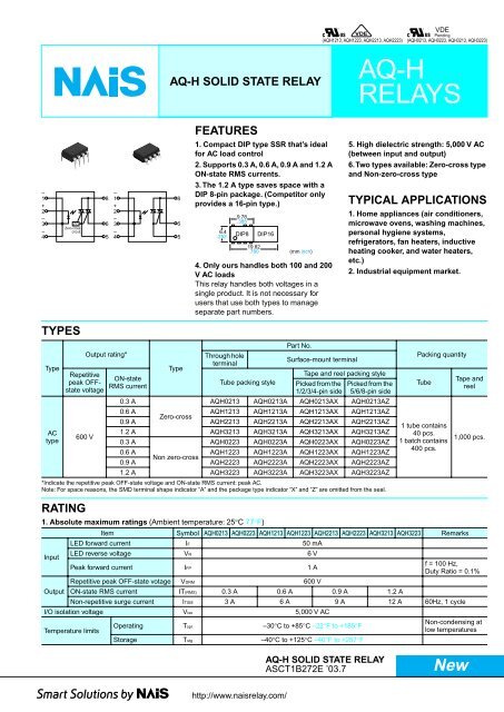
AQ-H SOLID STATE RELAY<br />
6<br />
5<br />
Type<br />
FEATURES<br />
1. Compact DIP type SSR that’s ideal<br />
for AC load control<br />
2. Supports 0.3 A, 0.6 A, 0.9 A and 1.2 A<br />
ON-state RMS currents.<br />
3. The 1.2 A type saves space with a<br />
DIP 8-pin package. (Competitor only<br />
provides a 16-pin type.)<br />
9.78<br />
.385<br />
6.4<br />
.252 DIP8 DIP16<br />
19.82<br />
.780<br />
4. Only ours handles both 100 and 200<br />
V AC loads<br />
This relay handles both voltages in a<br />
single product. It is not necessary for<br />
users that use both types to manage<br />
separate part numbers.<br />
Through hole<br />
terminal<br />
Tube packing style<br />
http://www.naisrelay.com/<br />
(mm inch)<br />
Part No.<br />
*Indicate the repetitive peak OFF-state voltage and ON-state RMS current: peak AC.<br />
Note: For space reasons, the SMD terminal shape indicator “A” and the package type indicator “X” and “Z” are omitted from the seal.<br />
RATING<br />
VDE<br />
VDE<br />
Pending<br />
(AQH1213, AQH1223, AQH2213, AQH2223) (AQH0213, AQH0223, AQH3213, AQH3223)<br />
Surface-mount terminal<br />
Tape and reel packing style<br />
Picked from the<br />
1/2/3/4-pin side<br />
AQ-H SOLID STATE RELAY<br />
ASCT1B272E ’03.7<br />
AQ-H<br />
RELAYS<br />
5. High dielectric strength: 5,000 V AC<br />
(between input and output)<br />
6. Two types available: Zero-cross type<br />
and Non-zero-cross type<br />
TYPICAL APPLICATIONS<br />
1. Home appliances (air conditioners,<br />
microwave ovens, washing machines,<br />
personal hygiene systems,<br />
refrigerators, fan heaters, inductive<br />
heating cooker, and water heaters,<br />
etc.)<br />
2. Industrial equipment market.<br />
Picked from the<br />
5/6/8-pin side<br />
0.3 A<br />
AQH0213 AQH0213A AQH0213AX AQH0213AZ<br />
0.6 A<br />
0.9 A<br />
Zero-cross<br />
AQH1213<br />
AQH2213<br />
AQH1213A<br />
AQH2213A<br />
AQH1213AX<br />
AQH2213AX<br />
AQH1213AZ<br />
AQH2213AZ<br />
1.2 A AQH3213 AQH3213A AQH3213AX AQH3213AZ<br />
0.3 A<br />
AQH0223 AQH0223A AQH0223AX AQH0223AZ<br />
0.6 A<br />
0.9 A<br />
Non zero-cross<br />
AQH1223<br />
AQH2223<br />
AQH1223A<br />
AQH2223A<br />
AQH1223AX<br />
AQH2223AX<br />
AQH1223AZ<br />
AQH2223AZ<br />
1.2 A AQH3223 AQH3223A AQH3223AX AQH3223AZ<br />
1. Absolute maximum ratings (Ambient temperature: 25°C 77°F)<br />
Input<br />
Output<br />
Packing quantity<br />
Tube<br />
1 tube contains<br />
40 pcs.<br />
1 batch contains<br />
400 pcs.<br />
Item Symbol AQH0213 AQH0223 AQH1213 AQH1223 AQH2213 AQH2223 AQH3213 AQH3223 Remarks<br />
LED forward current IF 50 mA<br />
LED reverse voltage VR 6 V<br />
Peak forward current IFP 1 A<br />
Repetitive peak OFF-state votage VDRM 600 V<br />
ON-state RMS current IT(RMS) 0.3 A 0.6 A 0.9 A 1.2 A<br />
<strong>New</strong><br />
Tape and<br />
reel<br />
1,000 pcs.<br />
f = 100 Hz,<br />
Duty Ratio = 0.1%<br />
Non-repetitive surge current ITSM 3 A 6 A 9 A 12 A 60Hz, 1 cycle<br />
I/O isolation voltage Viso 5,000 V AC<br />
Temperature limits<br />
Operating Topr –30°C to +85°C –22°F to +185°F<br />
Storage Tstg –40°C to +125°C –40°F to +257°F<br />
Non-condensing at<br />
low temperatures<br />
1
AQ-H<br />
2. Electrical characteristics (Ambient temperature: 25°C 77°F)<br />
Notes: *Recommended LED current IFT: 20 mA<br />
**Applicable part No.: AQH0213, AQH1213, AQH2213 and AQH3213.<br />
***Turn on time<br />
2<br />
Input<br />
Output<br />
Transfer<br />
characteristics<br />
Item Symbol AQH0213 AQH1213 AQH2213 AQH3213 AQH0223 AQH1223 AQH2223 AQH3223 Condition<br />
LED dropout voltage<br />
LED reverse current<br />
Peak OFF-state<br />
current<br />
Peak ON-state<br />
voltage<br />
Holding current<br />
Critical rate of rise of<br />
OFF-state voltage<br />
Typical<br />
VF<br />
1.18 V<br />
Maximum 1.3 V<br />
Typical<br />
IR<br />
Maximum 10 μA<br />
—<br />
IF = 10 mA<br />
VR = 6 V<br />
Typical<br />
— IF = 0 mA<br />
IDRM<br />
Maximum 100 μA<br />
VDRM = 600 V<br />
Typical<br />
— IF = 10 mA<br />
VTM<br />
Maximum 2.5 V<br />
ITM = Max.<br />
Typical<br />
—<br />
IH<br />
Maximum 25 mA<br />
Minimum dv/dt 200 V/μs VDRM = 600 V ×1/M2<br />
Trigger LED current* Maximum IFT 10 mA<br />
VD = 6 V<br />
RL = 100 Ω<br />
Zero-cross voltage** Maximum VZC 50 V — IF = 10 mA<br />
Turn on time*** Maximum TON 10 μs<br />
I/O isolation<br />
resistance<br />
DIMENSIONS<br />
6.4<br />
.252<br />
3.9±0.2<br />
.154±.008<br />
3.0<br />
.118<br />
Through hole terminal type<br />
9.78<br />
.385<br />
1.2<br />
.047<br />
2.54 2.54<br />
.100 .100<br />
1.2<br />
.047<br />
2.54<br />
0.5<br />
.020<br />
0.5<br />
0.5 .020<br />
.020 1.2<br />
1.2 .047<br />
.047<br />
.100<br />
0.5<br />
.020<br />
IF = 20 mA<br />
VD = 6 V<br />
RL = 100 Ω<br />
Minimum Riso 50 GΩ 500 V DC<br />
7.62<br />
.300<br />
3.4<br />
.134<br />
Input<br />
Output<br />
MAX. 10°<br />
MAX. 10°<br />
Terminal thickness: 0.25 .010<br />
General tolerance: ±0.1 ±.004<br />
Ton<br />
90%<br />
Surface mount terminal type<br />
6.4<br />
.252<br />
9.78<br />
.385<br />
7.62<br />
.300<br />
3.4<br />
.134<br />
0.2 +0.2<br />
–0<br />
.008 +.008<br />
–0<br />
1.2<br />
.047 1.2<br />
.047<br />
2.54 2.54<br />
.100 .100 2.54<br />
0.5<br />
0.5 .020 0.5 0.5<br />
.020 .020<br />
1.2<br />
.020<br />
.047 1.2<br />
.047<br />
.100<br />
MAX.10°<br />
3.4<br />
.134<br />
Terminal thickness: 0.25 .010<br />
General tolerance: ±0.1 ±.004<br />
1<br />
8-0.8 dia. hole<br />
8-.031 dia. hole<br />
PC board pattern<br />
(BOTTOM VIEW)<br />
6.4<br />
.252<br />
7.62<br />
.300<br />
2.54<br />
.100<br />
mm inch<br />
7.62<br />
2.54 .300<br />
.100<br />
Tolerance: ±0.1 ±.004<br />
Recommended mounting pad<br />
(TOP VIEW)<br />
8.3<br />
.327 1.9<br />
.075<br />
1.5<br />
.059<br />
2.54<br />
.100 2.54<br />
.100 2.54<br />
.100<br />
Tolerance: ±0.1 ±.004
SCHEMATIC AND WIRING DIAGRAMS<br />
Notes: E1: Power source at input side; IF: Trigger LED forward current; VL: Load voltage; IL: Load current;<br />
REFERENCE DATA<br />
1. ON-state RMS current vs. Ambient<br />
temperature characteristics<br />
Allowable ambient temperature:<br />
–30°C to +85°C –22°F to +185°F<br />
1.5<br />
ON-state RMS current, mA<br />
AQH3213, AQH3223<br />
1.2<br />
AQH2213, AQH2223<br />
0.9<br />
AQH1213, AQH1223<br />
0.6<br />
AQH0213, AQH0223<br />
0.3<br />
0<br />
–30 –20 0 20 40 60 8085 100<br />
Ambient temperature, °C<br />
4. LED dropout voltage vs. Ambient<br />
temperature characteristics<br />
LED current: 10 to 50 mA<br />
LED dropout voltage, V<br />
1.5<br />
1.4<br />
1.3<br />
1.2<br />
1.1<br />
1<br />
–40 –30 –20<br />
0 20 40 60 80 85<br />
Ambient temperature, °C<br />
7. Hold current vs. Ambient temperature<br />
characteristics<br />
Hold current, mA<br />
25<br />
20<br />
15<br />
10<br />
Schematic Output configuration Load Wiring diagram<br />
–<br />
1 8<br />
+<br />
2<br />
–<br />
3<br />
–<br />
4<br />
5<br />
ZC<br />
Zero-cross<br />
circuit<br />
–<br />
1 8<br />
+<br />
2<br />
–<br />
3<br />
6<br />
–<br />
4<br />
5<br />
AQH1213, AQH1223<br />
AQH0213, AQH0223<br />
AQH3213, AQH3223<br />
6<br />
5<br />
AQH2213, AQH2223<br />
0<br />
–40 –30–20 0 20 40 60 80 85<br />
Ambient temperature, °C<br />
1a AC<br />
50mA<br />
30mA<br />
20mA<br />
10mA<br />
2. On voltage vs. Ambient temperature<br />
characteristics<br />
LED current: 10 mA; ON current: Max.<br />
Measured portion: between terminals 6 and 8<br />
1.6<br />
On voltage, V<br />
1.4<br />
1.2<br />
1<br />
0.8<br />
AQH0213, AQH0223<br />
AQH1213, AQH1223<br />
AQH2213, AQH2223<br />
AQH3213, AQH3223<br />
0.6<br />
–40 –30–20 0 20 40 60 80 85<br />
Ambient temperature, °C<br />
5. Turn on time vs. LED current characteristics<br />
Load voltage: 6 V DC; Load resistance: 100Ω<br />
Measured portion: between terminals 6 and 8<br />
Turn on time, µs<br />
100<br />
80<br />
60<br />
40<br />
20<br />
0<br />
0 10 20 30 40 50<br />
LED current, mA<br />
8. Zero-cross voltage vs. Ambient temperature<br />
characteristics<br />
LED current: 10 mA<br />
50<br />
Zero-cross voltage, V<br />
40<br />
30<br />
20<br />
10<br />
AQH0213, AQH1213,<br />
AQH2213, AQH3213<br />
0<br />
–40 –30–20 0 20 40 60 80 85<br />
IF<br />
1<br />
2<br />
E1 IL<br />
VL (AC) IL<br />
3<br />
4<br />
1<br />
2<br />
Ambient temperature, °C<br />
8<br />
6<br />
5<br />
8<br />
Load<br />
Load<br />
AQ-H<br />
3. Trigger LED current vs. Ambient temperature<br />
characteristics<br />
Load voltage: 6 V DC;<br />
Load resistance: 100Ω<br />
10<br />
Trigger LED current, mA<br />
8<br />
6<br />
4<br />
2<br />
0<br />
–40 –30 –20<br />
0 20 40 60 80 85<br />
Ambient temperature, °C<br />
6. Repetitive peak OFF-state current vs. Load<br />
voltage characteristics<br />
LED current: 0 mA; Measured portion: between<br />
terminals 6 and 8; Ambient temperature: 25°C 77°F<br />
Repetitive peak OFF-state current, A<br />
10 –3<br />
10 –4<br />
10 –5<br />
10 –6<br />
10 –7<br />
10 –8<br />
10 –9<br />
Load<br />
E1 IL<br />
VL (AC) IL<br />
IF 3<br />
6<br />
Load<br />
4<br />
5<br />
10<br />
0 20 40 60 80 100<br />
–10<br />
Load voltage, V<br />
VL (AC)<br />
VL (AC)<br />
3
AQ-H<br />
CAUTIONS FOR USE<br />
1. For cautions regarding use, please<br />
refer to ’03-’04 Solid State Relays<br />
catalog.<br />
2. The internal IC could be damaged if<br />
a short forms between the I/O<br />
terminals while the solid state relay is<br />
powered.<br />
3. Output spike voltages<br />
1) The figure below shows an ordinary<br />
circuit. Please add a snubber circuit or<br />
varistor, as noise/surge on the load side<br />
could damage the unit or cause<br />
malfunctions.<br />
8. The following shows the packaging format<br />
1) Tape and reel<br />
4<br />
1 8<br />
2<br />
3<br />
4<br />
Type Tape dimensions Dimensions of paper tape reel<br />
8-pin SMD type<br />
6<br />
5<br />
Note) Connection of an external resister, etc.,<br />
to terminal No. 5 (gate) is not necessary.<br />
2) Even if spike voltages generated at the<br />
load are limited with a clamp diode if the<br />
circuit wires are long, spike voltages will<br />
occur by inductance. Keep wires as short<br />
as possible to minimize inductance.<br />
4. Ripple in the input power supply<br />
1) For LED operate current at Emin,<br />
maintain min. 10 mA<br />
2) Keep the LED operate current at 50 mA<br />
or less at Emax.<br />
Emin. Emax.<br />
4.5±0.3<br />
.177±.012<br />
Load<br />
0.3±0.05<br />
.012±.002<br />
VL(AC)<br />
5. When soldering terminals, keep<br />
soldering time to within 10s at 260°C<br />
500°F<br />
Device mounted<br />
on tape<br />
Tractor feed holes<br />
+0.1<br />
1.5 –0 dia.<br />
+.004<br />
.059 –0 dia.<br />
6. Cleaning<br />
The solid state relay forms an optical path<br />
by coupling a light-emitting diode (LED)<br />
and photodiode via transparent silicon<br />
resin.<br />
For this reason, avoid ultrasonic cleansing<br />
if at all possible.<br />
We recommend cleaning with an organic<br />
solvent. If you cannot avoid using<br />
ultrasonic cleansing, please ensure that<br />
the following conditions are met, and<br />
check beforehand for defects.<br />
• Frequency: 27 to 29 kHz<br />
• Ultrasonic output: No greater than 0.25<br />
W/cm 2<br />
• Cleaning time: No longer than 30<br />
seconds<br />
• Cleanser used: Asahiklin AK-225<br />
• Other: Submerge in solvent in order to<br />
prevent the PCB and elements from being<br />
contacted directly by the ultrasonic<br />
vibrations.<br />
Note: Applies to unit area ultrasonic output for<br />
ultrasonic baths.<br />
7. Soldering<br />
1) When soldering PC board terminals,<br />
keep soldering time to within 10 s at<br />
260°C 500°F.<br />
2) When soldering surface-mount<br />
terminals, the following conditions are<br />
recommended.<br />
(1) IR (Infrared reflow) soldering method<br />
Direction of picking<br />
4±0.1<br />
.157±.004<br />
12±0.1<br />
.472±.004<br />
10.1±0.1<br />
.400±.004<br />
2±0.1<br />
.079±.004<br />
1.75±0.1<br />
.069±.004<br />
7.5±0.1<br />
.295±.004<br />
16±0.3<br />
.630±.012<br />
10.2±0.1<br />
.402±.004<br />
1.55±0.1 dia.<br />
.061±.004 dia.<br />
(1) When picked from 1/2/3/4-pin side: Part No. AQH❍❍❍❍AX (Shown above)<br />
(2) When picked from 5/6/8-pin side: Part No. AQH❍❍❍❍AZ<br />
T3<br />
T2<br />
T1<br />
t1 t2<br />
T1 = 155 to 165°C 311 to 329°F<br />
T2 = 180°C 200°C 356 to 392°F<br />
T3 = 245°C 473°F or less<br />
t1 = 120 s or less<br />
t2 = 30 s or less<br />
2±0.5<br />
.079±.020<br />
(2) Vapor phase soldering method<br />
T2<br />
T1<br />
(3) Double wave soldering method<br />
T2<br />
T1<br />
t1 t2<br />
T1 = 180 to 200°C 366 to 392°F<br />
T2 = 215°C 419°F or less<br />
t1 = 40 s<br />
t2 = 90 s or less (40 s: SOP type)<br />
(4) Soldering iron method<br />
Tip temperature: 280 to 300°C 536 to<br />
572°F<br />
Wattage: 30 to 60 W<br />
Soldering time: within 5 seconds<br />
(5) Others<br />
Check mounting conditions before using<br />
other soldering methods (hot-air, hot<br />
plate, pulse heater, etc.)<br />
• The temperature profile indicates the<br />
temperature of the soldered terminal on<br />
the surface of the PC board. The ambient<br />
temperature may increase excessively.<br />
Check the temperature under mounting<br />
conditions.<br />
• The conditions for the infrared reflow<br />
soldering apply when preheating using<br />
the VPS method.<br />
21±0.8<br />
.827±.031<br />
80±1 dia.<br />
3.150±.039 dia.<br />
13±0.5 dia.<br />
.512±.020 dia.<br />
t1 t2 t3<br />
T1 = 155 to 165°C 311 to 329°F<br />
T2 = 260°C 500°F or less<br />
t1 = 60 s or less<br />
t2+t3 = 5 s or less<br />
17.5±2.0<br />
.689±.079<br />
2±0.5<br />
.079±.020<br />
mm inch<br />
300±2 dia.<br />
11.811±.079 dia.<br />
80±1 dia.<br />
3.150±.039 dia.
2) Tube<br />
Devices are packaged in a tube so pin No.<br />
1 is on the stopper B side. Observe<br />
correct orientation when mounting them<br />
on PC boards.<br />
(DIP type)<br />
StopperB StopperA<br />
9. Transportation and storage<br />
1) Extreme vibration during transport will<br />
warp the lead or damage the relay.<br />
Handle the outer and inner boxes with<br />
care.<br />
2) Storage under extreme conditions will<br />
cause soldering degradation, external<br />
appearance defects, and deterioration of<br />
the characteristics. The following storage<br />
conditions are recommended:<br />
• Temperature: 0 to 45°C 32 to 113°F<br />
• Humidity: Less than 70% R.H.<br />
• Atomosphere: No harmful gasses such<br />
as sulfurous acid gas, minimal dust.<br />
AQ-H<br />
5
AQ-H<br />
Internet Homepage<br />
North America<br />
Europe<br />
Please contact ..........<br />
6ARCT1B272E 200307-3YT<br />
: http://www.aromat.com/<br />
: http://www.mew-europe.com/<br />
These materials are printed on ECF pulp.<br />
These materials are printed with earth-friendly vegetable-based (soybean oil) ink.<br />
Asia & others : http://www.nais-e.com/<br />
• (Japanese) : http://www.mac-j.co.jp/<br />
• (Chinese) : http://www.cmew.com.cn/<br />
Matsushita Electric Works, Ltd.<br />
Automation Controls Company<br />
Head Office: 1048, Kadoma, Kadoma-shi, Osaka 571-8686, Japan<br />
Telephone: Japan (81) Osaka (06) 6908-1050<br />
Facsimile: Japan (81) Osaka (06) 6908-5781<br />
http://www.nais-e.com/<br />
COPYRIGHT © 2003 All Rights Reserved<br />
Specifications are subject to change without notice. Printed in Japan.