Speed Correction Drives For Shaft Phasing and Narrow - Zycon
Speed Correction Drives For Shaft Phasing and Narrow - Zycon
Speed Correction Drives For Shaft Phasing and Narrow - Zycon

You also want an ePaper? Increase the reach of your titles
YUMPU automatically turns print PDFs into web optimized ePapers that Google loves.
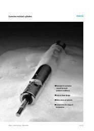
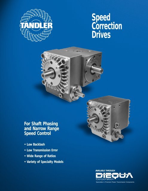
<strong>For</strong> <strong>Shaft</strong> <strong>Phasing</strong><br />
<strong>and</strong> <strong>Narrow</strong> Range<br />
<strong>Speed</strong> Control<br />
• Low Backlash<br />
• Low Transmission Error<br />
• Wide Range of Ratios<br />
• Variety of Specialty Models<br />
<strong>Speed</strong><br />
<strong>Correction</strong><br />
<strong>Drives</strong><br />
AVAILABLE THROUGH<br />
Specialists in Precision Power Transmission Components
DIEQUA CORPORATION<br />
2<br />
T<strong>and</strong>ler, the world leader in precision shaft phaseable gearbox manufacturing, has<br />
been satisfying the most dem<strong>and</strong>ing gearing requirements for over 50 years. In<br />
cooperation with DieQua Corporation, we are providing the most extensive <strong>and</strong><br />
highest quality speed correction drive program available. With the lowest backlash,<br />
the lowest transmission error, <strong>and</strong> the widest range of ratios <strong>and</strong> specialty models, you<br />
can be assured of maximum design versatility <strong>and</strong> superior performance.<br />
Contents<br />
Overview . . . . . . . . . . . . . . . . . . . . . . . . . . . . . . . . . . . . . . . . . . . . . .3<br />
Sizing Information . . . . . . . . . . . . . . . . . . . . . . . . . . . . . . . . . . . . .4 - 5<br />
SP2 Right Angle . . . . . . . . . . . . . . . . . . . . . . . . . . . . . . . . . . . . . .6 - 11<br />
PE2 Inline 3:1 . . . . . . . . . . . . . . . . . . . . . . . . . . . . . . . . . . . . . . .12 - 15<br />
PD2 Inline 1:1 . . . . . . . . . . . . . . . . . . . . . . . . . . . . . . . . . . . . . .16 - 19<br />
KD Inline 2:1 . . . . . . . . . . . . . . . . . . . . . . . . . . . . . . . . . . . . . . .20 - 23<br />
KD2 Inline 2:1 . . . . . . . . . . . . . . . . . . . . . . . . . . . . . . . . . . . . . .24 - 27<br />
Technical Data . . . . . . . . . . . . . . . . . . . . . . . . . . . . . . . . . . . . . .28 - 30<br />
Special Designs <strong>and</strong> Options . . . . . . . . . . . . . . . . . . . . . . . . . . . . . . . . .31
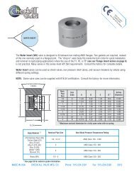
<strong>Speed</strong> <strong>Correction</strong> Gearboxes<br />
Unmatched Design Flexibility for controlling speed <strong>and</strong> position<br />
<strong>Speed</strong> correction gearboxes allow changes in the angular position of the output shaft<br />
relative to the input shaft, <strong>and</strong> provide the capability to vary the output speed within<br />
a narrow range. Through the integration of a secondary input shaft, extremely precise<br />
positioning <strong>and</strong> speed control can be easily achieved.<br />
SP2 with st<strong>and</strong>ard right angle SP2 with hollow shaft SP2 with reinforced shaft<br />
SP2 with switch SP2 with<br />
one-way auxiliary<br />
PE2 Single<br />
planetary in-line<br />
PD2 Double<br />
planetary in-line<br />
SP2 with<br />
two-way auxiliary<br />
KD Differential<br />
KD2 Differential<br />
TANDLER<br />
SPEED CORRECTION GEARBOXES 3
4<br />
SIZING<br />
SIZING SPEED CORRECTION GEARBOXES<br />
Sizing <strong>Speed</strong> <strong>Correction</strong> Gearboxes<br />
Pertinent Data<br />
1. Input speed.<br />
2. Gear ratio.<br />
3. Horsepower requirement.<br />
4. Method of shaft connection.<br />
5. Mounting position.<br />
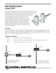
Explanation of Symbols<br />
To select any gearbox, use the appropriate charts<br />
<strong>and</strong> tables in this catalog. All of them use the<br />
following symbols:<br />
nin = input rpm<br />
nout = output rpm<br />
n1 = rpm on d1<br />
n2 = rpm on d2<br />
i = gear ratio = nin :nout<br />
itot<br />
= d1 :d2<br />
d = a shaft or a pinion<br />
Hp = horsepower<br />
M = torque<br />
Mdin = input torque, in Newton-meters, Nm<br />
Mdout = output torque, in Newton-meters, Nm<br />
Nm = Newton-meters<br />
N1 = input power, in kilowatts, kW<br />
N2 = output power, in kilowatts, kW<br />
C = operational factor<br />
All T<strong>and</strong>ler gearboxes are delivered with the appropriate<br />
quantity <strong>and</strong> type of oil for normal operation. <strong>For</strong> special<br />
lubrication <strong>and</strong> mounting requirements, consult the<br />
Technical Data section, page 28.<br />
<strong>Correction</strong> <strong>Shaft</strong> d 3<br />
<strong>Shaft</strong> d 2<br />
Pinion d 1
Steps for Gearbox Selection<br />
1. Calculate input torque. Input torque is defined as the torque<br />
entering the gearbox or driving torque, regardless if it is on the<br />
d1 pinion or the d2 shaft.<br />
Md in = 7160 x Hp<br />
nin 2. Find the appropriate sizing chart for your gear ratio on<br />
pages 6, 7, 12, 16, 20 or 24.<br />
3.Find input torque on the vertical axis <strong>and</strong> input rpm on the<br />
horizontal axis. The point of intersection will fall in a range that<br />
identifies the size gearbox you need.<br />
4. If your selection approaches the torque capacity of the<br />
gearbox, or if it is subject to extreme conditions, consult the<br />
operational factor chart on page 28.<br />
5. T<strong>and</strong>ler’s gear boxes are designed to operate without special<br />
cooling at temperatures up to 90°C (200°F). If your application<br />
approaches the maximum speed of the gearbox, or is subject to<br />
high ambient temperatures, consult your DieQua representative<br />
for special cooling options.<br />
6. Select the appropriate internal gear arrangement which<br />
specifies shaft rotations <strong>and</strong> correct shaft position.<br />
7. Consider how the gearbox is mounted...<br />
• If connecting with rigid or flexible couplings,<br />
consider alignment requirements.<br />
Consult your DieQua representative.<br />
• If connecting with a pulley or gear,<br />
check the radial load capacity for each shaft.<br />
Consult your DieQua representative.<br />
• If any shafts are mounted vertically, consider<br />
special bearing lubrication options.<br />
Consult your DieQua representative.<br />
8. Specify the T<strong>and</strong>ler part number.<br />
(See example below).<br />
Specifying the T<strong>and</strong>ler Part Number<br />
Type/Series<br />
Size of Gearboxes<br />
Total Ratio i tot = n 1 : n 2<br />
Gear Arrangement<br />
Special Option/Design<br />
SP2 A1 1:2 IIIR<br />
Note: When ordering, total ratio must be specified as i tot = d 1 :d 2<br />
Actual operational usage <strong>and</strong> ratio specification may be reversed.<br />
SIZING<br />
SIZING SPEED CORRECTION GEARBOXES 5
SP2 GEARBOXES<br />
6<br />
SP2<br />
St<strong>and</strong>ard Right Angle<br />
Type SP2 <strong>Speed</strong> <strong>Correction</strong> Gearbox<br />
This design combines a planetary gear system with a<br />
right angle spiral bevel gearbox. The result is<br />
unparalleled design flexibility. The SP2 gearbox is<br />
available in 7 st<strong>and</strong>ard sizes <strong>and</strong> 8 st<strong>and</strong>ard ratios.<br />
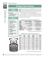
Sizing Charts for Driving on <strong>Shaft</strong> d 2<br />
Gear Ratio d 2:d 1 of 1:1<br />
*1Nm = 8.85 in. lbs.<br />
Available Ratios<br />
Type SP2 gearbox is available,<br />
for applications driving on pinion d1,<br />
i = d1/d2 = n1/n2, in 8 ratios:<br />
1.66:1* 1:1.5<br />
1.33:1* 1:2<br />
1:1 1:3<br />
1:1.2* 1:3.75*<br />
<strong>and</strong> applications driving on shaft d2,<br />
i = d2/d1 = n2/n1, in 8 ratios:<br />
4.5:1* 1.5:1<br />
3.75:1* 1.2:1*<br />
3:1 1:1<br />
2:1 1:1.33*<br />
* Not available in SP2 00<br />
Gear Ratio d 2:d 1 of 1.2:1 <strong>and</strong> 1.5:1<br />
Selection note: Lines represent the maximum input torque capacity of each size.
Gear Ratio d 2:d 1 of 2:1<br />
Gear Ratio d 2:d 1 of 3:1<br />
Gear Ratio d 2:d 1 of 3.75:1 Gear Ratio d 2:d 1 of 4.5:1<br />
*1Nm = 8.85 in. lbs.<br />
SP2<br />
SP2 GEARBOXES 7
SP2 GEARBOXES<br />
8<br />
SP2<br />
Size<br />
SP2 00<br />
SP2 01<br />
SP2 0A<br />
SP2 A1<br />
SP2 AB<br />
SP2 B1<br />
SP2 BC<br />
SP2 C1<br />
SP2 CD<br />
SP2 D1<br />
SP2 DE<br />
SP2 E1<br />
Schematic:<br />
Dimensions<br />
a �<br />
b c ø j7 dø 1j6 dø 2j6 dø 3j6 e�<br />
1)<br />
f g1 g2 h k1 k 2 k 3 l 1 l 2 l 3 m 1 m 2 m 3 m 4 m 5 n ø j7 oø j7<br />
r s t u�<br />
v w x y z<br />
80 110 74 16 20 12 60 3.5 70 32 105 M 6 M 6 M 6 25 35 20 135 93.5 65.5 55.5 77 80 48 M 6 48 79.5 100 40 80 80 80 0<br />
110 145 102 22 22 14 82 3.5 80 35 133 M 8 M 8 M 8 35 35 30 174 111 85 69 100 116 55 M 8 55 98 125 50 100 100 100 0<br />
110 145 102 22 22 14 82 3.5 80 40 148 M 8 M 8 M 8 35 35 30 189 111 89 81.75 106 130 60 M 8 60 112 150 55 110 110 110 26<br />
140 175 130 32 32 14 105 4.5 80 40 163 M10 M 8 M 8 45 45 30 214 137 104 81.75 106 130 60 M10 60 112 150 55 110 110 110 26<br />
140 175 130 32 32 14 105 4.5 80 40 171 M10 M10 M 8 45 45 30 222 137 108 93 94 155 60 M10 60 124 170 65 118 145 145 28<br />
170 215 160 42 42 14 130 4.5 80 40 186 M12 M10 M 8 60 60 30 252 172 123 93 94 155 60 M12 60 124 170 65 118 145 145 28<br />
170 215 160 42 42 18 130 4.5 95 45 194 M12 M10 M 8 60 60 30 261 172 125 112.75 105 185 70 M12 70 148 210 70 140 160 160 32<br />
210 260 195 55 55 18 160 5 95 45 214 M16 M10 M 8 85 85 30 306 220 145 112.75 105 185 70 M16 70 148 210 70 140 160 160 32<br />
210 260 195 55 55 26 160 5 140 60 233 M16 M10 M 8 85 85 45 326 220 153 132.5 150 225 85 M16 85 175 260 110 220 140 140 44.5<br />
260 330 245 60 60 26 200 5 140 60 258 M16 M10 M 8 95 95 45 361 265 178 132.5 150 225 85 M16 85 175 260 110 220 140 140 44.5<br />
260 330 245 60 60 32 200 5 180 60 269 M16 M12 M 8 95 95 45 373 265 182 165 172 290 90 M16 90 210 330 150 300 140 124 53<br />
330 430 310 65 75 32 260 5 180 60 304 M20 M12 M 8 100 120 45 413 340 217 165 172 290 90 M16/20 90 210 330 150 300 140 124 53<br />
Dimensions in mm<br />
1) Screwed-in length = k • 1.5<br />
Keys according to DIN 6885, Centering DIN 332<br />
Subject to changes.
Internal Gear Arrangements<br />
Key Dimensions<br />
Gearbox Size<br />
SP2 00<br />
SP2 01<br />
SP2 0A<br />
SP2 A1<br />
SP2 AB<br />
SP2 B1<br />
SP2 BC<br />
SP2 C1<br />
SP2 CD<br />
SP2 D1<br />
SP2 DE<br />
SP2 E1<br />
Keys according to DIN 6885, dimensions in mm<br />
Subject to changes.<br />
Ordering Example<br />
d1 = d2<br />
5 x 5 (d 1)<br />
6 x 6 (d 2)<br />
6 x 6<br />
6 x 6<br />
10 x 8<br />
10 x 8<br />
12 x 8<br />
12 x 8<br />
16 x 10<br />
16 x 10<br />
18 x 11<br />
18 x 11<br />
18 x 11 (d 1)<br />
20 x 12 (d 2)<br />
SP2 A1 1:2 III-V<br />
Type Size Total Ratio Gear Arrangement Special Design (Optional)<br />
d3<br />
4 x 4<br />
5 x 5<br />
5 x 5<br />
5 x 5<br />
5 x 5<br />
5 x 5<br />
6 x 6<br />
6 x 6<br />
8 x 7<br />
8 x 7<br />
10 x 8<br />
10 x 8<br />
Backlash:<br />
St<strong>and</strong>ard 7 - 9 arc minutes<br />
Reduced 4 - 6 arc minutes<br />
Transmission Error:<br />
St<strong>and</strong>ard 6 - 8 arc minutes<br />
G2 4 - 6 arc minutes<br />
G1 2 - 3 arc minutes<br />
Note: Disengage <strong>and</strong><br />
Reversing models may add<br />
up to 1.5 times these values.<br />
SP2<br />
SP2 GEARBOXES 9
SP2 GEARBOXES<br />
10<br />
SP2<br />
Positional <strong>Correction</strong> Factors (phasing)<br />
1 revolution = 360° on worm shaft d 3 for drive on shaft d 1 corresponds to:<br />
<strong>For</strong> output shaft d2 (thru-shaft)<br />
1° 36' 2° 2° 40' 3° 12'<br />
Ratio of the overall drive (i = d1 : d2 )<br />
1.66:1 1.33:1 1:1 1:1.2<br />
<strong>For</strong> drive on the thru-shaft d2 , for all the above ratios, the differential movement on the shaft<br />
d1 = ± 2° 40' for one revolution of the worm shaft d3 .<br />
Note: Other correction rates are available.<br />
<strong>Speed</strong> <strong>Correction</strong> Factors for Worm <strong>Shaft</strong> d 3<br />
Other ratios available<br />
Power Requirements for Worm <strong>Shaft</strong> d 3<br />
To size the correction motor for shaft d3, use the following<br />
formula to determine the required input torque Md3, with<br />
main drive on shaft d2:<br />
Md3 = Output torque<br />
88<br />
To determine the horsepower requirement of the correction<br />
motor, use the following formula:<br />
Hp = Md3 x n3 (correction shaft speed)<br />
7160<br />
Note: When driving on shaft d1 for speed increasing<br />
applications, consult your DieQua representative for<br />
sizing instructions.<br />
4°<br />
1:1.5<br />
5° 20'<br />
1:2<br />
8°<br />
1:3<br />
10°<br />
1:3.75<br />
12°<br />
1:4.5
Operational Factors<br />
The sizing charts for SP2 gearboxes identify the<br />
torque carrying capacity for sizes SP2 00 through<br />
SP2 E1 gearboxes. These ratings were created by<br />
computations <strong>and</strong> verified by extensive test st<strong>and</strong><br />
operations. Maximum acceptable operating<br />
temperatures are 90ºC. To maintain proper<br />
lubrication, ISO VG 46 mineral based oils are<br />
used.<br />
Radial Load Capacities FR on <strong>Shaft</strong> d1<br />
Radial Load Capacities FR on <strong>Shaft</strong> d2<br />
Values are higher with taper bearing option.<br />
Note: <strong>For</strong> axial load capacities FA on shaft d1 or d2, consult your DieQua representative.<br />
1 N = .22 lbs.<br />
<strong>For</strong> applications of continuous high temperature<br />
operation, ISO VG 68 synthetic oils are used. If<br />
the design data indicates that maximum torque<br />
ratings may be reached, for any given size gearbox,<br />
operational factors need to be considered in the<br />
sizing calculations. See page 28 for more<br />
information, or consult your DieQua<br />
representative.<br />
Size<br />
SP2 00<br />
SP2 01<br />
SP2 A1<br />
SP2 B1<br />
SP2 C1<br />
SP2 D1<br />
SP2 E1<br />
Size<br />
SP2 00<br />
SP2 01<br />
SP2 A1<br />
SP2 B1<br />
SP2 C1<br />
SP2 D1<br />
SP2 E1<br />
@ Min. rpm<br />
2000 N<br />
3000 N<br />
5000 N<br />
6500 N<br />
7000 N<br />
10,000 N<br />
13,000 N<br />
@ Min. rpm<br />
600 N<br />
800 N<br />
3900 N<br />
4800 N<br />
5600 N<br />
8500 N<br />
10,900 N<br />
@ Max. rpm<br />
500 N<br />
800 N<br />
1000 N<br />
1400 N<br />
2780 N<br />
4590 N<br />
8200 N<br />
@ Max. rpm<br />
200 N<br />
400 N<br />
1700 N<br />
2200 N<br />
3000 N<br />
5600 N<br />
8300 N<br />
SP2<br />
SP2 GEARBOXES 11
SINGLE-PLANETARY<br />
12<br />
PE2<br />
Single-Planetary<br />
Type PE2 <strong>Speed</strong> <strong>Correction</strong> Gearbox<br />
The PE2 is a single stage planetary gearbox used<br />
for in-line shaft phasing or narrow range speed<br />
control. The unit is used as a 3:1 reducer or a 1:3<br />
increaser, depending on whether the d 1 or d 2 shaft<br />
is used as the input. This gearbox is available in 7<br />
st<strong>and</strong>ard sizes.<br />
Sizing Charts<br />
Input <strong>Speed</strong> on <strong>Shaft</strong> d 1<br />
*1Nm = 8.85 in. lbs.<br />
Available Ratios<br />
PE2 gearbox is available in 2 ratios:<br />
3:1 1:3<br />
Input <strong>Speed</strong> on <strong>Shaft</strong> d 2<br />
Selection note: Lines represent the maximum input torque capacity of each size.
Schematic:<br />
Dimensions<br />
Size<br />
PE2 00<br />
PE2 01<br />
PE2 A1<br />
PE2 B1<br />
PE2 C1<br />
PE2 D1<br />
PE2 E1<br />
u �<br />
b d ø 1j6 dø 2j6 dø 3j6 f g 1 g 2 l 1 l 2 l 3 m 1 m 2 m 4 m 5 n ø j7 o ø j7 s t v 1 w 1 y 1 z<br />
100 74.5 14 16 12 5 70 32 25 25 20 65 69.5 55.5 77 80 48 48 79.5 40 80 80 0<br />
125 87 16 22 14 6 80 35 30 35 30 75 89 69 100 116 55 55 98 50 100 100 0<br />
150 105 22 32 14 6 80 40 35 45 30 87 110 81.75 106 130 60 60 112 55 110 110 26<br />
170 117 32 42 14 6 80 40 45 60 30 105 129 93 94 155 60 60 124 65 118 145 28<br />
210 127 42 55 18 7 95 45 60 85 30 125 161 112.75 105 185 70 70 148 70 140 160 32<br />
260 150 50 60 26 8140 60 75 95 45 153 183 132.5 150 225 85 85 175 110 220 140 44.5<br />
330 164 60 65 32 9180 60 80 100 45 166 196 165 172 290 90 90 210 150 300 124 /140 53<br />
Dimensions in mm<br />
Keys according to DIN 6885, Centering DIN 332<br />
Subject to changes.<br />
Dimensions for Mounting Holes <strong>and</strong> Oil Sight-Glass<br />
Size<br />
PD2 <strong>and</strong><br />
PE2<br />
00<br />
01<br />
A1<br />
B1<br />
C1<br />
D1<br />
E1<br />
1)<br />
v2 w2 y2 x1 x2 k1 k 2 k 3<br />
33 60 80 29.5 30 M 5 M 6 M 6<br />
50 85 100 36 32 M 6 M 8 M 8<br />
55 95 110 40 42 M 8 M 8 M 8<br />
65 118 145 52 38 M10 M10 M 8<br />
70 140 160 50 46 M12 M10 M 8<br />
100 170 220 57 58 M12 M10 M 8<br />
125 220 290 63 60 M16 M12 M 8<br />
Dimensions in mm<br />
1) Screwed-in length = k • 1.5<br />
St<strong>and</strong>ard Sight Glass<br />
c j h<br />
68 50 44.5<br />
92 58 52<br />
112 72 61<br />
124 78 71<br />
145 112 76<br />
185 110 90<br />
235 140 106<br />
Optional Sight Glass<br />
c e = j h<br />
--- --- ---<br />
92 76 52<br />
112 76 61<br />
123 76 71<br />
164 127 73<br />
192 127 90<br />
227 127 118<br />
r 1<br />
thread<br />
d 1<br />
key<br />
M 6 5 x 5<br />
M 6 5 x 5<br />
M 8 6 x 6<br />
M10 10 x 8<br />
M12 12 x 8<br />
M16 14 x 9<br />
M16 18 x 11<br />
r 2<br />
thread<br />
d 2<br />
key<br />
M 6 5 x 5<br />
M 8 6 x 6<br />
M10 10 x 8<br />
M12 12 x 8<br />
M16 16 x 10<br />
M16 18 x 11<br />
M16 18 x 11<br />
r 3<br />
thread<br />
d 3<br />
key<br />
M 5 4 x 4<br />
M 6 5 x 5<br />
M 6 5 x 5<br />
M 6 5 x 5<br />
M 6 6 x 6<br />
M 8 8 x 7<br />
M10 10 x 8<br />
PE2<br />
SINGLE-PLANETARY 13
SINGLE-PLANETARY<br />
14<br />
PE2<br />
Positional <strong>Correction</strong> Factors (phasing)<br />
One revolution of 360 degrees of the worm gear<br />
shaft equals 1/135 of a revolution (2 degrees 40<br />
minutes) in drive output on shaft d 2, or 1/45 of a<br />
revolution (8 degrees) in drive output on shaft d 1.<br />
<strong>Speed</strong> <strong>Correction</strong> Factors<br />
Power Requirements for Worm <strong>Shaft</strong> d 3<br />
To size the correction motor for shaft d3, use the following<br />
formula to determine the required input torque Md3, with<br />
main drive on shaft d1:<br />
Md3 = Output torque<br />
88<br />
To determine the horsepower requirement of the correction<br />
motor, use the following formula:<br />
Hp = Md3 x n3 (correction shaft speed)<br />
7160<br />
Note: When driving on shaft d2 for speed increasing<br />
applications, consult your DieQua representative for<br />
sizing instructions.<br />
Ordering Example<br />
PE2 A1 3:1<br />
Type Size Total Ratio Special Design (Optional)<br />
Note: Other correction rates are available.<br />
Backlash:<br />
St<strong>and</strong>ard 4 - 5 arc minutes<br />
Reduced 2 - 3 arc minutes<br />
Transmission Error:<br />
St<strong>and</strong>ard 5 - 7 arc minutes<br />
G2 4 - 5 arc minutes<br />
G1 2 - 3 arc minutes
Operational Factors<br />
The sizing charts for PE2 gearboxes identify the<br />
torque carrying capacity for sizes PE2 00 through<br />
PE2 E1 gearboxes. These ratings were created by<br />
computations <strong>and</strong> verified by extensive test st<strong>and</strong><br />
operations. Maximum acceptable operating<br />
temperatures are 90ºC. To maintain proper<br />
lubrication, ISO VG 46 mineral based oils are used.<br />
Radial Load Capacities FR on <strong>Shaft</strong> d 1<br />
Radial load capacities may be increased using different bearing types.<br />
Radial Load Capacities FR on <strong>Shaft</strong> d 2<br />
Note: <strong>For</strong> axial load capacities FA on shaft d1 or d2, consult your DieQua representative.<br />
1 N = .22 lbs.<br />
<strong>For</strong> applications of continuous high temperature<br />
operation, ISO VG 68 synthetic oils are used. If the<br />
design data indicates that maximum torque ratings<br />
may be reached, for any given size gearbox,<br />
operational factors need to be considered in the<br />
sizing calculations. See page 28 for more<br />
information, or consult your DieQua representative.<br />
Size<br />
PE2 00<br />
PE2 01<br />
PE2 A1<br />
PE2 B1<br />
PE2 C1<br />
PE2 D1<br />
PE2 E1<br />
Size<br />
PE2 00<br />
PE2 01<br />
PE2 A1<br />
PE2 B1<br />
PE2 C1<br />
PE2 D1<br />
PE2 E1<br />
@ Min. rpm<br />
1100 N<br />
1500 N<br />
2000 N<br />
3000 N<br />
4500 N<br />
5000 N<br />
7500 N<br />
@ Min. rpm<br />
2000 N<br />
3000 N<br />
5000 N<br />
6500 N<br />
7000 N<br />
10,000 N<br />
13,000 N<br />
@ Max. rpm<br />
250 N<br />
450 N<br />
500 N<br />
750 N<br />
1670 N<br />
2380 N<br />
4370 N<br />
@ Max. rpm<br />
500 N<br />
800 N<br />
1000 N<br />
1400 N<br />
2420 N<br />
4320 N<br />
7530 N<br />
PE2<br />
SINGLE PLANETARY 15
DOUBLE-PLANETARY<br />
16<br />
PD2<br />
Double-Planetary<br />
Type PD2 <strong>Speed</strong> <strong>Correction</strong> Gearbox<br />
The PD2 is a dual stage planetary gearbox used<br />
for in-line shaft phasing or narrow range speed<br />
control. The unit is offered in a 1:1 ratio <strong>and</strong> is<br />
available in 7 st<strong>and</strong>ard sizes.<br />
Sizing Chart<br />
Input <strong>Speed</strong> on <strong>Shaft</strong> d 1 or d 2<br />
*1Nm = 8.85 in. lbs.<br />
Available Ratios<br />
PD2 gearbox is available in1 ratio:<br />
1:1<br />
Selection note: Lines represent the maximum input torque capacity of each size.
Schematic:<br />
Dimensions<br />
Size<br />
PD2 00<br />
PD2 01<br />
PD2 A1<br />
PD2 B1<br />
PD2 C1<br />
PD2 D1<br />
PD2 E1<br />
u �<br />
b d 1 ø j6 d ø 2j6 dø 3j6 f g 1 g 2 l 1 l 2 l 3 m 1 m 2 m 4 m 5 n ø j7 o ø j7 p s t v 1 w 1 y 1 z<br />
100 130 16 16 12 5 70 32 25 25 20 120.5 69.5 55.5 77 80 48 39.5 48 79.5 40 80 80 0<br />
125 148 22 22 14 6 80 35 35 35 30 141 89 69 100 116 55 48 55 98 50 100 100 0<br />
150 171 32 32 14 6 80 40 45 45 30 163 110 81.75 106 130 60 59 60 112 55 110 110 26<br />
170 186 42 42 14 6 80 40 60 60 30 189 129 93 94 155 60 63 60 124 65 118 145 28<br />
210 212 55 55 18 7 95 45 85 85 30 235 161 112.75 105 185 70 69 70 148 70 140 160 32<br />
260 242 60 60 26 7 140 60 95 95 45 263 183 132.5 150 225 85 81 85 175 110 220 140 44.5<br />
330 276 65 65 32 9 180 60 100 100 45 298 196 165 172 290 90 87 90 210 150 300 140 53<br />
Dimensions in mm<br />
Keys according to DIN 6885, Centering DIN 332<br />
Subject to changes.<br />
Dimensions for Mounting Holes <strong>and</strong> Oil Sight-Glass<br />
Size<br />
PD2 <strong>and</strong><br />
PE2<br />
00<br />
01<br />
A1<br />
B1<br />
C1<br />
D1<br />
E1<br />
1)<br />
v2 w2 y2 x1 x2 k1 k 2 k 3<br />
33 60 80 29.5 30 M 5 M 6 M 6<br />
50 85 100 36 32 M 6 M 8 M 8<br />
55 95 110 40 42 M 8 M 8 M 8<br />
65 118 145 52 38 M10 M10 M 8<br />
70 140 160 50 46 M12 M10 M 8<br />
100 170 220 57 58 M12 M10 M 8<br />
125 220 290 63 60 M16 M12 M 8<br />
Dimensions in mm<br />
1) Screwed-in length = k • 1.5<br />
St<strong>and</strong>ard Sight Glass<br />
c j h<br />
68 50 44.5<br />
92 58 52<br />
112 72 61<br />
124 78 71<br />
145 112 76<br />
185 110 90<br />
235 140 106<br />
Optional Sight Glass<br />
c e = j h<br />
--- --- ---<br />
92 76 52<br />
112 76 61<br />
123 76 71<br />
164 127 73<br />
192 127 90<br />
227 127 118<br />
r 1 = r 2<br />
thread<br />
d 1 = d 2<br />
M 6 5 x 5<br />
M 8 6 x 6<br />
M10 10 x 8<br />
M12 12 x 8<br />
M16 16 x 10<br />
M16 18 x 11<br />
M16 18 x 11<br />
r 3<br />
thread<br />
d 3<br />
M 5 4 x 4<br />
M 6 5 x 5<br />
M 6 5 x 5<br />
M 6 5 x 5<br />
M 6 6 x 6<br />
M 8 8 x 7<br />
M10 10 x 8<br />
PD2<br />
DOUBLE-PLANETARY 17
DOUBLE-PLANETARY<br />
18<br />
PD2<br />
Positional <strong>Correction</strong> Factors (phasing)<br />
One revolution of 360 degrees of the worm gear<br />
shaft equals 1/135 of a revolution (2 degrees 40<br />
minutes) on shafts d 1 or d 2.<br />
<strong>Speed</strong> <strong>Correction</strong> Factors<br />
Power Requirements for Worm <strong>Shaft</strong> d 3<br />
To size the correction motor for shaft d3, use the following<br />
formula to determine the required input torque Md3, with<br />
main drive on shaft d1:<br />
Md3 = Output torque<br />
88<br />
To determine the horsepower requirement of the correction<br />
motor, use the following formula:<br />
Hp = Md3 x n3 (correction shaft speed)<br />
7160<br />
Note: When driving on shaft d2, consult your DieQua<br />
representative for sizing instructions.<br />
Ordering Example<br />
PD2 A1 1:1<br />
Type Size Total Ratio Special Design (Optional)<br />
Note: Other correction rates are available.<br />
Backlash:<br />
St<strong>and</strong>ard 7 - 9 arc minutes<br />
Reduced 4 - 5 arc minutes<br />
Transmission Error:<br />
St<strong>and</strong>ard 6 - 8 arc minutes<br />
G2 5 - 6 arc minutes<br />
G1 2 - 3 arc minutes
Operational Factors<br />
The sizing charts for PD2 gearboxes identify<br />
the torque carrying capacity for sizes PD2 00<br />
through PD2 E1 gearboxes. These ratings were<br />
created by computations <strong>and</strong> verified by extensive<br />
test st<strong>and</strong> operations. Maximum acceptable<br />
operating temperatures are 90ºC. To maintain<br />
proper lubrication, ISO VG 46 mineral based oils<br />
are used.<br />
Radial Load Capacities FR on <strong>Shaft</strong> d 1 <strong>and</strong> <strong>Shaft</strong> d 2<br />
Note: <strong>For</strong> axial load capacities FA on shaft d1 or d2, consult your DieQua representative.<br />
1 N = .22 lbs.<br />
<strong>For</strong> applications of continuous high temperature<br />
operation, ISO VG 68 synthetic oils are used. If<br />
the design data indicates that maximum torque<br />
ratings may be reached, for any given size gearbox,<br />
operational factors need to be considered in the<br />
sizing calculations. See page 28 for more<br />
information, or consult your DieQua<br />
representative.<br />
Size @ Min. rpm<br />
PD2 00 2000 N<br />
PD2 01 3000 N<br />
PD2 A1 5000 N<br />
PD2 B1 6500 N<br />
PD2 C1 7000 N<br />
PD2 D1 10,000 N<br />
PD2 E1 13,000 N<br />
@ Max. rpm<br />
500 N<br />
800 N<br />
1000 N<br />
1400 N<br />
2780 N<br />
4590 N<br />
8200 N<br />
PD2<br />
DOUBLE-PLANETARY 19
DIFFERENTIAL<br />
20<br />
KD<br />
Differential KD<br />
Type KD <strong>Speed</strong> <strong>Correction</strong> Gearbox<br />
The KD gearbox is used for in-line shaft phasing or<br />
narrow range speed control. The unit is used as a 2:1<br />
reducer or 1:2 increaser, depending on whether the<br />
d1 or the d2 shaft is used as the input. This gearbox<br />
is available in 6 st<strong>and</strong>ard sizes.<br />
Sizing Charts<br />
Input <strong>Speed</strong> on <strong>Shaft</strong> d 1<br />
*1Nm = 8.85 in. lbs.<br />
Available Ratios<br />
KD gearbox is available in 2 ratios:<br />
1:2 2:1<br />
Input <strong>Speed</strong> on <strong>Shaft</strong> d 2
Schematic:<br />
Dimensions<br />
Size<br />
KD 01<br />
KD A1<br />
KD B1<br />
KD C1<br />
KD D1<br />
KD E1<br />
a �<br />
b c ø j7 d ø 1j6 d ø 2j6 d ø 3j6 e �<br />
f k 1)<br />
l 1 l 2 l 3 m 1 m 2 m 3 m 4 m 5 n p r 1 r 2 r 3 S j7<br />
110 145 102 14 18 10 82 3.5 M 8 30 35 20 106 111 82 29 37.5 61 50<br />
140 175 130 22 28 14 105 4.5 M10 35 45 30 127 137 107 38.5 48.5 79 61<br />
170 215 160 28 36 18 130 4.5 M12 45 55 30 157 167 122 49 60 95 77<br />
210 260 195 36 45 22 160 5 M16 55 60 35 190 195 147 58 74 115 95<br />
260 330 245 45 55 26 200 5 M16 70 85 45 240 255 184 74 88 143 110<br />
330 430 310 55 65 38 260 5 M20 85 100 65 305 320 241 100 113.5 180 150<br />
Dimensions in mm<br />
Keys according to DIN 6885, Centering DIN 332<br />
1) Screwed-in length = k • 1.5<br />
Subject to changes<br />
Key Dimensions<br />
Gearbox Size<br />
KD 01<br />
KD A1<br />
KD B1<br />
KD C1<br />
KD D1<br />
KD E1<br />
d1<br />
5 x 5 x 25<br />
6 x 6 x 30<br />
8 x 7 x 40<br />
10 x 8 x 50<br />
14 x 9 x 63<br />
16 x 10 x 70<br />
Keys according to DIN 6885, dimensions in mm<br />
Subject to changes.<br />
d2<br />
6 x 6 x 30<br />
8 x 7 x 40<br />
10 x 8 x 50<br />
14 x 9 x 50<br />
16 x 10 x 70<br />
18 x 11 x 90<br />
d3<br />
3 x 3 x 16<br />
5 x 5 x 25<br />
6 x 6 x 25<br />
6 x 6 x 30<br />
8 x 7 x 36<br />
10 x 8 x 56<br />
M 6 M 6 – 50<br />
M 8 M 8 M 5 56<br />
M 8 M10 M 6 62<br />
M10 M12 M 8 74<br />
M12 M16 M 8 83<br />
M16 M16 M10 103<br />
KD<br />
DIFFERENTIAL 21
DIFFERENTIAL<br />
22<br />
KD<br />
Positional <strong>Correction</strong> Factors (phasing)<br />
One revolution of 360 degrees of the worm shaft d 3<br />
equals 5 degrees in drive output on shaft d 2 or 10<br />
degrees in drive output on shaft d 1.<br />
<strong>Speed</strong> <strong>Correction</strong> Factors<br />
Power Requirements for Worm <strong>Shaft</strong> d 3<br />
To size the correction motor for shaft d3, use the following<br />
formula to determine the required input torque Md3, with<br />
main drive on shaft d1:<br />
Md 3 = Md 1<br />
23.50<br />
To determine the horsepower requirement of the correction<br />
motor, use the following formula:<br />
Hp = Md3 x n3 (correction shaft speed)<br />
7160<br />
Note: When driving on shaft d2, consult your DieQua<br />
representative for sizing instructions.<br />
Ordering Example<br />
KD A1 1:2<br />
Type Size Total Ratio Special Design (Optional)<br />
Note: Other correction rates are available.
Operational Factors<br />
The sizing charts for KD gearboxes identify the<br />
torque carrying capacity for sizes KD 01 through<br />
KD E1 gearboxes. These ratings were created by<br />
computations <strong>and</strong> verified by extensive test st<strong>and</strong><br />
operations. Maximum acceptable operating<br />
temperatures are 90ºC. To maintain proper<br />
lubrication, ISO VG 46 mineral based oils are used.<br />
Radial Load Capacities FR on <strong>Shaft</strong> d 1 <strong>and</strong> <strong>Shaft</strong> d 2<br />
Gearbox Size<br />
Radial Load Capacity on shaft d1 or shaft d2<br />
KD 01<br />
200 N<br />
KD A1<br />
300 N<br />
KD B1<br />
400 N<br />
KD C1<br />
550 N<br />
KD D1<br />
750 N<br />
KD E1<br />
1 N = .22 lbs.<br />
1000 N<br />
<strong>For</strong> higher radial capacities, use the KD2 series.<br />
Backlash:<br />
St<strong>and</strong>ard 5 - 7 arc minutes<br />
Reduced 3 - 4 arc minutes<br />
<strong>For</strong> applications of continuous high temperature<br />
operation, ISO VG 68 synthetic oils are used. If the<br />
design data indicates that maximum torque ratings<br />
may be reached, for any given size gearbox,<br />
operational factors need to be considered in the<br />
sizing calculations. See page 28 for more<br />
information, or consult your DieQua representative.<br />
Transmission Error:<br />
St<strong>and</strong>ard 6 - 8 arc minutes<br />
G2 5 - 6 arc minutes<br />
G1 2 - 3 arc minutes<br />
KD<br />
DIFFERENTIAL 23
DIFFERENTIAL<br />
24<br />
KD2<br />
Differential KD2<br />
Type KD2 <strong>Speed</strong> <strong>Correction</strong> Gearbox<br />
The KD2 model has a number of design advantages<br />
over the KD model. They include a higher<br />
correction ratio for more precise speed control, a<br />
self-locking worm gear, <strong>and</strong> a modified bearing<br />
configuration providing for higher radial load <strong>and</strong><br />
torque transmission capacities.<br />
Sizing Charts<br />
Input <strong>Speed</strong> on <strong>Shaft</strong> d1 *1Nm = 8.85 in. lbs.<br />
Available Ratios<br />
KD2 gearbox is available in 2 ratios:<br />
1:2 2:1<br />
This unit is also used as a 2:1 reducer or 1:2<br />
increaser, depending on whether the d 1 or the d 2<br />
shaft is used as the input. It is available in 5 st<strong>and</strong>ard<br />
sizes.<br />
Input <strong>Speed</strong> on <strong>Shaft</strong> d 2
Schematic:<br />
Dimensions<br />
Size<br />
KD2 A1<br />
KD2 B1<br />
KD2 C1<br />
KD2 D1<br />
KD2 E1<br />
a �<br />
b c ø j7 d ø 1j6 d ø 2j6 d ø 3j6 e �<br />
g h k 1)<br />
l 1 l 2 l 3 m 1 m 2 m 3 m 4 m 5 n ø o p r 1 r 2 r 3 S j7<br />
140 175 130 22 28 14 105 5.5 41.5 M10 35 45 30 164 174 107 38.5 48.5 79<br />
170 215 160 28 36 18 130 7.5 54.5 M12 45 55 30 207 217 122 49 60 95<br />
210 260 195 36 45 22 160 6 73 M16 55 60 35 258 263 147 58 74 115<br />
260 330 245 45 55 26 200 7 94 M16 70 85 45 329 344 184 74 88 143<br />
330 430 310 55 65 38 260 9 130 M20 85 100 65 430 445 241 100 113.5 180<br />
Dimensions in mm<br />
Keys according to DIN 6885, Centering DIN 332<br />
1) Screwed-in length = k • 1.5<br />
Subject to changes<br />
Key Dimensions<br />
Gearbox Size<br />
KD2 A1<br />
KD2 B1<br />
KD2 C1<br />
KD2 D1<br />
KD2 E1<br />
d1<br />
6 x 6 x 30<br />
8 x 7 x 40<br />
10 x 8 x 50<br />
14 x 9 x 63<br />
16 x 10 x 70<br />
Keys according to DIN 6885, dimensions in mm<br />
Subject to changes.<br />
d2<br />
8 x 7 x 40<br />
10 x 8 x 50<br />
14 x 9 x 50<br />
16 x 10 x 70<br />
18 x 11 x 90<br />
d3<br />
5 x 5 x 25<br />
6 x 6 x 25<br />
6 x 6 x 30<br />
8 x 7 x 36<br />
10 x 8 x 56<br />
90 61 M 8 M 8 M 5 56<br />
110 77 M 8 M10 M 6 62<br />
135 95 M10 M12 M 8 74<br />
150 110 M12 M16 M 8 83<br />
230 150 M16 M16 M10 103<br />
KD2<br />
DIFFERENTIAL 25
DIFFERENTIAL<br />
26<br />
KD2<br />
Positional <strong>Correction</strong> Factors (phasing)<br />
One revolution of 360 degrees of the worm shaft<br />
d 3 equals 3 degrees in drive output on shaft d 2 or 6<br />
degrees in drive output on shaft d 1.<br />
<strong>Speed</strong> <strong>Correction</strong> Factors<br />
Power Requirements for Worm <strong>Shaft</strong> d3<br />
To size the correction motor for shaft d3, use the following<br />
formula to determine the required input torque Md3, with<br />
main drive on shaft d1:<br />
Ordering Example<br />
Md 3 = Md 1<br />
39<br />
To determine the horsepower requirement of the correction<br />
motor, use the following formula:<br />
Hp = Md3 x n3 (correction shaft speed)<br />
7160<br />
Note: When driving on shaft d2 for speed increasing<br />
applications, consult your DieQua representative for<br />
sizing instructions.<br />
KD2 A1 1:2<br />
Type Size Total Ratio Special Design (Optional)<br />
Note: Other correction rates are available.
Operational Factors<br />
The sizing charts for KD2 gearboxes identify the<br />
torque carrying capacity for sizes KD2 A1 through<br />
KD2 E1 gearboxes. These ratings were created by<br />
computations <strong>and</strong> verified by extensive test st<strong>and</strong><br />
operations. Maximum acceptable operating<br />
temperatures are 90ºC. To maintain proper<br />
lubrication, ISO VG 46 mineral based oils are used.<br />
Radial Load Capacities FR on <strong>Shaft</strong> d1 <strong>and</strong> <strong>Shaft</strong> d2<br />
1 N = .22 lbs.<br />
Gearbox Size<br />
KD2 A1<br />
KD2 B1<br />
KD2 C1<br />
KD2 D1<br />
KD2 E1<br />
<strong>Shaft</strong> d1<br />
1250 N<br />
1700 N<br />
2400 N<br />
3000 N<br />
3500 N<br />
Backlash:<br />
St<strong>and</strong>ard 5 - 7 arc minutes<br />
Reduced 3 - 4 arc minutes<br />
<strong>Shaft</strong> d2<br />
1500 N<br />
2200 N<br />
3250 N<br />
3800 N<br />
4500 N<br />
<strong>For</strong> applications of continuous high temperature<br />
operation, ISO VG 68 synthetic oils are used. If the<br />
design data indicates that maximum torque ratings<br />
may be reached, for any given size gearbox,<br />
operational factors need to be considered in the<br />
sizing calculations. See page 28 for more<br />
information, or consult your DieQua representative.<br />
Transmission Error:<br />
St<strong>and</strong>ard 6 - 8 arc minutes<br />
G2 5 - 6 arc minutes<br />
G1 2 - 3 arc minutes<br />
KD2<br />
DIFFERENTIAL 27
TANDLER<br />
TECHNICAL DATA<br />
28<br />
Technical Data<br />
<strong>Speed</strong> <strong>Correction</strong> Gearboxes<br />
Operational Factors<br />
In order to properly size a gearbox for any<br />
application, it is important to consider the<br />
environment in which the gearbox must operate. The<br />
sizing charts shown earlier in this catalog contain the<br />
characteristic output torque limit lines for SP2, PE2,<br />
PD2, KD <strong>and</strong> KD2 type gearboxes. These values were<br />
Degree of<br />
shock of<br />
the driven<br />
machine<br />
I<br />
II<br />
III<br />
Electric motor –<br />
running time in hours per day<br />
0.5 3 8 24<br />
0.5 0.8 1.0 1.25<br />
0.8 1.0 1.25 1.5<br />
1.25 1.5 1.75 2.0<br />
Driving machine<br />
Piston engine, hydraulic motor –<br />
running time in hours per day<br />
0.5 3 8 24<br />
0.8 1.0 1.25 1.5<br />
1.0 1.25 1.5 1.75<br />
1.5 1.75 2.0 2.25<br />
Single cylinder piston engine –<br />
running time in hours per day<br />
0.5 3 8 24<br />
1.0 1.25 1.5 1.75<br />
1.25 1.5 1.75 2.0<br />
1.75 2.0 2.25 2.5<br />
I Almost shock-free, e.g., electric generators, conveyor screws, light elevators, electric trains, ventilators, stirrers.<br />
II Moderate shocks, e.g., heavy elevators, crane turrets, piston pumps, mine ventilators, cable winches.<br />
III Heavy shocks, e.g., punch presses, shears, steel rolling machines, mills, looms.<br />
HP1 is the normal input power produced by the drive motor in HP.<br />
Mdc is the corrected input torque in Nm, <strong>and</strong><br />
c is the correction factor given in the table above.<br />
HPc = corrected input power<br />
Mdin = calculated input torque<br />
Mdc = corrected input torque<br />
Thermal Stress<br />
Although a specific gearbox may have the<br />
mechanical capability to operate at high speeds,<br />
thermal considerations may reduce its actual<br />
capacity. The gearboxes are designed to operate at<br />
temperatures up to 90ºC. If the gearboxes are<br />
running at high speeds under heavy load in an<br />
enclosed environment, overheating may result,<br />
substantially reducing the life of the unit.<br />
Ventilation<br />
It is extremely important that the gearbox have<br />
sufficient airflow over it. The gearbox dissipates<br />
most of its excess heat by convection. If the<br />
gearbox is built into an enclosure without sufficient<br />
airflow, overheating may occur, substantially<br />
reducing the life of the unit.<br />
External Cooling Options<br />
If your gearbox is running at high speeds, or it is<br />
in an environment where it cannot dissipate enough<br />
excess heat, additional cooling devices will need to<br />
be installed. Several cooling options are listed<br />
below. Please consult your DieQua representative<br />
for the appropriate special design number <strong>and</strong><br />
pricing.<br />
External Cooling Ribs. Extruded aluminum cooling<br />
ribs can be made to fit onto any exposed side of a<br />
created by extensive computations <strong>and</strong> test st<strong>and</strong><br />
operations in a controlled environment. Actual<br />
applications require that the following factors be<br />
taken into consideration, especially when approaching<br />
the torque limits for any given gearbox.<br />
HP c = HP 1 x c Md c = Md in x c<br />
gearbox. These ribs are designed to provide<br />
additional surface area to increase the convection<br />
cooling properties of the gearbox.<br />
Oil Circulation Fittings. The gearbox can be<br />
assembled to include oil circulation fittings. These<br />
fittings are designed such that the heated oil is<br />
drained from the box, <strong>and</strong> filtered cooled oil is<br />
re-injected into the gearbox over the gears while<br />
the unit is running.<br />
Liquid Cooled Heat Sinks. In some applications, heat<br />
sinks can be attached to an exposed side of a<br />
gearbox through which a cooled liquid (i.e. water)<br />
is pumped. These heat sinks draw the excess heat<br />
out of the gearbox, providing an economical, often<br />
cleaner heat dissipation solution.<br />
Lubrication Requirements<br />
The operational life of any T<strong>and</strong>ler gearbox<br />
depends greatly on proper lubrication. The correct<br />
lubricant applied to the gears <strong>and</strong> bearings acts<br />
both as a lubricant <strong>and</strong> as a coolant. The main heat<br />
source in a gearbox is friction generated by meshing<br />
gear teeth, bearing friction, radial shaft seal friction,<br />
<strong>and</strong> the turbulent activity of the oil as the gear<br />
teeth plunge into it. The heat generated by friction<br />
must be dissipated by the outer surfaces of the<br />
gearbox. In most cases, where the gearbox is<br />
running below its maximum rated speed, adequate
lubrication <strong>and</strong> cooling is provided by the amount<br />
<strong>and</strong> type of oil in the oil reservoir. T<strong>and</strong>ler<br />
gearboxes are designed to operate at temperatures<br />
up to 90ºC (200ºF).<br />
In some high speed <strong>and</strong>/or heavy load<br />
applications, excessive temperature must be<br />
carefully monitored. If your application exceeds the<br />
maximum temperatures noted above, additional<br />
cooling with the attachment of cooling ribs, or an<br />
oil circulation system, or a water cooled heat sink<br />
will be required. Contact your DieQua<br />
representative for all technical data regarding<br />
external cooling systems.<br />
In some very low speed applications, the use of<br />
liquid grease for virtual lifetime lubrication is<br />
possible. Consult your DieQua representative for<br />
conditions where this may apply.<br />
Change Intervals <strong>and</strong> Oil Capacities<br />
<strong>For</strong> optimum performance, the first oil change<br />
should take place after an initial 500 hours of<br />
operation. Subsequent oil changes should be<br />
performed every 2000 hours for maximum gearbox<br />
life. If the gearbox is constantly running at high<br />
speed, or under heavy loads, a shorter interval may<br />
be required.<br />
The recommended lubricants <strong>and</strong> viscosity have<br />
been selected, taking into account the wide variety<br />
of designs <strong>and</strong> applications where these gearboxes<br />
are used. Considering backlash, rotational speed <strong>and</strong><br />
operating temperatures, other oils may perform<br />
better or worse under these conditions. T<strong>and</strong>ler<br />
gearboxes are filled at the factory with an ISO VG<br />
46 oil. Approved suppliers <strong>and</strong> their products are<br />
listed at the right.<br />
IMPORTANT: DO NOT USE HEAVY<br />
WEIGHT GEAR OIL! This type of oil may cause<br />
excessive heat <strong>and</strong> gear tooth wear. Use only one of<br />
the recommended oils or contact DieQua for<br />
lubrication options. To ensure proper operation, the<br />
oil level must be maintained as indicated by the oil<br />
level sight glass. Too little oil will result in<br />
insufficient cooling <strong>and</strong> lubrication. Too much oil<br />
will cause overheating <strong>and</strong> thermal breakdown of<br />
the oil.<br />
The chart at right indicates the approximate oil<br />
quantities for each size gearbox.<br />
Vertical <strong>Shaft</strong> Applications<br />
Gearboxes mounted with a shaft in a vertical<br />
position will require special lubrication options. The<br />
bearings supporting the upper portion of the<br />
vertical shaft generally do not receive sufficient<br />
quantities of oil for proper lubrication <strong>and</strong> cooling.<br />
Several options exist:<br />
1. S1515 – for vertical planet systems: The<br />
planetary system is sealed off from the spiral bevel<br />
gear section with a special seal. It has a separate oil<br />
Technical Data<br />
<strong>Speed</strong> <strong>Correction</strong> Gearboxes<br />
sight-glass <strong>and</strong> is filled with the proper amount <strong>and</strong><br />
type of oil.<br />
2. S515 d2 – for vertical d2 shafts: The ball bearing<br />
supporting the upper portion of the vertical shaft<br />
is replaced with a permanently lubricated sealed<br />
ball bearing.<br />
3. S515 d3 – for vertical correction d3 shafts: The<br />
ball bearing supporting the upper portion of the<br />
vertical shaft is replaced with a permanently<br />
lubricated sealed ball bearing.<br />
Approved Gearbox Oils <strong>and</strong> Grease<br />
Producer<br />
Aral<br />
BP<br />
Castrol<br />
Esso<br />
Kluber<br />
Mobil<br />
Shell<br />
Texaco<br />
Gearbox<br />
Size<br />
SP2 00<br />
SP2 01<br />
SP2 A1<br />
SP2 B1<br />
SP2 C1<br />
SP2 D1<br />
SP2 E1<br />
Oil<br />
Degol BG 46<br />
GR-XP 46 (ISO)<br />
HYSPIN AWS 46<br />
NUTO H 46<br />
LAMORA 46<br />
D.T.E. 25<br />
Tellus Oil 46<br />
R<strong>and</strong>o Oil HD B-46<br />
Ltr.<br />
0.25<br />
0.4<br />
1.0<br />
1.5<br />
3.0<br />
6.0<br />
12.5<br />
Gearbox<br />
Size<br />
SP2 OA<br />
SP2 AB<br />
SP2 BC<br />
SP2 CD<br />
SP2 DE<br />
Grease<br />
Shell Special Gear Grease H<br />
Shell Grease S 3655<br />
Mobilplex 44<br />
Oil <strong>and</strong> Grease Capacities<br />
T<strong>and</strong>ler gearboxes are filled at the factory with the<br />
appropriate quantity of oil. To ensure proper operation<br />
<strong>and</strong> peak performance, the oil level must be<br />
maintained as indicated by the oil sight glass. Too little<br />
oil will result in insufficient cooling <strong>and</strong> lubrication.<br />
Too much oil will cause overheating <strong>and</strong> thermal<br />
breakdown of the oil. In low rpm applications, the oil<br />
is replaced with grease.<br />
Gearbox<br />
Size<br />
PD2 00<br />
PD2 01<br />
PD2 A1<br />
PD2 B1<br />
PD2 C1<br />
PD2 D1<br />
PD2 E1<br />
Ltr.<br />
0.15<br />
0.2<br />
0.3<br />
0.6<br />
0.8<br />
1.3<br />
3.2<br />
Gearbox<br />
Size<br />
KD 01<br />
KD A1<br />
KD B1<br />
KD C1<br />
KD D1<br />
KD E1<br />
Ltr.<br />
0.6<br />
0.9<br />
1.7<br />
3.4<br />
8.5<br />
Ltr.<br />
0.25<br />
0.5<br />
1.0<br />
2.0<br />
3.5<br />
13.0<br />
Oil capacities are approximate 1 liter = 1.06 qts. 1 kg = 2.2 lbs.<br />
Gearbox<br />
Size<br />
PE2 00<br />
PE2 01<br />
PE2 A1<br />
PE2 B1<br />
PE2 C1<br />
PE2 D1<br />
PE2 E1<br />
Gearbox<br />
Size<br />
KD2 A1<br />
KD2 B1<br />
KD2 C1<br />
KD2 D1<br />
KD2 E1<br />
Ltr.<br />
0.10<br />
0.15<br />
0.25<br />
0.4<br />
0.5<br />
0.8<br />
1.5<br />
Ltr.<br />
0.7<br />
1.3<br />
2.3<br />
4.0<br />
15.0<br />
TANDLER<br />
TECHNICAL DATA 29
TANDLER<br />
TECHNICAL DATA<br />
30<br />
Technical Data<br />
<strong>Speed</strong> <strong>Correction</strong> Gearboxes<br />
Monitoring the Oil Level<br />
<strong>For</strong> all gearbox sizes, the oil sight-glass is located in<br />
the middle of the housing, position 1, directly<br />
opposite of pinion d 1.<br />
Oil Fill/Drain Plug <strong>and</strong> Sight Glass Positions<br />
Gearbox<br />
Size<br />
SP2 00<br />
SP2 01<br />
SP2 A1<br />
SP2 B1<br />
SP2 C1<br />
SP2 D1<br />
SP2 E1<br />
Gearbox<br />
Size<br />
SP2 00<br />
SP2 01<br />
SP2 A1<br />
SP2 B1<br />
SP2 C1<br />
SP2 D1<br />
SP2 E1<br />
*<br />
2<br />
2<br />
2<br />
2<br />
2<br />
2<br />
2<br />
* Number of locations - Refer to diagram below.<br />
Position<br />
2<br />
Oil Sight-glass<br />
Gearbox Weights<br />
Weight<br />
8.00 kg<br />
16.00 kg<br />
25.50 kg<br />
46.00 kg<br />
87.00 kg<br />
155.00 kg<br />
290.00 kg<br />
Oil Sight-glass<br />
Fill/Drain Plug per DIN 908<br />
Position 1<br />
R 3/4”<br />
M30 x 1.5<br />
M30 x 1.5<br />
M30 x 1.5<br />
M30 x 1.5<br />
M30 x 1.5<br />
M42 x 1.5<br />
Fill/Drain Plug<br />
Gearbox<br />
Size<br />
PE2 00<br />
PE2 01<br />
PE2 A1<br />
PE2 B1<br />
PE2 C1<br />
PE2 D1<br />
PE2 E1<br />
Gearbox weights are approximate. 1 kg = 2.2 lbs.<br />
2<br />
Weight<br />
4.5 kg<br />
9.00 kg<br />
14.00 kg<br />
22.00 kg<br />
35.50 kg<br />
60.00 kg<br />
94.00 kg<br />
*<br />
6<br />
6<br />
6<br />
6<br />
6<br />
6<br />
6<br />
Gearbox<br />
Size<br />
PD2 00<br />
PD2 01<br />
PD2 A1<br />
PD2 B1<br />
PD2 C1<br />
PD2 D1<br />
PD2 E1<br />
Position 2<br />
M12 x 1.5<br />
M12 x 1.5<br />
M12 x 1.5<br />
M30 x 1.5<br />
M30 x 1.5<br />
M30 x 1.5<br />
M42 x 1.5<br />
2 1<br />
Weight<br />
6.50 kg<br />
13.50 kg<br />
21.00 kg<br />
29.00 kg<br />
51.00 kg<br />
86.00 kg<br />
--------<br />
a<br />
39.6<br />
58<br />
90<br />
100<br />
110<br />
146<br />
180<br />
Gearbox<br />
Size<br />
KD 01<br />
KD A1<br />
KD B1<br />
KD C1<br />
KD D1<br />
KD E1<br />
2<br />
Dimensions (mm)<br />
Weight<br />
9.00 kg<br />
18.00 kg<br />
33.00 kg<br />
55.00 kg<br />
110.00 kg<br />
215.00 kg<br />
2 1<br />
Gearbox<br />
Size<br />
KD2 A1<br />
KD2 B1<br />
KD2 C1<br />
KD2 D1<br />
KD2 E1<br />
b<br />
39.6<br />
67<br />
70<br />
68<br />
98<br />
134<br />
168<br />
Special External Oil Sight-glass<br />
In some cases, the normal oil sight-glass is not<br />
accessible or can not be used because the gearbox is<br />
mounted vertically. <strong>For</strong> these situations, T<strong>and</strong>ler offers<br />
special external oil sight-glasses which can be mounted<br />
on any major surface of the gearbox. The T<strong>and</strong>ler<br />
special design number is S-545. <strong>For</strong> ordering purposes,<br />
the position of the sight- glass must also be specified.<br />
Please consult your DieQua representative for the<br />
proper ordering information.<br />
2<br />
Weight<br />
24.00 kg<br />
43.00 kg<br />
71.00 kg<br />
143.00 kg<br />
280.00 kg
Upgraded Performance<br />
1. Reduced Backlash. All gearboxes are available<br />
with a reduced backlash option.<br />
2. Reduced Transmission Error. T<strong>and</strong>ler offers two<br />
additional improved gear classifications: a G2 <strong>and</strong><br />
a higher G1 classification. These two<br />
classifications refer to improved transmission<br />
error.<br />
Increased Radial Load Capacity<br />
Bearings<br />
The radial load capacity for some shafts can be<br />
increased by substituting tapered roller bearings for<br />
the existing bearings. <strong>For</strong> technical data <strong>and</strong> pricing,<br />
please consult your DieQua representative.<br />
Special <strong>Shaft</strong>s<br />
Custom shaft designs are available to meet many<br />
shafting requirements. <strong>Shaft</strong>s can be lengthened,<br />
shortened, increased or decreased in diameter,<br />
stepped, or have any key configuration machined<br />
into them.<br />
Special Ratios<br />
T<strong>and</strong>ler has complete design <strong>and</strong> fabrication<br />
facilities to produce custom gear sets for many<br />
whole or fractional ratios.<br />
Special Housings<br />
1. Corrosion-resistant plating. All of the external<br />
components can be plated for corrosion<br />
resistance. A variety of plating options are<br />
available.<br />
2. Dimension modifications. T<strong>and</strong>ler will custom<br />
design gearbox housings to meet any special<br />
design criteria. <strong>For</strong> larger production runs,<br />
T<strong>and</strong>ler will also have custom castings produced<br />
to minimize costs.<br />
Special Design Options<br />
<strong>Speed</strong> <strong>Correction</strong> Gearboxes<br />
Remote Phase Adjusting<br />
DieQua can design <strong>and</strong> fabricate brackets, motor<br />
flanges, <strong>and</strong> any hardware needed to mount<br />
correction motors onto any T<strong>and</strong>ler phasing<br />
gearbox. DieQua can also provide the motors <strong>and</strong><br />
simple electronics for remote phasing applications.<br />
Remote Switching Actuators<br />
<strong>For</strong> types SP2S, <strong>and</strong> SP2AS gearboxes, DieQua<br />
offers pneumatic actuators for remote switching<br />
applications. A 3-position actuator is used for SP2S<br />
gearboxes, <strong>and</strong> a 2-position actuator is used for the<br />
SP2AS gearbox. Simple electronics <strong>and</strong> control<br />
mechanisms can also be supplied. Consult your<br />
DieQua representative for complete details.<br />
Complete Repair Service<br />
DieQua Corporation is a complete factory service<br />
center for all T<strong>and</strong>ler gearboxes. DieQua maintains<br />
a staff of highly skilled technicians along with a<br />
large inventory of spare parts. Should a T<strong>and</strong>ler<br />
gearbox experience any type of failure in the field,<br />
simply contact your DieQua representative to<br />
obtain a Return Material Authorization (RMA)<br />
number <strong>and</strong> return instructions. Return the gearbox<br />
to our factory, <strong>and</strong> our technicians will inspect <strong>and</strong><br />
evaluate the unit free of charge. A repair or<br />
replacement quote will be generated <strong>and</strong><br />
immediately sent to your attention. Upon<br />
completion of the repair, the gearbox is inspected to<br />
ensure that it meets or exceeds original factory<br />
specifications. It is then refilled with oil <strong>and</strong><br />
returned.<br />
TANDLER<br />
SPECIAL DESIGN OPTIONS 31
The Benefits of Choosing T<strong>and</strong>ler<br />
Low Backlash<br />
Low st<strong>and</strong>ard backlash <strong>and</strong> a reduced backlash option optimize <strong>and</strong> enhance<br />
positioning accuracies while providing smooth, quiet, <strong>and</strong> efficient torque<br />
transmission.<br />
Low Transmission Error<br />
Precision matched set spiral bevel gears <strong>and</strong> ground planetary gears, along with<br />
reduced tolerance component manufacturing <strong>and</strong> custom assembly, result in the<br />
ultimate in rotary motion control.<br />
Specialty Models<br />
The widest range of shaft configurations <strong>and</strong> connection options provide unmatched<br />
design versatility.<br />
More Ratios<br />
The greatest number of ratios offered anywhere in a phaseable gearbox program<br />
assures that the required output speed is achieved.<br />
Mounting Features<br />
Centering pilots, machined housings with tapped holes on all sides, shaft shoulders,<br />
<strong>and</strong> tapped shaft ends guarantee precise <strong>and</strong> trouble-free installation.<br />
Custom Designs<br />
Modification of all st<strong>and</strong>ard dimensions <strong>and</strong> complete special designs are available to<br />
allow the best possible design solutions.<br />
Worldwide Support<br />
A global network of sales partners <strong>and</strong> technical centers assures the highest levels of<br />
customer service.<br />
Specialists in Precision Power Transmission Components<br />
180 Covington Drive, Bloomingdale, Illinois USA 60108-3105<br />
Phone: 630-980-1133 Fax: 630-980-1232<br />
E-mail: info@diequa.com<br />
www.diequa.com<br />
<strong>Speed</strong><br />
<strong>Correction</strong><br />
<strong>Drives</strong><br />
1/00/2M