

Chapter 1 Introduction to Chemical Vapor Deposition (CVD)
Chapter 1 Introduction to Chemical Vapor Deposition (CVD)
Chapter 1 Introduction to Chemical Vapor Deposition (CVD)

Create successful ePaper yourself
Turn your PDF publications into a flip-book with our unique Google optimized e-Paper software.
© 2001 ASM International. All Rights Reserved.<br />
<strong>Chemical</strong> <strong>Vapor</strong> <strong>Deposition</strong> (#06682G)<br />
10<br />
Creigh<strong>to</strong>n and Ho<br />
Window for<br />
Pyrometry<br />
Rotating<br />
Water Holder<br />
Stationary<br />
Heater<br />
Screens for<br />
Straightening<br />
Gas Flow<br />
Water Cooled<br />
Quartz Walls<br />
Exhaust<br />
<strong>to</strong> Pump<br />
Gas Inlet<br />
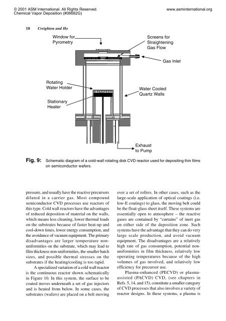
Fig. 9: Schematic diagram of a cold-wall rotating disk <strong>CVD</strong> reac<strong>to</strong>r used for depositing thin films<br />
on semiconduc<strong>to</strong>r wafers.<br />
pressure, and usually have the reactive precursors<br />
diluted in a carrier gas. Most compound<br />
semiconduc<strong>to</strong>r <strong>CVD</strong> processes use reac<strong>to</strong>rs of<br />
this type. Cold wall reac<strong>to</strong>rs have the advantages<br />
of reduced deposition of material on the walls,<br />
which means less cleaning, lower thermal loads<br />
on the substrates because of faster heat-up and<br />
cool-down times, lower energy consumption, and<br />
the avoidance of vacuum equipment. The primary<br />
disadvantages are larger temperature nonuniformities<br />
on the substrate, which may lead <strong>to</strong><br />
film thickness non-uniformities, the smaller batch<br />
sizes, and possible thermal stresses on the<br />
substrates if the heating/cooling is <strong>to</strong>o rapid.<br />
A specialized variation of a cold wall reac<strong>to</strong>r<br />
is the continuous reac<strong>to</strong>r shown schematically<br />
in Figure 10. In this system, the surface <strong>to</strong> be<br />
coated moves underneath a set of gas injec<strong>to</strong>rs<br />
and is heated from below. In some cases, the<br />
substrates (wafers) are placed on a belt moving<br />
www.asminternational.org<br />
over a set of rollers. In other cases, such as the<br />
large-scale application of optical coatings (i.e.<br />
low-E coatings) <strong>to</strong> glass, the moving belt could<br />
be the float-glass sheet itself. These systems are<br />
essentially open <strong>to</strong> atmosphere – the reactive<br />
gases are contained by “curtains” of inert gas<br />
on either side of the deposition zone. Such<br />
systems have the advantage that they can do very<br />
large scale production, and avoid vacuum<br />
equipment. The disadvantages are a relatively<br />
high rate of gas consumption, potential nonuniformities<br />
in film thickness, relatively low<br />
operating temperatures because of the high<br />
volumes of gas involved, and relatively low<br />
efficiency for precursor use.<br />
Plasma-enhanced (PE<strong>CVD</strong>) or plasmaassisted<br />
(PA<strong>CVD</strong>) <strong>CVD</strong>, (see chapters in<br />
Refs. 5, 14, and 15), constitute a smaller category<br />
of <strong>CVD</strong> processes that also involves a variety of<br />
reac<strong>to</strong>r designs. In these systems, a plasma is