RUN-AROUNd-cOIL-SySTEM ENERGy REcOvERy - AL-KO
RUN-AROUNd-cOIL-SySTEM ENERGy REcOvERy - AL-KO
RUN-AROUNd-cOIL-SySTEM ENERGy REcOvERy - AL-KO

Create successful ePaper yourself
Turn your PDF publications into a flip-book with our unique Google optimized e-Paper software.
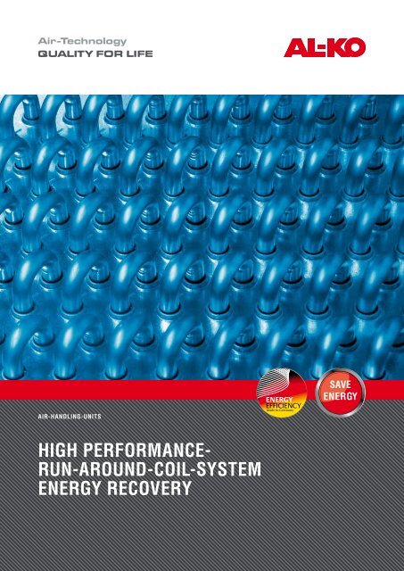
AIR-HANdLING-UNITS<br />
HIGH PERfORMANcE-<br />
<strong>RUN</strong>-<strong>AROUNd</strong>-<strong>cOIL</strong>-<strong>SySTEM</strong><br />
<strong>ENERGy</strong> <strong>REcOvERy</strong>
Benefits of energy recovery<br />
The heat capacity transferred to the out-<br />
side air is not generated afresh but re-<br />
covered through heat recovery from the<br />
extract air. The use of heat recovery units<br />
in air-conditioning-systems results in a<br />
higher capital investment but results in<br />
much lower operation costs. A feasibility<br />
study determines whether the installation<br />
of a heat recovery unit is economic.<br />
Reasons for using a heat<br />
recovery system:<br />
I Capacity reduction for heat generation<br />
I Reduction of annual heating energy<br />
consumption<br />
I Capacity reduction for cooling. This<br />
means a scaling down and saving of<br />
investment in heating coils, pipelines,<br />
pumps, cooling systems, refrigeration<br />
plant, cooling towers and cooling coils.<br />
I Reduction of the annual cooling energy<br />
consumption, thus lower operating<br />
costs<br />
I Reduction in environmental pollution<br />
Supporting frame for Hydraulic components Heat recovery system according to VDI 2071<br />
The most important heat<br />
recovery systems<br />
Recuperators<br />
The hot and cold air-flows are directed<br />
along common interfaces through which<br />
the heat is transferred.<br />
Regenerators<br />
Heat and possibly humidity exchange via<br />
contact surfaces. Hot and cold air flows<br />
physically separated through the heating<br />
wheel. This absorbs the heat in the ex-<br />
tract air and passes it to the supply air.<br />
Run-around-coil-systems<br />
The heat recovery unit is made up of se-<br />
veral heat exchangers. The energy is<br />
transferred indirectly using heat transfer<br />
medium via the interface between the<br />
hot air and the heat transfer medium<br />
and the interfaces between the energy<br />
heat transfer medium and the cold air.
Run-around-coil-systems<br />
In the run-around-coil-system the heat<br />
exchange elements for cooling are in-<br />
tegrated into the extract air-flow and for<br />
heating in the outside air-flow. A pipe<br />
system connects the two coils and serves<br />
as a energy transport medium. The circu-<br />
lating water-glycol fluid removes the heat<br />
energy from the hot extract air and trans-<br />
fers it to the cold outside air.<br />
Heat exchangers with special<br />
water conduit circuit<br />
<strong>AL</strong>-<strong>KO</strong> HEHR (High Efficieny Heat Recovery)<br />
The <strong>AL</strong>-<strong>KO</strong> run-around-coil-system<br />
achieves the highest possible heat re-<br />
covery values considering construc-<br />
tional criteria, like hydraulic circuit,<br />
<strong>AL</strong>-<strong>KO</strong> standard system design<br />
Air-flow ratio outside / exhaust<br />
Air velocity on corrugated exchanger surface<br />
Temperature efficiency outside air<br />
Inlet, fresh air<br />
Outlet, fresh air<br />
Inlet, exhaust air<br />
Outlet, exhaust air<br />
Glycol content, Antifrogen N<br />
r.h. = relative humidity<br />
geometry and heat flow capacity. The<br />
capacity of the system can be adjusted<br />
to high demands for optimal achievement<br />
of economic criteria.<br />
1 : 1<br />
2 m/s<br />
70 %<br />
-12 °C / 85 % r. h.<br />
11.8 °C / 13,2 % r. h.<br />
22 °C / 10 % r. h.<br />
-1.8 °C / 50 % r. h.<br />
25 %
System description<br />
Operation of the <strong>AL</strong>-<strong>KO</strong><br />
run-around-coil-system<br />
I Use of high performance heat exchangers<br />
in a multiple countercurrent circuit. This<br />
achieves high annual utilisation ratios<br />
of 80 %.<br />
I Each heat exchanger has only one mode<br />
of air-flowing through (fresh or extract<br />
air) so that germs and contamination<br />
cannot be transferred.<br />
I The system is used during the winter<br />
period to pre-heat the fresh air and in<br />
the summer to pre-cool the fresh air<br />
through adiabatic cooling of the ex-<br />
tract air.<br />
I Because of humidification of the ex-<br />
tract air during summer period the air<br />
is cooled and the cooling transferred<br />
to the supply air. Humidity cannot be<br />
transferred between the air-flows Be-<br />
cause the exhaust air temperature is<br />
raised in the exhaust air heat exchanger,<br />
it leaves the building without moisture.<br />
I Depending on the type of humidifier<br />
(evaporation humidifier, high pressure<br />
nebuliser, air washer) the humidification<br />
is able to use service water, demin-<br />
eralized or adul terate water.<br />
I The <strong>AL</strong>-<strong>KO</strong> outside air heater can be<br />
divided in accordance with VDI 6022.<br />
The defroster with wide fin spacing, in-<br />
stalled before the filter, raises the out-<br />
side air temperature sufficiently to avoid<br />
frost formation on the filter medium<br />
and thus ensures compliance with the<br />
relative humidity required by VDI 6022.<br />
ETA<br />
SUP<br />
performance<br />
control<br />
pump-hotwater<br />
50/30<br />
I For dehumidifying an additional heat<br />
recovery system exchanger is installed<br />
after the dehumidifying cooler. During<br />
dehumidifying operation the energy me-<br />
dium will first be directed over the heat<br />
recovery reheater to raise the supply air<br />
temperature. The thereby reduced water<br />
temperature considerably reduces the<br />
outlet temperature at the heat recovery<br />
coil. This system circuit saves approximately<br />
20 % cooling capacity.<br />
Hybrid humidifier<br />
ZL<br />
M<br />
MID<br />
PTH<br />
DVE<br />
M VE<br />
SN<br />
M<br />
Hydraulic<br />
Modul<br />
pump-hotwater<br />
50/30<br />
5 2 4 3 2<br />
EHA<br />
ODA
HEHR run-around-coil-system design<br />
I The division in to separate self-sufficient<br />
systems ensures a very high operational<br />
safety and optimal energy transfer.<br />
The heat transfer medium impinges<br />
directly on the heater and cooler. This<br />
design removes the need for an inter-<br />
mediate medium and additional medium<br />
pumps.<br />
I All hydraulic components needed for<br />
the operation are contained on a supporting<br />
frame.<br />
I Cooler and heater are tubed and connected<br />
in accordance with proven<br />
layouts.<br />
I This energy transfer concept is installed<br />
at the factory and piped together<br />
on site by customer installers. There is<br />
no requirement for factory specialists<br />
for this system. The same applies for<br />
servicing and maintenance. All heat exchangers<br />
can be high-pressure cleaned<br />
up to the core.<br />
I The excellent performance values of the<br />
<strong>AL</strong>-<strong>KO</strong>-systems result in a short amortisation<br />
period.<br />
Heat exchangers:<br />
The standardised <strong>AL</strong>-<strong>KO</strong> heat exchangers<br />
consist as standard of copper tubes with<br />
expanded aluminium fins and stainless<br />
steel frame. For increased requirements<br />
the multifarious material combinations<br />
are further enhanced by high quality coat-<br />
ings from two component epoxy resin<br />
or polyamide. The heat exchangers are<br />
designed around the principle of multiple<br />
countercurrents. The heat exchangers<br />
can be completely drained and vented
<strong>AL</strong>-<strong>KO</strong> Air-Technology – extract of references<br />
Project SUP total<br />
m 3 /h<br />
<strong>AL</strong>-<strong>KO</strong> THERM GmbH<br />
Hauptstraße 248 - 250<br />
89343 Jettingen-Scheppach<br />
Phone (+49) 82 25 / 39 - 269<br />
Fax (+49) 82 25 / 39 - 271<br />
E-Mail madelene.laeth@al-ko.de<br />
www.al-ko.com<br />
ETA total<br />
m 3 /h<br />
Number<br />
of units<br />
Heat<br />
recovery<br />
Energy<br />
recovery<br />
Re-heating<br />
during<br />
summ time<br />
via energy<br />
recovery<br />
Run-<br />
around-<br />
coil-<br />
system<br />
Adiabatic<br />
humidifying<br />
of ETA<br />
Aircabin Laupheim 382 000 382 000 6 + 6 X X<br />
Bio Centrum Köln 264 000 220 800 6 + 9 X X<br />
Böhringer Ingelheim 27 500 27 500 1 + 1 X<br />
Creavis Marl I. BA 58 300 51 450 5 + 4 X X X<br />
Creavis Marl II. BA 59 500 45 500 6 + 5 X X<br />
Diakonie Bremen 38 000 38 000 1 + 3 X X X<br />
Ehrmann Moskau 50 000 50 000 1 + 1 X<br />
FHG IZI Labore Leipzig 9 000 9 000 2 + 2 X X<br />
Franziskus Stift Lohne 35 000 35 000 1 + 1 X<br />
Fraunhofer Erlangen II. BA 52 650 52 650 6 + 6 X<br />
Fraunhofer ITEM Hannover 83 000 71 700 1 + 2 X X X<br />
Main Station Dresden 43 150 44 120 3 + 3 X<br />
Heiligenhafen 21 080 21 080 2 + 2 X<br />
IFOK Rostock 64 000 64 000 4 + 4 X<br />
Jogu Mainz lecture rooms 26 315 19 425 1 + 1 X<br />
Clinic Siloah 10 600 10 850 1 + 1 X<br />
Maritim Hotel Berlin 10 600 10 600 1 + 1 X<br />
Coiseum Heilgenhafen 10 000 10 000 X<br />
PTB Braunschweig 30 000 30 000 1 + 1 X X<br />
Rehab Kirchberg Luxembourg 129 200 129 200 9 + 9 X<br />
Residenztheatre München 9 000 8 500 1 + 2 X X<br />
Rietberg museum Schweiz 20 000 1 X<br />
Schülke & Mayr 35 000 38 000 1 + 1 X X<br />
Technic centre Warnemünde 29 275 29 590 1 + 1 X<br />
TIH Hannover 23 000 23 000 1 + 1 X X<br />
Köln university facilities 254 000 250 000 2 + 7 X X<br />
ERG: Energy recovery (heating, cooling)<br />
Run-around-coil-system: Several air-handling-units connected<br />
Hybrid<br />
humidifying<br />
of ETA