Gas spring GF 10/22 - AL-KO
Gas spring GF 10/22 - AL-KO
Gas spring GF 10/22 - AL-KO
- TAGS
- www4.al-ko.de

You also want an ePaper? Increase the reach of your titles
YUMPU automatically turns print PDFs into web optimized ePapers that Google loves.
<strong>22</strong><br />
Connecting parts<br />
and accessories<br />
These pages give a summary<br />
of our extensive range<br />
of high-quality mounting<br />
fittings which provide<br />
optimum connections.<br />
28<br />
Expertise<br />
In this area you can find<br />
details about the possibilities<br />
for custom-made<br />
products, developments<br />
from aeronautical engineering,<br />
and details about<br />
wheel shock absorbers and<br />
overrun brake buffers.<br />
34<br />
Installation<br />
instructions<br />
We will give you important<br />
instructions to ensure that<br />
your gas <strong>spring</strong> operates<br />
in the best way possible.<br />
3
The company<br />
<strong>AL</strong>-<strong>KO</strong> damping technology – nothing is too much trouble<br />
We provide<br />
... creative minds, that develop<br />
innovative products to meet your needs<br />
in a skilled and professional manner<br />
... experienced hands, which have a good<br />
command of the technologies involved, and<br />
produce quality products<br />
... likeable employees, who are there for you<br />
and will be happy to help you in your product<br />
selection<br />
Send us your drawing and we will<br />
design and produce gas <strong>spring</strong>s for you that<br />
are tailored to meet your individual needs!<br />
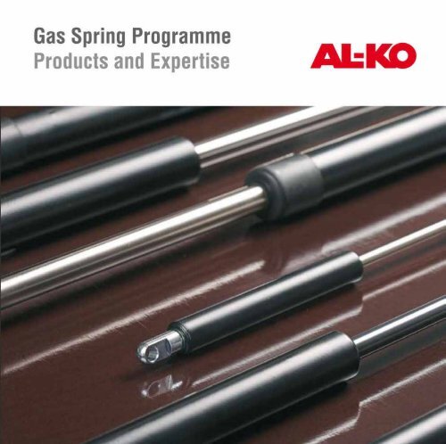
4 <strong>AL</strong>-<strong>KO</strong> <strong>Gas</strong> <strong>spring</strong> range<br />
Your contact<br />
<strong>AL</strong>-<strong>KO</strong> Dämpfungstechnik GmbH<br />
Bahnhofstr. 2-4<br />
04746 Hartha - Germany<br />
Fon: +49 (0)34328 67 0<br />
Fax: +49 (0)34328 67 <strong>22</strong>6<br />
info.hartha@al-ko.de<br />
www.al-ko.de
<strong>AL</strong>-<strong>KO</strong><br />
Our products<br />
■ are easy and safe solutions to be used for<br />
moving heavy components<br />
■ meet the highest quality requirements,<br />
therefore ensuring a long service life<br />
■ provide increased safety for the machine<br />
operating staff<br />
■ are technically functional and aesthetical<br />
■ reduce the maintenance and repair times to<br />
your plant and machinery<br />
Company<br />
55
Product summary<br />
<strong>Gas</strong> <strong>spring</strong>s<br />
Spring characteristic curve x = F 2 / F 1<br />
■ Insertion force: an<br />
external force is<br />
greater than the force<br />
of the gas <strong>spring</strong><br />
Basic type<br />
ø Diameter<br />
piston rod/<br />
cylinder in mm<br />
<strong>GF</strong> 6/15<br />
<strong>GF</strong> 8/19<br />
<strong>GF</strong> <strong>10</strong>/<strong>22</strong><br />
<strong>GF</strong> <strong>10</strong>/28<br />
<strong>GF</strong> 14/28<br />
F R max<br />
( N )<br />
40<br />
60<br />
60<br />
60<br />
<strong>10</strong>0<br />
x = F 2 / F 1<br />
( ≈ )<br />
6 <strong>AL</strong>-<strong>KO</strong> <strong>Gas</strong> <strong>spring</strong> range<br />
■ Extension force:<br />
the external force is<br />
smaller than the force<br />
of the gas <strong>spring</strong><br />
1.4<br />
1.4<br />
1.4<br />
1.2<br />
1.4<br />
Stroke C<br />
5 5<br />
0<br />
F 1<br />
Extension force<br />
F R<br />
■ Frictional force: the difference<br />
between the insertion<br />
and extension forces is<br />
the result of the frictional<br />
force FR.<br />
F 2 F 4<br />
F 3<br />
Insertion force<br />
Force F (N)<br />
Connecting<br />
part<br />
Cylinder pipe<br />
Coating:<br />
epoxy resin<br />
lacquer<br />
Piston rod<br />
nitrided<br />
black/silver<br />
Connecting part
Basic type<br />
ø Diameter piston rod/<br />
cylinder in mm<br />
Non-lockable<br />
<strong>GF</strong> 6/15<br />
<strong>GF</strong> 8/19<br />
<strong>GF</strong> <strong>10</strong>/<strong>22</strong><br />
<strong>GF</strong> <strong>10</strong>/28<br />
<strong>GF</strong> 14/28<br />
OPTI LIFT<br />
(Non-lockable)<br />
<strong>GF</strong>Ba 14<br />
<strong>GF</strong>Bb 14<br />
Lockable<br />
G <strong>10</strong>/28<br />
Explanation<br />
Different extension speeds can be achieved<br />
■ The best solution for moving and/or balancing<br />
loads<br />
■ Absorb movements and therefore reduce<br />
the maintenance and repair times of your<br />
machinery<br />
■ One side of the gas <strong>spring</strong> is secured onto a<br />
roll so that its position changes according to<br />
the angle of the flap ➭ equal expenditure of<br />
energy for opening and closing<br />
■ Has all the advantages of a non-blockable<br />
gas <strong>spring</strong> with the additional possibility of<br />
being able to locate a load in any position<br />
Stroke C<br />
(in mm)<br />
50 ... 200<br />
60 ... 300<br />
60 ... 425<br />
60 ... 425<br />
50 ... 500<br />
45 ... 300<br />
Extension<br />
force F 1 (N)<br />
20 ... 350<br />
80 ... 700<br />
<strong>10</strong>0 ... 1250<br />
<strong>10</strong>0 ... 1250<br />
200 ... 2500<br />
400 ... 1<strong>10</strong>0<br />
400 ... 1500<br />
200 ... 900<br />
Page<br />
8<br />
<strong>10</strong><br />
12<br />
14<br />
16<br />
18<br />
18<br />
20<br />
7
Extended length E ± 2<br />
<strong>Gas</strong> <strong>spring</strong> <strong>GF</strong> 6/15<br />
Stroke C<br />
∅ 15<br />
∅ 6<br />
M 5<br />
6<br />
8 <strong>AL</strong>-<strong>KO</strong> <strong>Gas</strong> <strong>spring</strong> range<br />
6 thick<br />
Stroke<br />
(mm)<br />
∅ 6.1<br />
50<br />
75<br />
<strong>10</strong>0<br />
125<br />
150<br />
175<br />
200<br />
9<br />
16<br />
Extended<br />
length (mm)<br />
134<br />
184<br />
234<br />
284<br />
334<br />
384<br />
434<br />
20<br />
<strong>10</strong><br />
5<br />
∅ 5<br />
Order<br />
number<br />
280 452<br />
280 453<br />
280 454<br />
280 455<br />
280 456<br />
280 457<br />
280 458<br />
Special solutions available on request<br />
<strong>22</strong><br />
9 <strong>10</strong><br />
M 5<br />
SW 7<br />
18<br />
■ Extension force F 1<br />
20 - 350 N<br />
■ Extension speed<br />
0.2 - 0.4 ms -1<br />
11 12<br />
SW 8<br />
M 6<br />
■ Length of the shock absorbing<br />
action 20 ± <strong>10</strong> mm<br />
■ Admissible load in the<br />
direction of traction: ≤ 2000 N<br />
with plastic ball socket: ≤ 1500 N
Product solutions<br />
9 <strong>AL</strong>-<strong>KO</strong> <strong>Gas</strong> <strong>spring</strong> range 9<br />
<strong>AL</strong>-<strong>KO</strong>
Extended length E ± 2<br />
<strong>Gas</strong> <strong>spring</strong> <strong>GF</strong> 8/19<br />
Stroke C<br />
∅ 19<br />
∅ 8<br />
M 6<br />
8<br />
<strong>10</strong> <strong>AL</strong>-<strong>KO</strong> <strong>Gas</strong> <strong>spring</strong> range<br />
<strong>10</strong> thick<br />
∅ 8.1<br />
Stroke<br />
(mm)<br />
75<br />
<strong>10</strong>0<br />
125<br />
150<br />
175<br />
200<br />
<strong>22</strong>5<br />
250<br />
300<br />
16<br />
Extended<br />
length (mm)<br />
203<br />
253<br />
303<br />
353<br />
403<br />
453<br />
503<br />
553<br />
653<br />
24<br />
12<br />
6<br />
∅ 6<br />
Order<br />
number<br />
280 000<br />
280 001<br />
280 002<br />
280 003<br />
283 683<br />
280 004<br />
282 823<br />
280 005<br />
280 006<br />
Special solutions available on request<br />
25<br />
13.5 13<br />
SW 8<br />
M 8<br />
18<br />
■ Extension force F 1<br />
80 - 700 N<br />
■ Extension speed<br />
0.1 - 0.3 ms -1<br />
13.5 13<br />
SW 13<br />
M 8<br />
■ Length of the shock absorbing<br />
action 20 ± <strong>10</strong> mm<br />
■ Admissible load in the<br />
direction of traction: ≤ 3000 N<br />
with plastic ball socket: ≤ 1500 N
Product solutions<br />
11 <strong>AL</strong>-<strong>KO</strong> <strong>Gas</strong> <strong>spring</strong> range 11<br />
<strong>AL</strong>-<strong>KO</strong>
Extended length E ± 2<br />
<strong>Gas</strong> <strong>spring</strong> <strong>GF</strong> <strong>10</strong>/<strong>22</strong><br />
Stroke C<br />
∅ <strong>22</strong><br />
∅ <strong>10</strong><br />
M 8<br />
<strong>10</strong><br />
12 <strong>AL</strong>-<strong>KO</strong> <strong>Gas</strong> <strong>spring</strong> range<br />
<strong>10</strong> thick<br />
∅ 8.1<br />
Stroke<br />
(mm)<br />
75<br />
<strong>10</strong>0<br />
125<br />
150<br />
175<br />
200<br />
250<br />
250<br />
300<br />
350<br />
400<br />
16<br />
Extended<br />
length (mm)<br />
2<strong>10</strong><br />
260<br />
3<strong>10</strong><br />
360<br />
4<strong>10</strong><br />
460<br />
560<br />
6<strong>10</strong><br />
660<br />
760<br />
860<br />
32<br />
16<br />
Order<br />
number<br />
280 007<br />
280 008<br />
280 009<br />
280 0<strong>10</strong><br />
283 595<br />
280 011<br />
280 012<br />
282 950<br />
280 013<br />
280 775<br />
280 778<br />
Special solutions available on request<br />
8<br />
∅ 8<br />
30<br />
13 16<br />
SW 11<br />
M 8<br />
18<br />
■ Extension force F 1<br />
<strong>10</strong>0 - 1250 N<br />
■ Extension speed<br />
0.1 - 0.3 ms -1<br />
13.5 13<br />
SW 13<br />
M 8<br />
■ Length of the shock absorbing<br />
action 20 ± <strong>10</strong> mm<br />
■ Admissible load in the<br />
direction of traction: ≤ 3000 N<br />
with plastic ball socket: ≤ 1500 N
Product solutions<br />
13 <strong>AL</strong>-<strong>KO</strong> <strong>Gas</strong> <strong>spring</strong> range 13<br />
<strong>AL</strong>-<strong>KO</strong>
Extended length E ± 2<br />
<strong>Gas</strong> <strong>spring</strong> <strong>GF</strong> <strong>10</strong>/28<br />
Stroke C<br />
∅ 28<br />
∅ <strong>10</strong><br />
M 8<br />
<strong>10</strong><br />
14 <strong>AL</strong>-<strong>KO</strong> <strong>Gas</strong> <strong>spring</strong> range<br />
<strong>10</strong> thick<br />
∅ 8.1<br />
Stroke<br />
(mm)<br />
75<br />
<strong>10</strong>0<br />
125<br />
150<br />
200<br />
250<br />
300<br />
350<br />
400<br />
16<br />
Extended<br />
length (mm)<br />
2<strong>10</strong><br />
260<br />
3<strong>10</strong><br />
360<br />
460<br />
560<br />
660<br />
760<br />
860<br />
32<br />
16<br />
8<br />
∅ 8<br />
Order<br />
number<br />
280 728<br />
280 729<br />
280 730<br />
280 731<br />
280 732<br />
280 727<br />
280 733<br />
281 739<br />
281 740<br />
Special solutions available on request<br />
30<br />
13 16<br />
SW 11<br />
M 8<br />
18<br />
■ Extension force F 1<br />
<strong>10</strong>0 - 1250 N<br />
■ Extension speed<br />
0.1 - 0.3 ms -1<br />
13.5 13<br />
SW 13<br />
M 8<br />
■ Length of the shock absorbing<br />
action 20 ± <strong>10</strong> mm<br />
■ Admissible load in the<br />
direction of traction: ≤ 3000 N<br />
with plastic ball socket: ≤ 1500 N
Product solutions<br />
15 <strong>AL</strong>-<strong>KO</strong> <strong>Gas</strong> <strong>spring</strong> range 15<br />
<strong>AL</strong>-<strong>KO</strong>
Extended length E ± 2<br />
<strong>Gas</strong> <strong>spring</strong> <strong>GF</strong> 14/28<br />
Stroke C<br />
∅ 28<br />
∅ 14<br />
M <strong>10</strong><br />
9.5<br />
16 <strong>AL</strong>-<strong>KO</strong> <strong>Gas</strong> <strong>spring</strong> range<br />
Stroke<br />
(mm)<br />
<strong>10</strong>0<br />
150<br />
200<br />
250<br />
275<br />
300<br />
300<br />
350<br />
400<br />
400<br />
450<br />
500<br />
12 thick<br />
∅ 8.1<br />
Extended<br />
length (mm)<br />
268<br />
368<br />
468<br />
568<br />
618<br />
668<br />
718<br />
768<br />
868<br />
918<br />
968<br />
<strong>10</strong>68<br />
16<br />
Order<br />
number<br />
280 694<br />
280 711<br />
280 493<br />
280 494<br />
280 749<br />
280 495<br />
282 967<br />
280 496<br />
280 497<br />
283 577<br />
280 498<br />
280 499<br />
Special solutions available on request<br />
40<br />
20<br />
<strong>10</strong><br />
∅ <strong>10</strong><br />
■ Extension force F 1<br />
200 - 2500 N<br />
■ Extension speed<br />
0.1 - 0.3 ms -1<br />
35<br />
16 20<br />
SW 13<br />
■ Length of the shock absorbing<br />
action 20 ± <strong>10</strong> mm<br />
■ Admissible load in the<br />
direction of traction: ≤ 5000 N<br />
M <strong>10</strong>
Product solutions<br />
17 <strong>AL</strong>-<strong>KO</strong> <strong>Gas</strong> <strong>spring</strong> range<br />
<strong>AL</strong>-<strong>KO</strong><br />
17
<strong>Gas</strong> <strong>spring</strong> OPTI LIFT<br />
d<br />
Close<br />
18 <strong>AL</strong>-<strong>KO</strong> <strong>Gas</strong> <strong>spring</strong> range<br />
One side of the gas <strong>spring</strong> is secured onto a<br />
roll so that its position changes according to<br />
the angle of the flap.<br />
u<br />
F1<br />
a<br />
90<br />
Blocking support<br />
Type<br />
<strong>GF</strong>Ba 14<br />
<strong>GF</strong>Bb 14<br />
<strong>Gas</strong> <strong>spring</strong><br />
F 1 (N)<br />
400 - 1<strong>10</strong>0<br />
400 - 1500<br />
G Open<br />
Web guide<br />
α<br />
d (mm)<br />
809<br />
1<strong>10</strong>0<br />
The energy expenditures required for<br />
opening and closing are equally as low as<br />
each other due to the constant optimum<br />
adjustment position.<br />
Advantages:<br />
■ Easy movement of large and heavy flaps<br />
■ Particularly even travel with constantly<br />
low expenditure of energy<br />
Extension force F 1 :<br />
F 1 = G · a · k<br />
G: Flap weight (kg)<br />
a: Balance point distance (mm)<br />
k: Calculation constants according to table<br />
when using two gas <strong>spring</strong>s per flap<br />
u (mm)<br />
193<br />
251<br />
k<br />
0.02025<br />
0.01660<br />
Our employees carry out calculation and design; special solutions available on request<br />
∙ max (°)<br />
86<br />
86
Force in N<br />
Force in N<br />
Product solutions<br />
19 <strong>AL</strong>-<strong>KO</strong> <strong>Gas</strong> <strong>spring</strong> range 19<br />
<strong>AL</strong>-<strong>KO</strong><br />
150<br />
<strong>10</strong>0<br />
50<br />
0<br />
-50<br />
-<strong>10</strong>0<br />
-150<br />
150<br />
<strong>10</strong>0<br />
50<br />
0<br />
-50<br />
-<strong>10</strong>0<br />
-150<br />
Handling load path - standard gas <strong>spring</strong><br />
0 6 12 18 25 31 37 43 49 55 61 68 74 80 86<br />
Opening in °<br />
Handling load path OPTILIFT<br />
0 6 12 18 25 31 37 43 49 55 61 68 74 80 86<br />
Opening in °
Extended length E ± 2<br />
16.5<br />
<strong>Gas</strong> <strong>spring</strong> G <strong>10</strong>/28<br />
lockable, fixed<br />
Stroke C<br />
∅ 4<br />
∅ 28<br />
∅ <strong>10</strong><br />
M <strong>10</strong> x 1<br />
6 ± 1,5<br />
M <strong>10</strong><br />
20 <strong>AL</strong>-<strong>KO</strong> <strong>Gas</strong> <strong>spring</strong> range<br />
9.5<br />
Stroke<br />
(mm)<br />
45<br />
60<br />
90<br />
120<br />
150<br />
180<br />
2<strong>10</strong><br />
240<br />
270<br />
300<br />
12 thick<br />
* without mounting fittings<br />
∅ 8.1<br />
Extended<br />
length* (mm)<br />
197.5<br />
242.5<br />
3<strong>22</strong>.5<br />
392.5<br />
462.5<br />
532.5<br />
602.5<br />
672.5<br />
742.5<br />
783.5<br />
16<br />
Order<br />
number<br />
1217982<br />
1217983<br />
1218151<br />
1218152<br />
1218153<br />
1218154<br />
1218155<br />
1218156<br />
1218157<br />
1218158<br />
Special solutions available on request<br />
40<br />
20<br />
<strong>10</strong><br />
∅ <strong>10</strong><br />
■ Extension force F 1<br />
200 N bis 900 N<br />
35<br />
■ Entire stroke hydraulically<br />
absorbed<br />
■ Permissible load in<br />
insertion direction: 5 x F 1<br />
extension direction: ≤ 3000 N<br />
■ Deblocking force<br />
≤ 200 N with a deblocking<br />
distance of 3,5 mm<br />
16 20<br />
SW 13<br />
M <strong>10</strong>
Product solutions 21 <strong>AL</strong>-<strong>KO</strong> <strong>Gas</strong> <strong>spring</strong> range<br />
21<br />
<strong>AL</strong>-<strong>KO</strong>
Connecting parts and accessories<br />
Provide the best connection<br />
<strong>22</strong> <strong>AL</strong>-<strong>KO</strong> <strong>Gas</strong> <strong>spring</strong> range<br />
The gas <strong>spring</strong>s can only move loads safely if<br />
they have been attached securely and in the<br />
optimum positions. To ensure that this is the<br />
case we have an extensive range of high quality<br />
mounting fittings and accessories to suit<br />
a variety of applications. The following pages<br />
define the technical details for the dimensions<br />
of these parts.<br />
Please feel free to contact us if you have any<br />
questions. Our team shall be pleased to help<br />
you select the appropriate connectors.<br />
We look forward to hearing from you.
Connecting parts<br />
23 <strong>AL</strong>-<strong>KO</strong> <strong>Gas</strong> <strong>spring</strong> range<br />
<strong>AL</strong>-<strong>KO</strong><br />
23
Connecting parts<br />
Overview<br />
24 <strong>AL</strong>-<strong>KO</strong> <strong>Gas</strong> <strong>spring</strong> range<br />
Milled eye a b c d e f<br />
Eye 6.1-6x16 M5 6.1 16 6 M5 <strong>10</strong> 9<br />
Eye 8.1-5x28 M6 8.1 28 5 M6 15 13<br />
Eye <strong>10</strong>.1-5x28 M6 <strong>10</strong>.1 28 5 M6 15 13<br />
Eye 8.1-5x28 M8 8.1 28 5 M8 15 13<br />
Eye 8.1-<strong>10</strong>x30 M<strong>10</strong> 8.1 30 <strong>10</strong> M<strong>10</strong> 18 16<br />
Eyes <strong>10</strong>.1-<strong>10</strong>x30 M<strong>10</strong> <strong>10</strong>.1 30 <strong>10</strong> M<strong>10</strong> 18 16<br />
Moulded eye a b c d e<br />
Eye 8.1-<strong>10</strong>x16 M6 8.1 16 <strong>10</strong> M6 19<br />
Eye 8.1-<strong>10</strong>x23.5 M6 8.1 23.5 <strong>10</strong> M6 15<br />
Eye 8.1-<strong>10</strong>x16 M8 8.1 16 <strong>10</strong> M8 19<br />
Eye <strong>10</strong>.1-<strong>10</strong>x16 M8 <strong>10</strong>.1 16 <strong>10</strong> M8 19<br />
Eye 8.1-12x16 M<strong>10</strong> 8.1 16 12 M<strong>10</strong> 19<br />
Eye <strong>10</strong>.1-12x16 M<strong>10</strong> <strong>10</strong>.1 16 12 M<strong>10</strong> 19<br />
Eye 12.1-12x16 M<strong>10</strong> 12.1 16 12 M<strong>10</strong> 19<br />
Clevis a b c d e<br />
G 5x<strong>10</strong>-M5 5 20 5 M5 <strong>10</strong><br />
G 6x12-M6 6 24 6 M6 12<br />
G 8x16-M8 8 32 8 M8 16<br />
G 6x16-M8 6 32 8 M8 16<br />
G <strong>10</strong>x20-M<strong>10</strong> <strong>10</strong> 40 <strong>10</strong> M<strong>10</strong> 20<br />
G 8x16-M<strong>10</strong> 8 32 8 M<strong>10</strong> 16<br />
Distance piece a b c d<br />
M8x34 M8 34 12 M8<br />
M8x58 M8 58 12 M8<br />
M<strong>10</strong>x<strong>22</strong> M<strong>10</strong> <strong>22</strong> 16 M<strong>10</strong><br />
M<strong>10</strong>x50 M<strong>10</strong> 50 16 M<strong>10</strong><br />
Thickness<br />
c<br />
Thickness<br />
c<br />
b<br />
a<br />
e<br />
∅ c<br />
e<br />
a<br />
d<br />
e<br />
a<br />
d<br />
c<br />
d<br />
b<br />
f<br />
a<br />
b<br />
b<br />
d
c<br />
c<br />
c<br />
c<br />
a<br />
d<br />
b<br />
d<br />
d<br />
f b<br />
sw<br />
f b<br />
f b<br />
l<br />
sw<br />
sw<br />
a<br />
a<br />
a<br />
Hinged joint CS a b c d e f sw<br />
WG CS 8x<strong>22</strong>-M5/M5 M5 <strong>10</strong> <strong>22</strong> M5 8 9 7<br />
WG CS <strong>10</strong>x25-M6/M6 M6 12 25 M6 <strong>10</strong> 11 8<br />
WG CS <strong>10</strong>x25-M6/M8 M8 13 25 M6 <strong>10</strong> 13.5 13<br />
WG CS <strong>10</strong>x19-M6/M8 M8 13 19 M6 <strong>10</strong> 13.5 13<br />
WG CS 13x30-M8/M8 M8 16 30 M8 13 13 11<br />
WG CS 13x30-M8/M<strong>10</strong> M<strong>10</strong> 20 30 M8 13 13 17<br />
WG CS 16x35-M<strong>10</strong>/M<strong>10</strong> M<strong>10</strong> 20 35 M<strong>10</strong> 16 16 13<br />
Hinged joint S a b c d e f sw<br />
WG S <strong>10</strong>x19-M5/M6 M6 12 19 M5 <strong>10</strong> 11 8<br />
WG S <strong>10</strong>x19-M5/M8 M8 13 19 M5 <strong>10</strong> 13.5 13<br />
WG S <strong>10</strong>x19-M6/M8 M8 13 19 M6 <strong>10</strong> 13.5 8<br />
WG S <strong>10</strong>x25-M6/M8 M8 23 25 M6 <strong>10</strong> 13.5 13<br />
WG S <strong>10</strong>x19-M8/M8 M8 13 19 M8 <strong>10</strong> 13.5 13<br />
WG S <strong>10</strong>x19-M8/M6 M6 13 19 M8 <strong>10</strong> 13.5 8<br />
Plastic hinged joint a b c d e f sw<br />
PWG S <strong>10</strong>x18-M5/M6 M5 12 18 M6 <strong>10</strong> 11 8<br />
PWG S <strong>10</strong>x18-M6/M6 M6 12 18 M6 <strong>10</strong> 11 8<br />
PWG S <strong>10</strong>x18-M8/M8 M8 13 18 M8 <strong>10</strong> 13.5 13<br />
Blocking supports<br />
a b c l<br />
Galvanised steel 8.5 15.5 18.5 <strong>10</strong>0 to 500 mm stroke<br />
25
∅ a<br />
g f<br />
sw<br />
l<br />
d<br />
a<br />
a<br />
c<br />
f<br />
b<br />
d<br />
e<br />
e<br />
b<br />
Steel protection pipe a l<br />
<strong>GF</strong>8 24 from 75 mm to 300 mm stroke<br />
<strong>GF</strong><strong>10</strong> 27.5 from 75 mm to 400 mm stroke<br />
<strong>GF</strong>14 34.6 from <strong>10</strong>0 mm to 500 mm stroke<br />
Bearing bracket a b c d e f g<br />
8x15 8 24 15 4.3 45 14 17<br />
6x6 6 24 6 4.3 45 14 17<br />
8x6 8 24 6 4.3 45 14 17<br />
Cap bearing bolt a b sw d e f<br />
Cap bearing bolt 8 19 14 M8 39 12<br />
27
Expertise<br />
Custom-made gas <strong>spring</strong>s<br />
Complete solutions<br />
■ Development of complete solutions<br />
for your special applications<br />
■ Delivery of ready-to-install gas<br />
<strong>spring</strong>s with fittings and assembly<br />
parts<br />
28 <strong>AL</strong>-<strong>KO</strong> <strong>Gas</strong> <strong>spring</strong> range<br />
Individually designed<br />
Individually designed according to your<br />
requirements<br />
■ Printed with your company name<br />
■ In different colours<br />
■ In your desired size and extension<br />
force<br />
Highest corrosion specification<br />
■ Specially produced for use under<br />
extreme challenging conditions, for<br />
example in sand, salt, dust etc.<br />
■ Salt spray tested to guarantee the<br />
best possible corrosion resistance
Expertise<br />
29 <strong>AL</strong>-<strong>KO</strong> <strong>Gas</strong> <strong>spring</strong> range 29<br />
<strong>AL</strong>-<strong>KO</strong>
Expertise<br />
Dampers from aeronautical engineering<br />
<strong>AL</strong>-<strong>KO</strong> LOK: Seat adjustment in aeroplanes<br />
MSA: Secure closing of bins to improve fire prevention<br />
30 <strong>AL</strong>-<strong>KO</strong> <strong>Gas</strong> <strong>spring</strong> range<br />
RATE CONTROL: For easy opening of overhead lockers
The dampers have numerous possible<br />
applications. We use our experience<br />
in the area of aeronautical engineering<br />
to develop product solutions for your<br />
specific needs.<br />
Expertise<br />
31 <strong>AL</strong>-<strong>KO</strong> <strong>Gas</strong> <strong>spring</strong> range 31<br />
<strong>AL</strong>-<strong>KO</strong>
Expertise<br />
Wheel shock absorbers and overrun brake buffers<br />
Hydraulic double-pipe telescopic shock absorbers<br />
■ Absorb wheel vibrations in<br />
vehicles with mechanical and<br />
pneumatic suspension<br />
■ Suitable for transporters and car<br />
trailers up to 3.5 tonnes<br />
Hydro-pneumatic single-pipe dampers<br />
■ Absorb overrun movements of<br />
braked single-axle and tandem<br />
trailers up to a total weight of 3.5<br />
tonnes<br />
■ Stabilise the driving and braking<br />
performance, and therefore increase<br />
safety<br />
32 <strong>AL</strong>-<strong>KO</strong> <strong>Gas</strong> <strong>spring</strong> range<br />
■ Available with a large selection of<br />
fastening fittings<br />
■ Meet the requirements of guideline<br />
EC 71/320 EEC Appendix VIII<br />
■ Are maintenance-free up until the<br />
stated use limit period
Overview of the <strong>AL</strong>-<strong>KO</strong> overrun buffer range<br />
Type<br />
E 8<br />
E <strong>10</strong><br />
Expertise<br />
33 <strong>AL</strong>-<strong>KO</strong> <strong>Gas</strong> <strong>spring</strong> range<br />
<strong>AL</strong>-<strong>KO</strong><br />
Stroke<br />
(mm)<br />
60 - 200<br />
60 - 200<br />
Extended<br />
length (mm)<br />
230 - 605<br />
230 - 605<br />
Ø Piston rod<br />
(mm)<br />
8<br />
<strong>10</strong><br />
Ø Cylinder<br />
(mm)<br />
Overview of the <strong>AL</strong>-<strong>KO</strong> wheel shock absorber range<br />
Type<br />
BG 2<br />
BG 3<br />
K1<br />
K2<br />
Damping power<br />
Tension (N) max<br />
3500<br />
4500<br />
150<br />
80<br />
Damping power<br />
pressure (N) max<br />
800<br />
<strong>10</strong>00<br />
750<br />
1600<br />
24<br />
27<br />
Ø External<br />
Cylinder (mm)<br />
39<br />
45<br />
24<br />
29<br />
Mounting fittings<br />
piston rod<br />
Thread M8 /<br />
M8 x 1<br />
Sleeves<br />
Pipe sections<br />
Thread M8 /<br />
M8 x 1<br />
Sleeves<br />
Pipe sections<br />
Ø External<br />
protective pipe (mm)<br />
47<br />
58<br />
30<br />
38<br />
Mounting fittings<br />
Cylinder<br />
Sleeves<br />
Plates<br />
Pipe sections<br />
Sleeves<br />
Plates<br />
Pipe sections<br />
Stroke<br />
(mm)<br />
70 - 300<br />
70 - 300<br />
70 - 150<br />
70 - 150<br />
33
Installation instructions<br />
Tips and recommendations<br />
The gas <strong>spring</strong>s are designed specifically for your intended application and are supplied<br />
ready-for-installation. Please follow the operating instructions to ensure optimum performance<br />
of your gas <strong>spring</strong>s:<br />
■ Installation takes place with the piston<br />
rod directed downwards<br />
■ Impurities or colouring of the piston<br />
rod destroy the seal of the gas <strong>spring</strong><br />
■ The gas <strong>spring</strong> must not be twisted<br />
■ Avoid the occurrence of bending and<br />
lateral forces; therefore please only use<br />
suitable connecting parts<br />
■ Do not undertake any mechanical<br />
processing of the gas <strong>spring</strong><br />
■ Observe the stated maximum permitted<br />
tensile forces<br />
34 <strong>AL</strong>-<strong>KO</strong> <strong>Gas</strong> <strong>spring</strong> range<br />
■ Do not heat above 120°C!<br />
■ The gas <strong>spring</strong> is subject to high pressure<br />
(up to 200 bar)! Please do not open it!<br />
■ The alignment of the connecting parts in<br />
comparison with each other must be made in<br />
a clockwise direction; please do not dismantle<br />
the fastening fittings<br />
■ The standard gas <strong>spring</strong>s are designed for<br />
use in temperatures ranging from -30°C to<br />
+80°C; obviously we can also produce gas<br />
<strong>spring</strong>s for extreme application conditions if<br />
you require.