Corner Bond Dispensing for BGAs - Nordson Corporation
Corner Bond Dispensing for BGAs - Nordson Corporation
Corner Bond Dispensing for BGAs - Nordson Corporation

You also want an ePaper? Increase the reach of your titles
YUMPU automatically turns print PDFs into web optimized ePapers that Google loves.
www.smtonline.com<br />
ENGINEERING SOLUTIONS FOR PCB MANUFACTURING<br />
S E P T E M B E R 2 0 0 7<br />
Component Traceability p. 16<br />
Placement p. 18<br />
Cost of Ownership p. 24<br />
Cleaning p. 28<br />
SMTA Toolbox p. 36<br />
<strong>Corner</strong> <strong>Bond</strong> <strong>Dispensing</strong><br />
<strong>BGAs</strong>
C O V E R S T O R Y<br />
<strong>Corner</strong> and Edge <strong>Bond</strong><br />
<strong>Dispensing</strong> <strong>for</strong> <strong>BGAs</strong><br />
BY Al Lewis, ASYMTEK<br />
IN<br />
SUMMARY<br />
<strong>Corner</strong> and edge bonding are being used as an<br />
alternative to underfi ll to add mechanical strength<br />
and reliability to <strong>BGAs</strong> and similar chip-scale<br />
packages (CSPs). As adoption of these methods<br />
grows, new techniques <strong>for</strong> applying fl uids <strong>for</strong> corner<br />
bonding emerge.<br />
The underfi ll process was designed to improve<br />
the reliability of fl ip-chip packages, specifically<br />
the fatigue resistance of C4 interconnect<br />
bumps during thermal cycling. The mismatch<br />
in the coeffi cient of thermal expansion (CTE)<br />
between the chip and the substrate induced stress on<br />
interconnect bumps. It was later adopted <strong>for</strong> direct fl ipchip<br />
attach to circuit boards to improve not only resistance<br />
to fatigue, but also reliability during bending and<br />
mechanical shock. BGA packages were designed with<br />
larger interconnection bumps (interconnection balls),<br />
so fatigue during thermal cycling was not an issue.<br />
When BGA packages entered use in portable electronics,<br />
most notably in mobile phones, it was found that<br />
many BGA packages were not reliable during mechanical<br />
shock, such as dropping a phone. Faced with a<br />
reliability crisis in the late 1990s, the industry began<br />
underfi lling BGA packages at the board level. In some<br />
cases, underfi ll was also used on PCBs that were subjected<br />
to bending during assembly and shipment, such<br />
as circuit boards used in PCs and gaming consoles. The<br />
process was to underfi ll BGA packages after refl ow<br />
and cure the underfi ll material prior to fi nal assembly.<br />
Additional dispensing equipment and cure ovens<br />
added undesirable cost to assembly, but it was necessary<br />
to achieve the required reliability.<br />
<strong>Corner</strong> <strong>Bond</strong>ing <strong>BGAs</strong><br />
Underfilling <strong>BGAs</strong> provides more reliability than<br />
needed <strong>for</strong> many products, so the industry began to<br />
explore less costly alternatives.<br />
The corner-bond (sometimes<br />
called corner-glue) process<br />
was developed. In this process,<br />
adhesive similar to surface<br />
mount adhesive (SMA)<br />
is placed on the PCB in dots<br />
at the corner of BGA attachment<br />
points prior to placing<br />
the BGA. When the circuit<br />
board is re-fl owed, the material<br />
cures and provides additional<br />
shock and bending resistance<br />
to the assembly. To<br />
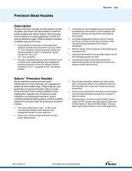
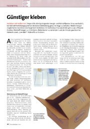
increase reliability, alternate
patterns, such as “L” shapes at the corner,<br />
have been developed (Figure 1).<br />
Although these materials are similar to<br />
SMAs, they have been designed specifi cally<br />
to accommodate interconnect collapse and<br />
self-alignment during refl ow. The principle<br />
advantages of this process are that additional<br />
cure ovens are not required and existing SMA<br />
dispensing equipment could be adapted to<br />
Figure 1. Test vehicle showing corner bond<br />
patterns. Photo courtesy of Henkel.<br />
apply the material. In addition, corner-bonded<br />
<strong>BGAs</strong> often are re-workable, something that<br />
is not practical <strong>for</strong> underfi lled <strong>BGAs</strong>.<br />
Accuracy in amount and position of applying<br />
the fl uid correlates directly with the reliability<br />
of the corner-bonding process. As<br />
noted, standard SMA dispensing equipment<br />
often is used <strong>for</strong> this process, and may suffi ce<br />
depending on the level of reliability needed.<br />
The disadvantage of using this equipment is<br />
that it may not be designed <strong>for</strong> the type of<br />
pattern fl exibility and fl uid accuracy required<br />
<strong>for</strong> higher reliability. Process controls are not<br />
in place to regulate the amount or placement<br />
of fl uid; needle dispensing is not adaptable<br />
enough to create the shapes and patterns being<br />
used in the corner-bonding process. With<br />
more sophisticated dispense patterns, it also<br />
may be diffi cult to keep pace with medium-<br />
to high-volume production typically found in<br />
production lines that place 30,000+ component<br />
per hour (CPH).<br />
It should be noted that “no-flow” underfi<br />
ll techniques share many of the same<br />
process advantages as corner bonding, but<br />
with the added complication of having to<br />
make underfi ll material compatible with<br />
fl ux during refl ow.<br />
Edge <strong>Bond</strong>ing <strong>BGAs</strong><br />
Edge bonding is gaining popularity as an alternative<br />
to underfi ll and corner bonding. In<br />
this process, a BGA package is placed and<br />
reflowed; then an adhesive is dispensed<br />
along the edge or corner of the package. The<br />
material rheology is designed to limit or prevent<br />
capillary fl ow of the material so that it<br />
remains on package edges. The material typically<br />
is heat-cured. Because the edge-bond<br />
material is exposed on the outside of the<br />
package, UV-cure mechanisms also are possible,<br />
providing faster and lowercost<br />
production compared to<br />
heat curing. Edge-bonded<br />
<strong>BGAs</strong> can also be reworked<br />
and visually inspected.<br />
Equipment<br />
Requirements<br />
<strong>for</strong> Underfi ll<br />
Underfill processing requires<br />
dispensing equipment<br />
and a cure oven. Underfi ll<br />
can be done manually, however,<br />
medium- to high-volume<br />
production runs and/or<br />
high-value components demand<br />
automated dispensing.<br />
Typical dispensing equipment<br />
<strong>for</strong> underfi ll features:<br />
• Pre-dispense heat station brings the board<br />
up to temperature <strong>for</strong> underfi lling. The<br />
pre-heat station must accommodate specifi<br />
c temperature ramp rates and/or dualsided<br />
heating techniques to meet production-speed<br />
requirements without inducing<br />
thermal expansion stress.<br />
• Heated dispense station holds the board at<br />
an optimal temperature during underfi ll.<br />
• Automated vision alignment systems: depending<br />
on board layout and package<br />
density, systems with edge-detection algorithms<br />
may be needed <strong>for</strong> precise material<br />
placement.<br />
• Many underfi ll materials<br />
are abrasive to dispensing<br />
equipment, so equipment<br />
must be designed to<br />
accommodate this.<br />
• Underfill material often<br />
has a limited working life,<br />
which requires temperature<br />
management of the<br />
fluid reservoir, tracking<br />
of the working life, and<br />
equipment that can be<br />
cleaned quickly and easily.<br />
• Limited working life also<br />
implies material rheology<br />
changes during production,<br />
which must be accommodated<br />
by calibration.<br />
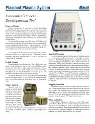
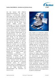
Increasing yield 0.09% can save 25% in cost of ownership<br />
$ per board<br />
0.03<br />
0.02<br />
0.01<br />
0.00<br />
99.90% yield 99.99% yield<br />
C O V E R S T O R Y<br />
• Depending on package size, board layout,<br />
and density, underfi ll equipment may need<br />
to accommodate multiple dispensing steps<br />
that are timed precisely to optimize material<br />
fi llet width and prevent void <strong>for</strong>mation.<br />
• If the package is covered with an RF<br />
shield, jetting is preferred so that the material<br />
can be applied through a hole in the<br />
shield after it is placed.<br />
While many of these features may not<br />
be required, they are justifi ed through<br />
cost of ownership (COO) calculations<br />
that show reduced production cost by improving<br />
production speed, material savings,<br />
or yield. For example, using jetting<br />
technology instead of needle dispensing<br />
can reduce material consumption by 35%<br />
and improve production rates as much as<br />
400%. Figure 2 illustrates the cost of ownership<br />
reduction that can be obtained by a<br />
modest improvement in yield.<br />
Equipment Requirements<br />
<strong>for</strong> <strong>Corner</strong> <strong>Bond</strong>ing<br />
As mentioned, corner bonding can be accommodated<br />
with most SMA equipment.<br />
The following characteristics are differentiated<br />
from the requirements of underfi lling:<br />
• Board heating is not required, eliminating<br />
pre-dispense heat and dispense heat<br />
stations, and potentially allowing <strong>for</strong> a dispenser<br />
with a smaller footprint to reduce<br />
fl oor space and COO.<br />
• <strong>Corner</strong>-bond material may not be abrasive,<br />
which can relax requirements on wetted<br />
parts inside the fl uid-delivery device.<br />
• <strong>Corner</strong>-bond material typically has a longer<br />
working life, reducing cleaning and accommodation<br />
of rheology changes.<br />
• Multiple dispensing steps and timing algorithms<br />
are not required.<br />
Yield<br />
Recurring<br />
Labor<br />
Fixed<br />
Figure 2. Using SEMI E35 cost of ownership modeling<br />
shows savings in improved yield can be dramatic.<br />
Example assumes initial equipment cost of $100,000 at<br />
800 boards/hour production rate.
C O V E R S T O R Y<br />
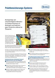
Precision in the placement and volume of material <strong>for</strong> corner<br />
bonding can be critical. The process is new, but guidelines are available.<br />
1-5 <strong>Bond</strong>ing material is placed prior to component placement and<br />
refl ow. For high reliability, the bonding material must not interfere<br />
with the refl ow process. There<strong>for</strong>e, it must be placed in a precise position,<br />
with the correct volume, and in the correct shape, so that it<br />
captures the edge of the package without touching any of interconnect<br />
balls. Features such as jetting technology, material quantity calibration,<br />
and data logging of critical process parameters can reduce<br />
COO by increasing production speed and yield.<br />
Equipment Requirements <strong>for</strong> Edge <strong>Bond</strong>ing<br />
Although edge bonding takes place at a different point in the assembly<br />
process, equipment requirements <strong>for</strong> dispensing edge-bond material<br />
are similar to that of corner bonding, with these exceptions:<br />
• Edge-bond materials that are UV-curable must have fl uid handling<br />
and dispensing systems compatible with UV-cure chemistries.<br />
• The shape and height of the edge-bond material is critical to the<br />
reliability of the fi nal package. Unlike corner bond or underfi ll,<br />
the bonding material often stays in the shape in which it is dispensed.<br />
There<strong>for</strong>e, technologies such as jetting can help provide<br />
fl exibility with high production rates.<br />
• If the edge-bond process is designed so that the material partially<br />
fl ows under the package, board heating may be required.<br />
• Since the material is applied after refl ow, an additional curing step<br />
is required. If UV-cure chemistry is used, a UV-cure oven typically<br />
is faster and requires less production space than heat-cure ovens.<br />
As with corner bonding, edge-bonding reliability depends on the<br />
shape and placement of the bonding material. It is desirable to minimize<br />
the “footprint” of the edge bond, or the area past the edge of<br />
the package that is required <strong>for</strong> bonding. In this case, jetting technology<br />
can provide a speed and material profi le advantage.<br />
Conclusion<br />
The goal of corner- and edge-bonding processes is to improve<br />
board assembly reliability at a cost less than underfi ll. The drive to<br />
reduce production costs can tempt manufacturers to purchase the<br />
lowest-cost equipment. Yield and reliability should be considered<br />
in the process’s total cost of ownership. If the choice of equipment<br />
further reduces reliability, it is possible to lose the intrinsic savings<br />
in material, production time, or fl oor space. SMT<br />
REFERENCES<br />
1 Williams, Ian, “HDI, Overcoming Assembly Challenges,” IPC Intel<br />
Technology Interchange, May 2007.<br />
2 Toleno, Brian, “The Next Big Thing: Self Aligning, Pb-Free Capable<br />
<strong>Corner</strong> Support <strong>for</strong> CSPs,” Henkel, April 2007.<br />
3 Hisert, Jim, “Shock Reliability of <strong>BGAs</strong> Using Underfi ll,” SMT, T, T<br />
January 2007.<br />
4 Alcoe, D.J. Blackwell, K.J. Rai, R., “High reliability BGA package<br />
improvements on module total cost of ownership,” Electronics<br />
Manufacturing Technology Symposium, 2003; IEMT 2003;<br />
IEEE/CPMT/SEMI 28th International.<br />
5 Geok-Leong Tan; Chuan-Yau Hoo; Gerard Chew; Jim-Hee Low;<br />
Nam-Beng Tay; Chakravorty, K.K.; Thiam-Beng Lim, “Reliability<br />
assessment of BGA packages,” proceedings from Electronic<br />
Components and Technology Conference, 1996.<br />
Al Lewis, director of marketing and applications, Asymtek, may be<br />
contacted at (760) 930-3379; alewis@asymtek.com.<br />
Reprinted with revisions to <strong>for</strong>mat, from the September 2007 edition of SURFACE MOUNT TECHNOLOGY<br />
Copyright 2007 by PennWell <strong>Corporation</strong>