Static and Dynamic Balancing of Rigid Rotors
Static and Dynamic Balancing of Rigid Rotors
Static and Dynamic Balancing of Rigid Rotors

You also want an ePaper? Increase the reach of your titles
YUMPU automatically turns print PDFs into web optimized ePapers that Google loves.
Principle <strong>of</strong> <strong>Balancing</strong><br />
A rotor is balanced by placing a cor<br />
rection mass <strong>of</strong> a certain size in a posi<br />
tion where it counteracts the unbal<br />
ance in the rotor. The size <strong>and</strong> posi<br />
tion. <strong>of</strong> the correction mass must be<br />
determined.<br />
The principle <strong>of</strong> performing field<br />
balancing is to make (usually tempo<br />
rary) alterations to the mass distribu<br />
tion <strong>of</strong> the rotor, by adding trial<br />
masses, <strong>and</strong> to measure the resulting<br />
phase <strong>and</strong> magnitude <strong>of</strong> bearing vibra<br />
tion. The effects <strong>of</strong> these trial correc<br />
tions enable the amount <strong>and</strong> position<br />
<strong>of</strong> the required correction mass to be<br />
determined. The values are usually<br />
calculated with the aid <strong>of</strong> a pocket<br />
calculator.<br />
Any fixed point on the bearing ex<br />
periences the centrifugal force due to<br />
the unbalance, once per revolution <strong>of</strong><br />
the rotor. Therefore in a frequency<br />
spectrum <strong>of</strong> the vibration signal, un<br />
balance is seen as an increase in the<br />
vibration at the frequency <strong>of</strong> rotation.<br />
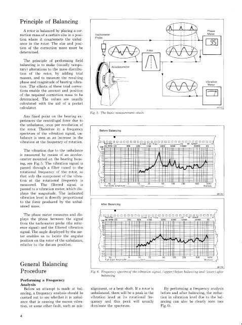
The vibration due to the unbalance<br />
is measured by means <strong>of</strong> an acceler-<br />
ometer mounted on the bearing hous<br />
ing, see Fig. 5. The vibration signal is<br />
passed through a filter tuned to the<br />
rotational frequency <strong>of</strong> the rotor, so<br />
that only the component <strong>of</strong> the vibra<br />
tion at the rotational frequency is<br />
measured. The filtered signal is<br />
passed to a vibration meter, which dis<br />
plays the magnitude. The indicated<br />
vibration level is directly proportional<br />
to the force produced by the unbal<br />
anced mass.<br />
The phase meter measures <strong>and</strong> dis<br />
plays the phase between the signal<br />
from the tachometer probe (the refer<br />
ence signal) <strong>and</strong> the filtered vibration<br />
signal. The angle displayed by the me<br />
ter enables us to locate the angular<br />
position on the rotor <strong>of</strong> the unbalance,<br />
relative to the datum position.<br />
General <strong>Balancing</strong><br />
Fig. 5. The basic measurement chain<br />
Procedure Fig. 6. Frequency spectra <strong>of</strong> the vibration signal, (upper) before balancing <strong>and</strong> (lower) after<br />
balancing<br />
Performing a Frequency<br />
Analysis<br />
Before an attempt is made at bal- alignment, or a bent shaft. If a rotor is By performing a frequency analysis<br />
ancing, a frequency analysis should be unbalanced, there will be a peak in the before <strong>and</strong> after balancing, the reduc-<br />
carried out to see whether it is unbal- vibration level at its rotational fre- tion in vibration level due to the bal<br />
ance that is causing the excess vibra- quency <strong>and</strong> this peak will usually ancing can also be clearly seen (see<br />
tion, or some other fault, such as mis- dominate the spectrum. Fig. 6).<br />
4