The calculation <strong>of</strong> the maximum al lowable residual specific unbalance as sumes that the mass <strong>of</strong> the rotor is evenly distributed about the centre <strong>of</strong> gravity. If the mass <strong>of</strong> the rotor is unevenly distributed, the calculations are a little more complicated. In a perfectly balanced rotor, equal forces act on both ends <strong>of</strong> the rotor when it rotates. If the rotor is shaped as in Fig. 8, however, the forces at each end will be equal, but the allowable residual specific unbalance will be dif ferent for each bearing. The position <strong>of</strong> the centre <strong>of</strong> gravity divides the rotor in the ratio V3 : 2 /3. The sum <strong>of</strong> the moments about the centre <strong>of</strong> grav ity must be zero. Therefore the residu- Fig. 8. A rotor with unevenly distributed mass al specific unbalance at bearing A is 2 /3 <strong>of</strong> the total residual specific unbal ance, while at bearing B it is V3 <strong>of</strong> the total. Selection <strong>of</strong> Trial Masses The specific unbalance is used to calculate the size <strong>of</strong> trial masses, which are used during balancing to make temporary alterations to the mass distribution <strong>of</strong> the rotor, to de- Fig. 9, Determining the position <strong>of</strong> the correction mass termine the relationship between the specific unbalance <strong>and</strong> the bearing vi- n ^ . , , , . . 1 . n . i ,. 3. Measure <strong>and</strong> record the vibration care has been taken with the bailevel <strong>and</strong> phase angle. ancing procedure <strong>and</strong> proper bairn ,. , ,, n n .,U1 ancing equipment, such as that de- To estimate the value ol a suitable . 0i_ ,. . . , j . -i i • li \- r , ^ . , ,, , ,, , - , 4. htop the machine <strong>and</strong> mount a tn- scribed in the section on Instrutnal mass, the mass oi the rotor in kg , . . . i ■, ., • i i ^ ^ ^ ^ , ^ T • i T_- i. 1.x. al mass <strong>of</strong> suitable size arbitrarily mentation, has been used, the level <strong>and</strong> the radius m mm at which the . n ,. . , . , „ . , , ., , , , i , i in the correction circle, i.e. the or residual vibration measured corrections are to be made must be . . . >■•.-, ^ ^ i u n i -^ i i i ,. , ^ ■ i rm n/r • o - j i plane where the correction is to be should be small <strong>and</strong> it should not determined. The Maximum Kesidual i **- , , •• r , ■ i ^ ^ ,i i i ,, , f ■ i made. Mark the position <strong>of</strong> the tri- be necessary to repeat the balanc- Mass MMR, in grammes, is given by: . * ' j al mass. ing procedure. S U X M MMR = ——■ 5. Start up the machine <strong>and</strong> measure Two-Plane (<strong>Dynamic</strong>) <strong>Balancing</strong> Re <strong>and</strong> record the new vibration level The procedure for two-plane bal- where <strong>and</strong> phase angle. ancing is very similar to that for single-plane balancing. In this case, how- S.U. = Specific Unbalance re- 6. Stop the machine <strong>and</strong> remove the ever, two accelerometers must be quired (in g mm/kg) ^^ mass. used, since measurements in two MR = Rotor Mass (kg) planes are required. Unbalance in one . 7. Calculate the values <strong>of</strong> the correc- plane affects the other; this is known Rc - Correction Radius (mm) t[Qn mags <strong>and</strong> angle required? using as the cross effect. Before balancing, a . 1 , . 1 . r. one <strong>of</strong> the methods detailed in the frequency analysis <strong>of</strong> both planes is A suitable trial mass is five to ten gection Qn Calculatim Methods. made. times the value <strong>of</strong> the Maximum Re sidual Mass. 8 jyjount tne correction mass at the The steps involved in two-plane bal- Single-Plane (<strong>Static</strong>) <strong>Balancing</strong> P 0sitl0n indicated by the correc- ancing are as follows: Having made a frequency analysis tl0n , ang ' e : A P os f ve correction <strong>of</strong> the vibration <strong>and</strong> calculated the angle indicates that the angle 1. Mount the accelerometers <strong>and</strong> ta- value <strong>of</strong> a suitable trial mass, the pro- should f be measured m the direc- chometer probe <strong>and</strong> connect them , r • i i u i tion <strong>of</strong> rotation. For a negative cor- to the instruments. cedure for single-plane balancing is as . - , follows- rection angle, measure against the direction <strong>of</strong> rotation, see Fig. 9. 2. Run the machine at its normal op- 6 1. Mount an accelerometer <strong>and</strong> ta- The correction mass should be erating speed*. chometer probe <strong>and</strong> connect them mounted at the same radius as the to the instruments. trial mass. 2. Run the machine at its normal op- 9. Start up the machine again <strong>and</strong> * It is preferable, but not in fact necessary to D3.l9.nc6 s. rotor 9t its scrvicG SDGGCI SPG th.6 section Special <strong>Balancing</strong> Cases for details on erating speed*. measure the residual unbalance. If balancing at less than service speed.
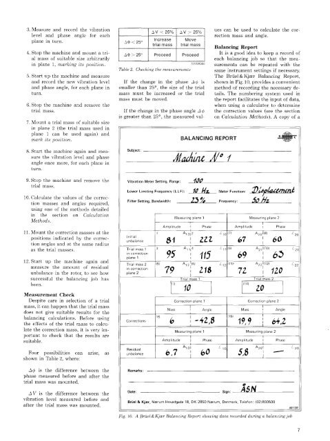
3. Measure <strong>and</strong> record the vibration I I A v < 25°/ I A V > ?5 0 / I ues can ^ e use< AV < 25% A V > 25% ^ to calculate the corlevel <strong>and</strong> phase angle for each rection mass <strong>and</strong> angle. plane in turn. A$