Mastantennen / Mast-Antennas STA 40 M, STA 50 M, STA 60 M
Mastantennen / Mast-Antennas STA 40 M, STA 50 M, STA 60 M
Mastantennen / Mast-Antennas STA 40 M, STA 50 M, STA 60 M

Create successful ePaper yourself
Turn your PDF publications into a flip-book with our unique Google optimized e-Paper software.
<strong><strong>Mast</strong>antennen</strong> / <strong>Mast</strong>-<strong>Antennas</strong><br />
Mechanical Specification<br />
Design<br />
This very robust antenna is the result of decades long experience<br />
with glassfibre reinforced synthetic resins. The electrolytic copper<br />
radiators are embedded into the resin laminate.<br />
The antennas consist of two sections. The lower section with its<br />
base insulator has a length of approx. 3 m. This self-supporting<br />
lower section takes up the upper section by means of a junction<br />
assembly. Upper sections are available with lengths of 1, 2 and<br />
3 meter.<br />
The antenna is absolutely amagnetic.<br />
Required Space<br />
Only a minimum of space is required for this self-supporting outstanding<br />
stiff antenna construction, mounted on a base flange of<br />
230 mm diameter.<br />
On board of ships the antenna shall be mounted in a sloping position<br />
from 5 to 15° in order to avoid oscillation.<br />
Environmental<br />
Due to the extraordinary chemical resistance of the glassfibre reinforced<br />
material the antenna withstands any known marine environmental<br />
stress.<br />
Maintenance<br />
about zero<br />
The antenna shall be cleaned from time to time with sweet water.<br />
In case of oily soil, please, add self detergents to the water.<br />
Spare Parts List<br />
Position Designation Order-Code<br />
1 <strong>STA</strong> <strong>40</strong> M E 107-<strong>60</strong>6<br />
1 <strong>STA</strong> <strong>50</strong> M E 107-<strong>60</strong>7<br />
1 <strong>STA</strong> <strong>60</strong> M E 107-<strong>60</strong>8<br />
1* upper section:<br />
<strong>STA</strong> 10 HV/M (<strong>STA</strong> <strong>40</strong> M) E 107-145<br />
<strong>STA</strong> 20 HV/M (<strong>STA</strong> <strong>50</strong> M) E 107-146<br />
<strong>STA</strong> 30 HV/M (<strong>STA</strong> <strong>60</strong> M) E 107-125<br />
2 Locking nut E 107-224<br />
3 O-Ring E 107-245<br />
4 Lower Section E 107-429<br />
(complete)<br />
ELNA reserves the right to make changes in specifications<br />
without notice.<br />
June 2000<br />
<strong>STA</strong> <strong>40</strong> M, <strong>STA</strong> <strong>50</strong> M, <strong>STA</strong> <strong>60</strong> M<br />
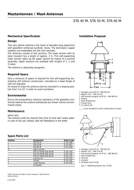
Installation Proposal<br />
1 Hexagon screw M 10 – DIN 933-A2<br />
1 Washer 10.5 – DIN 125-A2<br />
1 Self-locking hexagon nut M 10 – DIN 985-A2<br />
2 Sealing<br />
3 Axial-lengthening<br />
4 Clamp-cone<br />
5 Cu-tube 6 dia<br />
_._._ to be insulated to ovoid condensation of water<br />
1 Hexagon screw M 10 – DIN 933-A2<br />
1 Washer 10.5 – DIN 125-A2<br />
1 Self-locking hexagon nut M 10 – DIN 985-A2<br />
3 Axial-lengthening<br />
4 Terminal<br />
5 Insulator<br />
6 Stranded wire 4-8 dia<br />
pos. 1, Tightening torque max. 20 Nm