Mastantennen / Mast-Antennas STA 40 M, STA 50 M, STA 60 M
Mastantennen / Mast-Antennas STA 40 M, STA 50 M, STA 60 M
Mastantennen / Mast-Antennas STA 40 M, STA 50 M, STA 60 M

Create successful ePaper yourself
Turn your PDF publications into a flip-book with our unique Google optimized e-Paper software.
<strong><strong>Mast</strong>antennen</strong> / <strong>Mast</strong>-<strong>Antennas</strong><br />
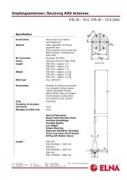
Specification<br />
Frequency range 100 kHz – 30 MHz (receive)<br />
RF power 15 kV eff.<br />
Insulation > 10 7 Ohm<br />
Polarization vertical<br />
Characteristic omnidirectional<br />
Radiator diameter 65 mm (lower section)<br />
Length <strong>STA</strong> <strong>40</strong> M - approx. 39<strong>40</strong> mm<br />
<strong>STA</strong> <strong>50</strong> M - approx. 49<strong>40</strong> mm<br />
<strong>STA</strong> <strong>60</strong> M - approx. 59<strong>40</strong> mm<br />
Weight <strong>STA</strong> <strong>40</strong> M - approx. 11.5 kg<br />
<strong>STA</strong> <strong>50</strong> M - approx. 12.0 kg<br />
<strong>STA</strong> <strong>60</strong> M - approx. 12.5 kg<br />
Colour light grey, similar to RAL 7035<br />
Deflexion at 1<strong>50</strong> km/h wind <strong>STA</strong> <strong>40</strong> M - less than 165 mm<br />
<strong>STA</strong> <strong>50</strong> M - less than 380 mm<br />
<strong>STA</strong> <strong>60</strong> M - less than 870 mm<br />
Max. Bending Stress <strong>STA</strong> <strong>40</strong> M - 990 Nm)<br />
at Base Insulator <strong>STA</strong> <strong>50</strong> M - 1230 Nm)<br />
<strong>STA</strong> <strong>60</strong> M - 1510 Nm)<br />
represents 8 m/s 2<br />
overheeling<br />
acceleration plus 200 km/h wind<br />
Ambient Temperature -<strong>40</strong>° ... <strong>50</strong>° C<br />
Storage Temperature -<strong>40</strong>° ... <strong>60</strong>° C<br />
Application<br />
This antenna is intended to meet the requirements of maritime<br />
mobile services. It should find application wherever on account of<br />
extreme climatical and operational conditions the antenna has to<br />
guarantee max. strength, stiffness, and reliability. It requires very<br />
low maintenance. The antenna mainly operates as a vertically polarized<br />
radiator with an omnidirectional pattern. It can be used as<br />
both transmitting and receiving antenna.<br />
Receiving antennas may be equipped with wideband toroidal core<br />
matching transformers types EAU <strong>60</strong>/2<strong>40</strong> resp. EAU <strong>60</strong>/2<strong>40</strong>/II as<br />
per data sheet.<br />
<strong>STA</strong> = Rod Antenna K = Tilt SSB = internal feeding NDB = Non Directional Radio Beacon<br />
E = Receiving Rod Antenna TR = reinforced SSB/E = external feeding<br />
EAU = Transformer SE = Transmit Antenna PM/M = dark grey (similar to RAL 7000)<br />
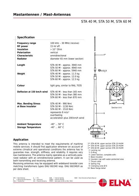
<strong>STA</strong> <strong>40</strong> M, <strong>STA</strong> <strong>50</strong> M, <strong>STA</strong> <strong>60</strong> M<br />
Section A-A<br />
1* <strong>STA</strong> <strong>40</strong> M: upper section <strong>STA</strong> 10 HV/M<br />
1* <strong>STA</strong> <strong>50</strong> M: upper section <strong>STA</strong> 20 HV/M<br />
1* <strong>STA</strong> <strong>60</strong> M: upper section <strong>STA</strong> 30 HV/M<br />
2 Locking nut<br />
3 O-Ring<br />
4 Lower Section, complete with:<br />
5 Base insulator<br />
6 Insulator cap with water-protected area<br />
7 Thrust collar<br />
8 Sailing ring<br />
9 Clamping cone Ø 6<br />
10 Base flange detail
<strong><strong>Mast</strong>antennen</strong> / <strong>Mast</strong>-<strong>Antennas</strong><br />
Mechanical Specification<br />
Design<br />
This very robust antenna is the result of decades long experience<br />
with glassfibre reinforced synthetic resins. The electrolytic copper<br />
radiators are embedded into the resin laminate.<br />
The antennas consist of two sections. The lower section with its<br />
base insulator has a length of approx. 3 m. This self-supporting<br />
lower section takes up the upper section by means of a junction<br />
assembly. Upper sections are available with lengths of 1, 2 and<br />
3 meter.<br />
The antenna is absolutely amagnetic.<br />
Required Space<br />
Only a minimum of space is required for this self-supporting outstanding<br />
stiff antenna construction, mounted on a base flange of<br />
230 mm diameter.<br />
On board of ships the antenna shall be mounted in a sloping position<br />
from 5 to 15° in order to avoid oscillation.<br />
Environmental<br />
Due to the extraordinary chemical resistance of the glassfibre reinforced<br />
material the antenna withstands any known marine environmental<br />
stress.<br />
Maintenance<br />
about zero<br />
The antenna shall be cleaned from time to time with sweet water.<br />
In case of oily soil, please, add self detergents to the water.<br />
Spare Parts List<br />
Position Designation Order-Code<br />
1 <strong>STA</strong> <strong>40</strong> M E 107-<strong>60</strong>6<br />
1 <strong>STA</strong> <strong>50</strong> M E 107-<strong>60</strong>7<br />
1 <strong>STA</strong> <strong>60</strong> M E 107-<strong>60</strong>8<br />
1* upper section:<br />
<strong>STA</strong> 10 HV/M (<strong>STA</strong> <strong>40</strong> M) E 107-145<br />
<strong>STA</strong> 20 HV/M (<strong>STA</strong> <strong>50</strong> M) E 107-146<br />
<strong>STA</strong> 30 HV/M (<strong>STA</strong> <strong>60</strong> M) E 107-125<br />
2 Locking nut E 107-224<br />
3 O-Ring E 107-245<br />
4 Lower Section E 107-429<br />
(complete)<br />
ELNA reserves the right to make changes in specifications<br />
without notice.<br />
June 2000<br />
<strong>STA</strong> <strong>40</strong> M, <strong>STA</strong> <strong>50</strong> M, <strong>STA</strong> <strong>60</strong> M<br />
Installation Proposal<br />
1 Hexagon screw M 10 – DIN 933-A2<br />
1 Washer 10.5 – DIN 125-A2<br />
1 Self-locking hexagon nut M 10 – DIN 985-A2<br />
2 Sealing<br />
3 Axial-lengthening<br />
4 Clamp-cone<br />
5 Cu-tube 6 dia<br />
_._._ to be insulated to ovoid condensation of water<br />
1 Hexagon screw M 10 – DIN 933-A2<br />
1 Washer 10.5 – DIN 125-A2<br />
1 Self-locking hexagon nut M 10 – DIN 985-A2<br />
3 Axial-lengthening<br />
4 Terminal<br />
5 Insulator<br />
6 Stranded wire 4-8 dia<br />
pos. 1, Tightening torque max. 20 Nm
Antennenübertrager / Antenna Matching Transformer<br />
Application<br />
Matching transformer for passive receiving antennas.<br />
When the antenna transformer is used, short rod or wire antennas<br />
(3 to 15 m) can be connected to a coaxial cable. The antenna transformer<br />
considerably improves the efficiency of the receiving antenna,<br />
particularly in the lower frequency range, and protects the<br />
receiver from static charges.<br />
Specification<br />
Dimension (w x d x h) 115 x 115 x 70 mm<br />
Weight 1.7 kg<br />
Ambient temperature -<strong>40</strong> ... +70°C<br />
Storage temperature -<strong>50</strong> ... +80°C<br />
Protection rating IP54<br />
(vertical installation<br />
recommended)<br />
Material casing bronze-cast<br />
Cable inlet (antenna side) cable screw joint PG 13.5<br />
for antenna wire litz d = 4.5 mm<br />
Cable outlet (receiver side) cable screw joint SHV-Erko<br />
for RG 213 U<br />
Input protection lightning arrester (90 V)<br />
Frequency range 0.1 - 30 MHz<br />
Max. permissible power < 4 W<br />
acceptance<br />
Output impedance <strong>50</strong> … 75.<br />
Transformer attenuation < 1 dB<br />
Part-No. E 107 964<br />
All data without tolerance are approximate values.<br />
<strong>STA</strong> = Rod Antenna K = Tilt SSB = internal feeding NDB = Non Directional Radio Beacon<br />
E = Receiving Rod Antenna TR = reinforced SSB/E = external feeding<br />
EAU = Transformer SE = Transmit Antenna PM/M = dark grey (similar to RAL 7000)<br />
EAU VA
Antennenübertrager / Antenna Matching Transformer<br />
Application<br />
When the antenna transformer ist used, short rod or wire antennas<br />
(3 to 15 m) can be connected to a coaxial cable. The antenna transformer<br />
considerably improves the efficiency of the receiving antenna,<br />
particularly in the lower frequency range, and protects the<br />
receiver from static charges. Because of the high RF power limit of<br />
100 W, the antenna transformer can also be used for receiving<br />
antennas which have been set up close to transmitting antennas.<br />
ELNA reserves the right to make changes in specifications<br />
without notice.<br />
June 2000<br />
Specification<br />
Dimensions (w x h x d) 115 x 115 x 70 mm<br />
Weight 1.9 kg<br />
Ambient temperature -<strong>40</strong> ... +70°C<br />
Storage temperature -<strong>50</strong> ... +80°C<br />
Protecting rating IP 56 (vertical installation<br />
recommended)<br />
Material of casing bronze-cast<br />
Colour EAU <strong>60</strong>/2<strong>40</strong>/II RAL 7000<br />
Cable inlet (antenna side) cable screw joint PG 13.5<br />
and insulator for antenna wire<br />
litz 7x7x0.5 Ø = 4.5 mm<br />
Cable outlet (receiver side) cable screw joint SHV-Erko<br />
16/11/8 for<br />
coax cable RG 213/214 U<br />
Frequency range 0.1 – 30 MHz<br />
Max. permissible RF-power 100 W<br />
Output impedance <strong>50</strong> ... 75 Ω<br />
Transformer attenuation < 1 dB<br />
Lightning arrester 230 V<br />
Part-No. E 107 965<br />
NSN 5985-12-190-2099<br />
All data indicated without tolerance are approximate values.<br />
EAU <strong>60</strong>/2<strong>40</strong>/II
<strong><strong>Mast</strong>antennen</strong> / <strong>Mast</strong>-<strong>Antennas</strong><br />
External feeding<br />
<strong>STA</strong> … PM/E<br />
Picture 8<br />
1 Lower section US 80 PM/E<br />
2 Sealing cap<br />
3 Lead-in insulator P 6<br />
4 Holding rope<br />
5 Shackle<br />
6 Insulator<br />
7 Wire feeder<br />
8 Flat gasket<br />
Concrete basement for <strong>STA</strong> … PM/E<br />
Picture 9<br />
1 Lower section US 80 PM<br />
2 Top fork capacity disk DK 4<br />
3 Holding nut for DK 4<br />
4 Top fork capacity <strong>STA</strong> … D (4x)<br />
5 Locking screw M 6 x 10 DIN 933 -<br />
stainless steel (4x)<br />
6 Upper section <strong>STA</strong> … HV<br />
7 Locking nut for upper section<br />
8 O-ring Ø 29.1 x 2.55<br />
<strong>STA</strong> = Rod Antenna K = Tilt SSB = internal feeding NDB = Non Directional Radio Beacon<br />
E = Receiving Rod Antenna TR = reinforced SSB/E = external feeding<br />
EAU = Transformer SE = Transmit Antenna PM/M = dark grey (similar to RAL 7000)<br />
<strong>STA</strong> 105 - 1<strong>40</strong> PM/M<br />
1 Foundation plate 8 A<br />
2 Stone bold M 16 x 200 - DIN 529 (8x)<br />
3 Counter poise CP 18 (18 radials 15 m length)<br />
* Tightening torque MA = 1<strong>60</strong> Nm<br />
<strong>STA</strong> … PM/D4/ …<br />
Picture 10
<strong><strong>Mast</strong>antennen</strong> / <strong>Mast</strong>-<strong>Antennas</strong><br />
Regarding supporting pipes and tilting mechanism (our tilting flange<br />
K 8 is shown on picture 7), which can be used in connection<br />
with these antennas and which offer a wide range of installation<br />
possibilities, if ground networks are being required as per picture 9,<br />
please, refer to our data sheet.<br />
RF power is being injected through the base of the antenna as<br />
a standard (internal feeding as per picture 4).<br />
It is, however, also possible to supply the antennas of the serie<br />
<strong>STA</strong> … PM equipped for external feeding according to picture 8.<br />
The externally fed equipment is marked with the additional letter<br />
”E” within the type designation (<strong>STA</strong> … PM/E).<br />
To improve the antenna’s efficiency at low frequencies (1.5 -<br />
4.5 MHz), it is possible to install an additional top fork capacitance<br />
on the top of the lower section US 80 PM (see picture 10).<br />
This top fork capacitance consisting of four antenna rods with<br />
a length of 200 resp. 300 cm each can also be mounted supplementary<br />
at a later time.<br />
Internal feeding<br />
ELNA reserves the right to make changes in specifications<br />
without notice.<br />
June 2000<br />
Picture 4<br />
1 Lower section US 80 PM<br />
2 Lead-through insulator P 75-1<br />
3 Insulator holding device<br />
4 Sealing<br />
5 O-ring Ø 129.8 x 3.53<br />
6 Clamping cone Ø 6<br />
<strong>STA</strong> 105 - 1<strong>40</strong> PM/M<br />
Mounting Proposal<br />
Picture 5<br />
1 Pedetal<br />
2 Sealing<br />
3 Hexagon screw M 16 x <strong>50</strong><br />
DIN 931-A2 (8x)<br />
Tightening torque MA = 1<strong>60</strong> Nm<br />
4 Disk B 17 DIN 125-A2 (8x)<br />
5 Internal feeder with clamping cone Ø 6<br />
6 Platform<br />
to be insulation to avoid condensation<br />
of water
<strong><strong>Mast</strong>antennen</strong> / <strong>Mast</strong>-<strong>Antennas</strong><br />
Specification<br />
Frequency range 1.5 - 30 MHz (transmit)<br />
0.1 - 30 MHz (receive)<br />
RF power 1 kW<br />
Insulation > 10 7 Ohms<br />
Polarization vertical<br />
Characteristic omnidirectional<br />
Length ** <strong>STA</strong> 105 PM:<br />
(Picture 1) approx. 10.5 m (abt. 35.0 ft.)<br />
<strong>STA</strong> 110 PM:<br />
approx. 11.0 m<br />
<strong>STA</strong> 120 PM:<br />
approx. 12.0 m (abt. <strong>40</strong>.0 ft.)<br />
<strong>STA</strong> 1<strong>40</strong> PM:<br />
approx. 14.0 m (abt. 46.7 ft.)<br />
Weight <strong>STA</strong> 105 PM, approx. 61.0 kg<br />
<strong>STA</strong> 110 PM, approx. 62.0 kg<br />
<strong>STA</strong> 120 PM<br />
approx. 62.0 kg ) ± 2.5 kg<br />
<strong>STA</strong> 1<strong>40</strong> PM, approx. 68.0 kg<br />
Colour light grey, resembling<br />
to RAL 7035 or grey,<br />
resembling to RAL 7000<br />
(<strong>STA</strong> … PM/M)<br />
Temperature range -<strong>40</strong>° … +70° C<br />
Deflection at 1<strong>50</strong> km/h wind <strong>STA</strong> 105 PM - approx. 1.10 m<br />
<strong>STA</strong> 110 PM - approx. 1.30 m<br />
<strong>STA</strong> 120 PM - approx. 1.<strong>50</strong> m<br />
<strong>STA</strong> 1<strong>40</strong> PM - approx. 2.<strong>50</strong> m<br />
Max. bending moment 1300 daNm (represents 8 m/s<br />
at antenna base overheeling acceleration plus<br />
1<strong>40</strong> km/h wind)<br />
Static Capacitance *) <strong>STA</strong> 105 PM - 127 pF<br />
<strong>STA</strong> 110 PM - 130 pF<br />
<strong>STA</strong> 120 PM - 135 pF<br />
<strong>STA</strong> 1<strong>40</strong> PM - 147 pF<br />
*) Can be increased by adding a top fork capacitance as per picture 10.<br />
<strong>STA</strong> = Rod Antenna K = Tilt SSB = internal feeding NDB = Non Directional Radio Beacon<br />
E = Receiving Rod Antenna TR = reinforced SSB/E = external feeding<br />
EAU = Transformer SE = Transmit Antenna PM/M = dark grey (similar to RAL 7000)<br />
<strong>STA</strong> 105 - 1<strong>40</strong> PM/M
<strong><strong>Mast</strong>antennen</strong> / <strong>Mast</strong>-<strong>Antennas</strong><br />
Mounting Proposal / Feeding<br />
Internal feeding with<br />
tilting flange K 8<br />
ELNA reserves the right to make changes in specifications<br />
without notice.<br />
June 2000<br />
Picture 7<br />
Picture 6<br />
1 Antenna<br />
2 Mounting support<br />
3 Antenna matching unit<br />
4 Copper base Ø 6<br />
5 Operator room<br />
6 Rail<br />
<strong>STA</strong> 105 - 1<strong>40</strong> PM/M<br />
1 Antenna <strong>STA</strong> … PM<br />
2 Tilting flange K 8<br />
3 Connection flange<br />
4 Spindle (Optional) SP/ …<br />
5 Decks lead-through pipe Ø 219.1 x 4.5<br />
6 Knife contact<br />
7 Contact spring<br />
8 Axis<br />
9 Plate insulator<br />
10 Clamping cone Ø 6
<strong><strong>Mast</strong>antennen</strong> / <strong>Mast</strong>-<strong>Antennas</strong><br />
ELNA reserves the right to make changes in specifications<br />
without notice.<br />
June 2000<br />
Information for Orders<br />
<strong>STA</strong> … PM / . / .. / ..<br />
(1) (2) (3)<br />
(1) Length of antenna 105 = 10.5 m<br />
110 = 11.0 m<br />
120 = 12.0 m<br />
1<strong>40</strong> = 14.0 m<br />
(2) Index ”E” for external feeding<br />
(3) Index ”D 4/20” for top fork capacitance 2 m<br />
Index ”D 4/30” for top fork capacitance 3 m<br />
Standard Colour Light grey resembling to<br />
RAL 7035 - or grey resembling<br />
to RAL 7000 (with description<br />
<strong>STA</strong> … PM/M)<br />
other colours upon request.<br />
Delivery Scope Types <strong>STA</strong> 105 PM,<br />
<strong>STA</strong> 110 PM, <strong>STA</strong> 120 PM and<br />
<strong>STA</strong> 1<strong>40</strong> PM: as per picture 2<br />
For external feeding additional items 3 - 6 as<br />
per picture 8<br />
For additional top fork items 2 - 5 as per picture 10<br />
capacitance<br />
Spare Parts List<br />
Position Designation Order-Code<br />
1 <strong>STA</strong> 105 PM E 107-690<br />
1 <strong>STA</strong> 110 PM E 107-691<br />
1 <strong>STA</strong> 120 PM E 107-689<br />
1 <strong>STA</strong> 1<strong>40</strong> PM E 107-614<br />
1a top rod <strong>STA</strong> 25 HV (<strong>STA</strong> 105 PM) E 107-638<br />
1b top rod <strong>STA</strong> 30 HV (<strong>STA</strong> 110 PM) E 107-135<br />
1c top rod <strong>STA</strong> <strong>40</strong> HV (<strong>STA</strong> 120 PM) E 107-185<br />
1d top rod <strong>STA</strong> <strong>60</strong> HV/2 (<strong>STA</strong> 1<strong>40</strong> PM) E 107-082<br />
2 Locking nut E 107-224<br />
3 O-Ring 29.1 x 2.55 E 107-245<br />
4 Lower Section US 80 PM E 107-492<br />
<strong>STA</strong> 105 - 1<strong>40</strong> PM/M
<strong><strong>Mast</strong>antennen</strong> / <strong>Mast</strong>-<strong>Antennas</strong><br />
Specification<br />
Frequency range 1.5 - 30 MHz<br />
RF power 1 kW pep (4 - 30 MHz)<br />
Insulation > 10 8 Ohm<br />
Polarization vertical<br />
Characteristic omnidirectional<br />
Diameter of radiator 95 mm (lower section)<br />
Feeding internal (base injection)<br />
Length <strong>STA</strong> 70 PM/M: 7100 mm<br />
<strong>STA</strong> 80 PM/M: 8100 mm<br />
<strong>STA</strong> 90 PM/M: 9100 mm<br />
<strong>STA</strong> 100 PM/M: 9880 mm<br />
- Toleranz ± 30 mm -<br />
Weight <strong>STA</strong> 70 PM/M: ca. 25.5 kg<br />
<strong>STA</strong> 80 PM/M: ca. 26.0 kg<br />
<strong>STA</strong> 90 PM/M: ca. 26.9 kg<br />
<strong>STA</strong> 100 PM/M: ca. 27.0 kg<br />
Colour <strong>STA</strong> ... PM/M:<br />
dark grey, similar to RAL 7000<br />
<strong>STA</strong> ... PM:<br />
light grey, similar to RAL 7035<br />
Deflection <strong>STA</strong> 70 PM/M: ca. 0.55 m<br />
<strong>STA</strong> 80 PM/M: ca. 0.90 m<br />
<strong>STA</strong> 90 PM/M: ca. 1.<strong>40</strong> m<br />
<strong>STA</strong> 100 PM/M: ca. 2.00 m<br />
Bending stress at <strong>STA</strong> 70 PM/M: 200 daNm<br />
antenne base <strong>STA</strong> 80 PM/M: 230 daNm<br />
<strong>STA</strong> 90 PM/M: 2<strong>60</strong> daNm<br />
<strong>STA</strong> 100 PM/M: 280 daNm<br />
- represents 42 m/s resp 8 m/s 2<br />
overheeling acceleration plus<br />
1<strong>50</strong> km/h wind -<br />
Temperature - <strong>40</strong>° … + 70° C<br />
1* <strong>STA</strong> 70 PM/M: top rod <strong>STA</strong> 20 HV/M<br />
1* <strong>STA</strong> 80 PM/M: top rod <strong>STA</strong> 30 HV/M<br />
1* <strong>STA</strong> 90 PM/M: top rod <strong>STA</strong> <strong>40</strong> HV/M<br />
1* <strong>STA</strong> 100 PM/M: top rod <strong>STA</strong> <strong>50</strong> HV/M<br />
2 Locking Nut<br />
2.1 O-Ring 29.1 x 2.55<br />
3 Lower section US <strong>50</strong> PM/M<br />
3.1 Antenna base<br />
3.2 PTFE insulator cap with dry zone<br />
3.3 Flat gasket<br />
3.4 Clamping cone Ø 6<br />
<strong>STA</strong> = Rod Antenna K = Tilt SSB = internal feeding NDB = Non Directional Radio Beacon<br />
E = Receiving Rod Antenna TR = reinforced SSB/E = external feeding<br />
EAU = Transformer SE = Transmit Antenna PM/M = dark grey (similar to RAL 7000)<br />
<strong>STA</strong> 70 - 100 PM/M<br />
Section A-A
<strong><strong>Mast</strong>antennen</strong> / <strong>Mast</strong>-<strong>Antennas</strong><br />
Application<br />
This transmitting antenna is intended to meet the requirements of<br />
maritime mobile services. It should find application wherever on<br />
account of extreme climatical and operational conditions the<br />
antenna has to guarantee maximum strength, stiffness, and reliability.<br />
It requires very low maintenance.<br />
The antenna mainly operates as a vertically polarized radiator with<br />
an omnidirectional pattern.<br />
Mechanical Specification<br />
Design<br />
The antennas consist of two sections, and the lower section with<br />
its seawater resistant cast aluminium base has a length of approx.<br />
5 meters. The self-supporting lower section takes up the upper<br />
section by means of a junction assembly. Upper sections are available<br />
with lengths up to 5 m. The tinned electrolytic copper radiators<br />
are embedded into the resin laminate.<br />
The antenna is absolutely amagnetic.<br />
Space required<br />
Only a minimum of space is required for this self-supporting outstanding<br />
stiff antenna construction, mounted on base flange of<br />
230 mm diameter.<br />
Usually, the antenna is vertically mounted. On board of ships the<br />
antennas <strong>STA</strong> 90 PM/M and <strong>STA</strong> 100 PM/M, however, shall be<br />
mounted in a sloping position from 5° to 15° in order to avoid rotary<br />
oscillation.<br />
Environmental:<br />
Due to the extraordinary chemical resistance of these glassfibre<br />
reinforced materials the antenna withstands any known marine<br />
environmental stress.<br />
Maintenance:<br />
nearly zero<br />
The antenna shall be cleaned from time to time with sweet water.<br />
In case of oily soil or salt please add soft detergents to the water.<br />
Crank mechanism:<br />
quick mechanical tilting device, TIF<br />
ELNA reserves the right to make changes in specifications<br />
without notice.<br />
June 2000<br />
<strong>STA</strong> 70 - 100 PM/M<br />
Installation Proposal<br />
(not applicable with external feeding)<br />
* to be insulated against condendation<br />
1 Antenna<br />
1.1 Flat gasket<br />
1.2 Clamping cone Ø 6<br />
2 Isolator GT 300<br />
3 Mounting support<br />
4 Wire feeder<br />
Section A-A
<strong><strong>Mast</strong>antennen</strong> / <strong>Mast</strong>-<strong>Antennas</strong><br />
Manual Tilting Device with<br />
Toggle Fasteners TIF<br />
Section A-A<br />
Alternative<br />
Spare Parts List<br />
Section A-A<br />
Position Designation Order-Code<br />
1 <strong>STA</strong> 70 PM/M E 107-<strong>60</strong>9<br />
1 <strong>STA</strong> 80 PM/M E 107-610<br />
1 <strong>STA</strong> 90 PM/M E 107-611<br />
1 <strong>STA</strong> 100 PM/M E 107-612<br />
1* top rod:<br />
<strong>STA</strong> 20 HV/M (<strong>STA</strong> 70 PM/M) E 107-146<br />
1* <strong>STA</strong> 30 HV/M (<strong>STA</strong> 80 PM/M) E 107-125<br />
1* <strong>STA</strong> <strong>40</strong> HV/M (<strong>STA</strong> 90 PM/M) E 107-144<br />
1* <strong>STA</strong> <strong>50</strong> HV/M (<strong>STA</strong> 100 PM/M) E 107-136<br />
2 Locking nut E 107-224<br />
2.1 O-Ring 29.1 x 2.55 E 107-245<br />
3 Lower Section US <strong>50</strong> PM/M E 107-449<br />
<strong>STA</strong> = Rod Antenna K = Tilt SSB = internal feeding NDB = Non Directional Radio Beacon<br />
E = Receiving Rod Antenna TR = reinforced SSB/E = external feeding<br />
EAU = Transformer SE = Transmit Antenna PM/M = dark grey (similar to RAL 7000)<br />
<strong>STA</strong> 70 - 100 PM/M<br />
1 <strong>Antennas</strong> <strong>STA</strong> 70 to 100 PM/M<br />
1.1 Flat gasket<br />
2. Tilting device TIF<br />
2.1 Toggle fastener<br />
2.2 Contact<br />
(not applicable with external feeding)<br />
* to be insulated against condendation
Empfangs-<strong><strong>Mast</strong>antennen</strong> / MF/HF Transmitting <strong>Antennas</strong><br />
This antenna is a self-supporting mast antenna for the mobile maritime<br />
radio service. It serves mainly as a transmitting antenna in the<br />
frequency bands<br />
<strong>40</strong>5 - 535 kHz and 1.5 - 30 MHz.<br />
The excellent efficiency in the MF range is due to a well positioned<br />
loading coil in the upper part of the antenna. The loading coil and<br />
the top load capacitance match ideally and provide a favourable<br />
voltage distribution on the antenna.<br />
The top load assembly also serves as a resonant shortening circuit<br />
in the shortwave bands. Due to this shortening effect the antenna<br />
provides well defined low angle propagation throughout the HF<br />
bands qualifying it especially for long distance traffic.<br />
The <strong>STA</strong> 115 C/MF/HF/E is an externally injected mast antenna.<br />
It can be installed on supports with appropriate tilting devices.<br />
The tilting devices may be furnished with hydraulic cylinders for<br />
both, manual or remote automatic operation.<br />
Modified versions of this antenna are available for other frequency<br />
ranges, e.g. nondirectional beacons for shore and seaborne installations<br />
and aviation NDB’s.<br />
1) The frequency range can be expanded from 2<strong>50</strong> to 1000 kHz by using different<br />
loading coils according to our data sheet.<br />
<strong>STA</strong> = Rod Antenna K = Tilt SSB = internal feeding NDB = Non Directional Radio Beacon<br />
E = Receiving Rod Antenna TR = reinforced SSB/E = external feeding<br />
EAU = Transformer SE = Transmit Antenna PM/M = dark grey (similar to RAL 7000)<br />
1 )<br />
<strong>STA</strong> 115 C/MF/HF/E<br />
Picture 1
Empfangs-<strong><strong>Mast</strong>antennen</strong> / MF/HF Transmitting <strong>Antennas</strong><br />
Description<br />
The antenna is a self-supporting mast antenna. It is made of glassfibre<br />
reinforced plastic and consists of three different sections:<br />
ELNA reserves the right to make changes in specifications<br />
without notice.<br />
June 2000<br />
Lower <strong>Mast</strong> Section<br />
Loading Coil Assembly<br />
Top Rod Assembly<br />
The complete top load assembly consisting of the loading coil and<br />
the five top rods is identical to the load assembly of the main transmit<br />
antenna <strong>STA</strong> 1<strong>50</strong> C.<br />
This measure holds down the spare part stockage costs in case<br />
both, the <strong>STA</strong> 1<strong>50</strong> C and the <strong>STA</strong> 115 C, are being installed on<br />
board of the ship.<br />
All parts are made interchangeable to its corresponding counterpart<br />
of the other antenna and no further adjustment of the antenna<br />
tuning unit is necessary after such replacements.<br />
Type Designations <strong>Antennas</strong> and Supports<br />
<strong>STA</strong> 115 C/MF/HF/E antenna with external RF-feeder<br />
<strong>STA</strong> 115 C/MF/HF/E/KS idem, with tilting flange K 5/E (*),<br />
and spindle assembly SP/G<br />
(incl. ratchet)<br />
TR 2 R/E (TR 2 R/E/B**) supporting pipe (*) 0.20 m high<br />
for external feeding<br />
TR 15 R/E (TR 15 R/E/B**) idem (*), 1.<strong>50</strong> high<br />
(*) painted with rust preventing primer<br />
(**) standard supports are for welding anchorage, supports with<br />
letter ”B” are provided with base flange bore holes for fixing<br />
bolts<br />
<strong>STA</strong> 115 C/MF/HF/E
Empfangs-<strong><strong>Mast</strong>antennen</strong> / MF/HF Transmitting <strong>Antennas</strong><br />
Specification<br />
Frequency range MF <strong>40</strong>5 - 520 kHz 1)<br />
HF 1.5 - 30 MHz (marine bands)<br />
Max. RF load MF <strong>50</strong>0 Watts 2)<br />
HF 2000 Watts<br />
Impedance MF * Resistance: 0.5 … 4 Ohm<br />
Capacitance: 200 … <strong>50</strong>0 pF<br />
Impedance HF * refer to picture 3<br />
Polarization vertical<br />
Characteristic omnidirectional<br />
Construction self-supporting mast antenna<br />
RF injection method external lead-in<br />
Material mast glassfibre reinforced polyester<br />
antenna base G-Al Si10Mg<br />
(seawater resistant aluminium)<br />
Colour grey<br />
Height approx. 11.5 m<br />
Weight approx. <strong>50</strong> kg<br />
Center of gravity of surface 4.0 m<br />
Max. bending moment <strong>60</strong>0 daNm<br />
at 1<strong>50</strong> km/h wind<br />
+ 8 m/s2 acceleration<br />
Temperature -<strong>40</strong>° … +80° C<br />
Environment resistant to sea environment<br />
as met on board of seagoing<br />
vessels<br />
Icing isolation and foot impedance<br />
very little or non at all effected<br />
due to preventing protective<br />
measures<br />
Mould growth and not effected<br />
microbes Termites not effected<br />
* incl. 5 m external feeder<br />
1) The frequency range can be expanded from 2<strong>50</strong> to 1000 kHz by using different<br />
loading coils according to our data sheet.<br />
2) Reduced power for frequencies below <strong>40</strong>0 kHz.<br />
<strong>STA</strong> = Rod Antenna K = Tilt SSB = internal feeding NDB = Non Directional Radio Beacon<br />
E = Receiving Rod Antenna TR = reinforced SSB/E = external feeding<br />
EAU = Transformer SE = Transmit Antenna PM/M = dark grey (similar to RAL 7000)<br />
<strong>STA</strong> 115 C/MF/HF/E
Empfangs-<strong><strong>Mast</strong>antennen</strong> / MF/HF Transmitting <strong>Antennas</strong><br />
This antenna is a self-supporting mast antenna for the mobile maritime<br />
radio service. It serves as main - and/or reserve transmitting<br />
antenna in the frequency bands<br />
ELNA reserves the right to make changes in specifications<br />
without notice.<br />
June 2000<br />
<strong>40</strong>5 - 535 kHz and 1.5 - 30 MHz.<br />
The excellent efficiency in the MF range is due to a well positioned<br />
loading coil in the upper part of the antenna. The loading coil and<br />
the top load capacitance match ideally and provide a favourable<br />
voltage distribution on the antenna.<br />
The top load assembly also serves as a resonant shortening circuit<br />
in the shortwave bands. Due to this shortening effect the antenna<br />
provides well defined low angle propagation throughout the HF<br />
bands qualifying it especially for long distance traffic.<br />
The <strong>STA</strong> 1<strong>50</strong> C is available base-injected (internal feed) as well as<br />
external feeding. Base injected antennas permit direct installation<br />
above the radio room and the transmitter thus saving additional<br />
installation equipment (e.g. lead-through insulators, trunks, etc.)<br />
and providing a short way between transmitter and antenna input.<br />
Both antenna versions, the external and the base injected, can be<br />
installed on supports with appropriate tilting devices. Special attention<br />
has been paid to the watertight design of the base injected<br />
equipment.<br />
The internally fed arrangement offers not only the cheaper installation,<br />
but is also much more insensitive to the environment. The tilting<br />
devices may be furnished with hydraulic cylinders for both,<br />
manual or remote automatic operation.<br />
Modified versions of this antenna are available for other frequency<br />
ranges, e.g. nondirectional beacons for shore and seaborne installations<br />
and aviation NDB’s.<br />
DESCRIPTION<br />
The antenna is a self-supporting mast antenna. It is made of glassfibre<br />
reinforced plastic and consists of three different sections:<br />
Lower <strong>Mast</strong> Section<br />
Loading Coil Assembly<br />
Top Rod Assembly<br />
The complete top load assembly consisting of the loading coil and<br />
the five top rods is identical to the load assembly of the reserve<br />
transmit antenna <strong>STA</strong> 115 C (as per DUK 202). Refer to the part lists<br />
of both antennas, please.<br />
<strong>STA</strong> 1<strong>50</strong> C/MF/HF/...<br />
Picture 2
Empfangs-<strong><strong>Mast</strong>antennen</strong> / MF/HF Transmitting <strong>Antennas</strong><br />
This measure holds down the spare part stockage costs in case<br />
both, the <strong>STA</strong> 1<strong>50</strong> C and the <strong>STA</strong> 115 C, are being installed on<br />
board of the ship.<br />
All parts are made interchangeable to its corresponding counterpart<br />
on the other antenna, and no further adjustment of the antenna<br />
tuning unit is necessary after such replacements.<br />
Lower Sections US 80 PM and US 80 PM/E (E for external)<br />
The lower section is a conical tubular mast with radiators embedded<br />
in the mast’s wall. The RF feed insulators, external and baseinjected<br />
ones, are carefully designed in order to avoid instable<br />
antenna impedances. The base-injection runs concentrically into<br />
the mast tube. It is held by small supports of good dielectric constant.<br />
On top of the lower section mast tube a joint armature carries the<br />
top load assembly. This joint fitting is connected to the embedded<br />
radiators and serves also as the electrical connection to the load<br />
assembly.<br />
The lower section mast tube stands on a cast aluminium base. This<br />
antenna base is fixed to tilting flanges or other stands by means of<br />
eight stainless steel bolts.<br />
Type Designation <strong>Antennas</strong> and Supports<br />
<strong>STA</strong> 1<strong>50</strong> C/MF/HF base injected (internal) antenna<br />
<strong>STA</strong> 1<strong>50</strong> C/MF/HF/KS idem, with tilting flange K 8 (*),<br />
crank and ratchet, knife contact<br />
assembly for RF-feeder<br />
TR 4 supporting pipe (*) 0.<strong>40</strong> m high,<br />
complete with internal<br />
RF-feeder, base injected<br />
TR 12 idem, but 1.20 high<br />
<strong>STA</strong> 1<strong>50</strong> C/MF/HF/E antenna with external RF-feeder<br />
<strong>STA</strong> 1<strong>50</strong> C/MF/HF/E/KS idem, with tilting flange K 8/E (*),<br />
crank and ratchet<br />
TR 4/E supporting pipe (*) 0.<strong>40</strong> m high<br />
for external antennas<br />
TR 12/E idem, but 1.20 m high<br />
(*) painted with rust preventing primer<br />
<strong>STA</strong> = Rod Antenna K = Tilt SSB = internal feeding NDB = Non Directional Radio Beacon<br />
E = Receiving Rod Antenna TR = reinforced SSB/E = external feeding<br />
EAU = Transformer SE = Transmit Antenna PM/M = dark grey (similar to RAL 7000)<br />
<strong>STA</strong> 1<strong>50</strong> C/MF/HF/...<br />
Picture 2
Empfangs-<strong><strong>Mast</strong>antennen</strong> / MF/HF Transmitting <strong>Antennas</strong><br />
ELNA reserves the right to make changes in specifications<br />
without notice.<br />
June 2000<br />
Specification<br />
Frequency range MF <strong>40</strong>5 - 520 kHz<br />
HF 1.5 - 30 MHz (marine bands)<br />
Max. RF load MF <strong>50</strong>0 Watts<br />
HF 2000 Watts<br />
Impedance MF Resistance: 0.5 … 4 Ohm<br />
Capacitance: 200 … <strong>50</strong>0 pF<br />
Polarization vertical<br />
Horizontal pattern (MF + HF) omnidirectional<br />
Vertical pattern (HF) refer to pictures 4 + 5<br />
Construction self-supporting mast antenna<br />
RF injection methods 1. internal base injection<br />
2. external lead-in<br />
Material mast glassfibre reinforced polyester<br />
antenna base G-Al Mg3Si<br />
(seawater resistant aluminium)<br />
Colour grey<br />
Height 14.5 m<br />
Weight 82 kg<br />
Center of gravity of surface 4.8 m<br />
Max. bending moment 1200 daNm<br />
at 1<strong>50</strong> km/h wind<br />
+ 8 m/s 2 acceleration<br />
Temperature -<strong>40</strong>° … +80° C<br />
Environment resistant to sea environment<br />
as met on board of seagoing<br />
vessels<br />
Icing isolation and foot impedance<br />
very little or none at all effected<br />
due to preventing protective<br />
measures<br />
Mould growth and not effected<br />
microbes Termites not effected<br />
<strong>STA</strong> 1<strong>50</strong> C/MF/HF/...