Funkfeuerantennen / Radio Beacon Antenna STA 150 NDB (STA ...
Funkfeuerantennen / Radio Beacon Antenna STA 150 NDB (STA ...
Funkfeuerantennen / Radio Beacon Antenna STA 150 NDB (STA ...

Create successful ePaper yourself
Turn your PDF publications into a flip-book with our unique Google optimized e-Paper software.
<strong>Funkfeuerantennen</strong> / <strong>Radio</strong> <strong>Beacon</strong> <strong>Antenna</strong><br />
The <strong>STA</strong> <strong>150</strong> <strong>NDB</strong> is a self-supporting mast antenna for many kinds<br />
of fixed non-directional radio beacons. The mast does not need<br />
guys or stands. It replaces costy and spacious wire arrangements<br />
and can be installed on room limited sites.<br />
Because of its small space requirements the antenna is also applicable<br />
for mobile and semi-mobile beacons, e. g. on board of lightvessels,<br />
offshore platforms, drilling rigs, etc.<br />
The standard height of the antenna is 14.5 m. It can be reduced to<br />
11.5 m upon request. (<strong>STA</strong> 115 <strong>NDB</strong> ... )<br />
The mast antenna carries a lumped top load assembly consisting<br />
of five capacitance rods, four sloping and one vertically mounted,<br />
and one air-core coil. This inductance is housed in a watertight<br />
tube assembly. The values of the top load assembly control the frequency<br />
range of the antenna. The standard beacon antennas are<br />
made for the frequency range from 180 - 580 kHz.<br />
The top load assembly provides a favourable voltage distribution<br />
along this quite short antenna. It also reduces the voltage values<br />
around the antenna base making the antenna more insensitive to<br />
changes in environment.<br />
Description<br />
Electrical<br />
The antenna is a centre loaded mast radiator. The values of the top<br />
load assembly control the frequency range and the bandwidth of<br />
the antenna. The <strong>NDB</strong> frequency band (180-580 kHz) is splitted<br />
into four operating frequency ranges according to the bandwidth of<br />
the antenna. Different numbers of windings on the loading coil<br />
determine the different operating frequency ranges.<br />
Mechanical<br />
The antenna is a self-supporting mast antenna. It is made of glassfibre<br />
reinforced plastic and consists of three different sections:<br />
Lower Mast section<br />
Loading Coil Assembly<br />
Top Rod Assembly<br />
The lower section is an 8 m (or 5 m) long conical tube. It carries the<br />
top load assembly consisting of loading coil and top rods.<br />
<strong>STA</strong> = Rod <strong>Antenna</strong> K = Tilt SSB = internal feeding <strong>NDB</strong> = Non Directional <strong>Radio</strong> <strong>Beacon</strong><br />
E = Receiving Rod <strong>Antenna</strong> TR = reinforced SSB/E = external feeding<br />
EAU = Transformer SE = Transmit <strong>Antenna</strong> PM/M = dark grey (similar to RAL 7000)<br />
<strong>STA</strong> <strong>150</strong> <strong>NDB</strong> (<strong>STA</strong> 115 <strong>NDB</strong>)
<strong>Funkfeuerantennen</strong> / <strong>Radio</strong> <strong>Beacon</strong> <strong>Antenna</strong><br />
Lower Sections US 80 PM and US 80 PM/E (E for external)<br />
(or US 50 PM and US 50 PM/E)<br />
The lower section is a conical tubular mast with radiators embedded<br />
in the mast’s wall. The RF feed insulators, external and baseinjected<br />
ones, are carefully designed in order to avoid instable<br />
antenna impedances. The base-injection runs concentrically into<br />
the mast tube. It is held by small supports of good dielectric constant.<br />
On top of the lower section mast tube a joint armature carries the<br />
top load assembly. This joint fitting is connected to the embedded<br />
radiators and serves also as the electrical connection to the load<br />
assembly.<br />
The lower section mast tube stands on a cast aluminium base. This<br />
antenna base is fixed to tilting flanges or other stands by means of<br />
eight stainless steel bolts.<br />
The antenna can be fed either externally, injecting the mast from<br />
the side about 120 cm above the antenna base, or internally from<br />
the bottom through the antenna base (base injection).<br />
Base injected antennas permit direct installation above the radio<br />
room and the transmitter thus saving additional installation equipment<br />
(e.g. lead-through insulators, trunks, etc.) and providing a<br />
short way between transmitter and antenna input.<br />
Both antenna versions, the external and the base injected, can be<br />
installed on supports with appropriate tilting devices. Special attention<br />
has been paid to the watertight design of the base injected<br />
equipment.<br />
The internally fed arrangement offers not only the cheaper installation,<br />
but is also much more insensitive to the environment.<br />
Loading Coil Assembly<br />
The loading coil belongs to the top load assembly (picture 5) and is<br />
housed in a watertight construction (pos. 2). The air-core coil has a<br />
Q-factor of around 500. Spaced windings ensure excellent high<br />
voltage capability. The assembly has no inband resonance points.<br />
The standard loading coil is of quite small dimensions. It is 728 mm<br />
long and 126 mm in diameter only.<br />
(special coil versions may have deviating dimensions)<br />
The coil assembly is mounted on the lower mast section US 80 PM<br />
(or US 50 PM). The coil assembly bottom flange is fastened to a<br />
junction disk (pos. 7) by eight stainless steel hollow screws<br />
(pos. 10). The junction disk sits on the lower section joint armature<br />
(pos. l) fixed by a 46 mm retaining hex nut (pos. 5, tightening torque<br />
M = 180 Nm).<br />
ELNA reserves the right to make changes in specifications<br />
without notice.<br />
June 2000<br />
<strong>STA</strong> <strong>150</strong> <strong>NDB</strong> (<strong>STA</strong> 115 <strong>NDB</strong>)
<strong>Funkfeuerantennen</strong> / <strong>Radio</strong> <strong>Beacon</strong> <strong>Antenna</strong><br />
Top Capacitance Rods<br />
The loading coil’s top joint armature holds the top rod <strong>STA</strong> 60 HV/2<br />
(pos. 3) and the top capacitance ring (pos. 6). The top capacitance<br />
ring being tightened to the top joint armature by a second retaining<br />
hex nut (pos. 5) is kept in the given position by means of an<br />
arresting pin (pos. 13). Four capacitance rods <strong>STA</strong> 30 D (pos. 4) are<br />
fixed to that ring. They have a metric thread on their junction armature<br />
with which they are screwed to the top capacitance ring.<br />
Additional locking screws (pos. 12) on the top capacitance ring<br />
hold the rods tight in the winding.<br />
The antenna rods <strong>STA</strong> 60 HV/2 and <strong>STA</strong> 30 D are made of conically<br />
shaped sturdy solid glassfibre reinforced polyester rods with the<br />
radiators concentrically embedded.<br />
Detail A<br />
Base Injection<br />
Picture 3<br />
Section A-A<br />
<strong>STA</strong> = Rod <strong>Antenna</strong> K = Tilt SSB = internal feeding <strong>NDB</strong> = Non Directional <strong>Radio</strong> <strong>Beacon</strong><br />
E = Receiving Rod <strong>Antenna</strong> TR = reinforced SSB/E = external feeding<br />
EAU = Transformer SE = Transmit <strong>Antenna</strong> PM/M = dark grey (similar to RAL 7000)<br />
<strong>STA</strong> <strong>150</strong> <strong>NDB</strong> (<strong>STA</strong> 115 <strong>NDB</strong>)<br />
Deatil B<br />
External Feeding<br />
1 Lower section US 80 PM/E<br />
2 Sealing cap<br />
3 Lead-in insulator<br />
4 Holding rope<br />
5 Shackle<br />
6 Strain insulator<br />
8 Flat gasket<br />
Picture 4
<strong>Funkfeuerantennen</strong> / <strong>Radio</strong> <strong>Beacon</strong> <strong>Antenna</strong><br />
ELNA reserves the right to make changes in specifications<br />
without notice.<br />
June 2000<br />
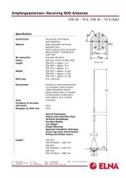
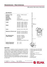
Specification<br />
Frequency ranges coil A: 250 - 320 kHz<br />
coil B: 320 - 390 kHz<br />
coil C: 390 - 450 kHz<br />
coil D: 450 - 580 kHz<br />
coil F: 180 - 290 kHz<br />
Max. RF-load 225 Watts CW<br />
Impedance MF resistance: 0.5 ... 4.0 Ohm<br />
capacitance: 200 ... 500 pF<br />
Polarization vertical<br />
Characteristic omnidirectional<br />
Construction self-supporting mast antenna<br />
RF injection methods 1. internal base injection<br />
2. external lead-in ... /E<br />
Material mast:<br />
glassfibre reinforced, polyester<br />
antenna base: G-AIMg3Si<br />
(seawater resistent aluminium)<br />
Colour grey<br />
Height <strong>STA</strong> <strong>150</strong> <strong>NDB</strong> … - 14.5 m<br />
<strong>STA</strong> 115 <strong>NDB</strong> ... - 11.5 m<br />
Weight <strong>STA</strong> <strong>150</strong> <strong>NDB</strong> approx. 80 kg<br />
<strong>STA</strong> 115 <strong>NDB</strong> approx. 50 kg<br />
Centre of gravity of surface 4.8 m<br />
Max. bending moment <strong>STA</strong> <strong>150</strong> <strong>NDB</strong> …<br />
1200 daNm (at <strong>150</strong> km/h wind<br />
and 8 m/s 2 acceleration)<br />
<strong>STA</strong> 115 <strong>NDB</strong> … 600 daNm<br />
Temperature - 40° … + 80° C<br />
Environment resistent to sea environment<br />
as met on board of seagoing<br />
vessels<br />
Icing isolation and foot impedance<br />
very little or not at all effected<br />
due to preventing protective<br />
measures<br />
Mould growth and microbes not effected<br />
Termites not effected<br />
<strong>STA</strong> <strong>150</strong> <strong>NDB</strong> (<strong>STA</strong> 115 <strong>NDB</strong>)
<strong>Funkfeuerantennen</strong> / <strong>Radio</strong> <strong>Beacon</strong> <strong>Antenna</strong><br />
Mounting Instructions<br />
The tilting device for the antenna is an indispensible accessory.<br />
It eases not only the first installation, but saves also avoidable<br />
costs later when the antenna must be laid down for maintenance<br />
(e.g. no cranes, large stages, etc.).<br />
The erection of the antenna can be done without a crane. The tilting<br />
plate of the tilting device may be opened as much as the<br />
spindle length permits in order to screw on the base end of the<br />
lower mast section US 80 PM. This mast part can be lifted easily<br />
be one man only. After being attached to the tilting plate the antenna<br />
may be lifted by the tilting device into a horizontal or other convenient<br />
position in order to fit the loading coil and to complete the<br />
top load assembly.<br />
The top load assembly may be installed in the same order as<br />
shown on picture 5. Special attention shall be paid to the retaining<br />
screws, pos. 5, hex nut 46 mm. They shall be screwed up with a<br />
torque wrench adjusted to 180 Nm.<br />
Unsafe fastening could have bad consequences.<br />
Base Injection (Internal Feeding)<br />
The connection between the internally fed antenna and supporting<br />
pipe with tilting device is made by a knife contact assembly (please,<br />
refer to picture 6). The single parts of such a base-injected<br />
equipment are readily equipped with the corresponding components<br />
of this knife contact assembly. Upon delivery of a combination<br />
of antenna with support as well as tilting flange the attached<br />
6 mm clamping cone does not have any function, but may be<br />
removed. Only in case of an installation of the base injected antenna<br />
without tilting device (with or without supporting pipe), this<br />
clamping cone has to be used, which means that the fitted knife<br />
contact must be dislodged. After the antenna has been assembled<br />
it should be erected slowly as the knife contact must be adjusted<br />
carefully until male and female parts meet properly. Only the male<br />
contact at the antenna shall be adjusted such that it fits the bottom<br />
of the female contact with 5 mm space. Attention shall be paid to<br />
it that the female contact at the supporting pipe may not be adjusted<br />
to avoid possible deformations. After the first adjustment the<br />
antenna shall be tilted two or three times in order to make sure the<br />
proper position of all components. When the contact assembly sits<br />
accurately, please, fix all counter screws.<br />
<strong>STA</strong> = Rod <strong>Antenna</strong> K = Tilt SSB = internal feeding <strong>NDB</strong> = Non Directional <strong>Radio</strong> <strong>Beacon</strong><br />
E = Receiving Rod <strong>Antenna</strong> TR = reinforced SSB/E = external feeding<br />
EAU = Transformer SE = Transmit <strong>Antenna</strong> PM/M = dark grey (similar to RAL 7000)<br />
<strong>STA</strong> <strong>150</strong> <strong>NDB</strong> (<strong>STA</strong> 115 <strong>NDB</strong>)<br />
Detail C<br />
Top Load Assembly<br />
Picture 5<br />
1 Lower mast section US 80 PM<br />
2 Loading coil<br />
3 Top rod <strong>STA</strong> 60 HV/2<br />
4 Top capacitance rod<br />
<strong>STA</strong> 30 D (4x)<br />
5 Hex nut 46 mm<br />
6 Capacitance ring<br />
7 Junction disk<br />
8 Holding nut<br />
9 O-Ring<br />
10 Hollow screw M 8<br />
11 Washer 8.2<br />
12 Locking screw<br />
13 Arresting pin
<strong>Funkfeuerantennen</strong> / <strong>Radio</strong> <strong>Beacon</strong> <strong>Antenna</strong><br />
Base Injection<br />
ELNA reserves the right to make changes in specifications<br />
without notice.<br />
June 2000<br />
Picture 6<br />
1 Tilting device K 8<br />
2 Spindle Assembly SP/G<br />
3 Supporting Pipe TR 12/K<br />
<strong>STA</strong> <strong>150</strong> <strong>NDB</strong> (<strong>STA</strong> 115 <strong>NDB</strong>)<br />
Section A-A<br />
Alternative
<strong>Funkfeuerantennen</strong> / <strong>Radio</strong> <strong>Beacon</strong> <strong>Antenna</strong><br />
External Feeding<br />
Please, choose the mounting place and the tilting direction carefully.<br />
Take care - that the antenna tilts into the approximate direction<br />
of the feeder wire, if possible. Otherwise, the feeder wire had to be<br />
detached before each tilting operation.<br />
The external feed assembly is shown on page 20 1.6. The nylon<br />
holding rope (pos. 4) with insulator (pos. 6) holds the feeder wire<br />
(pos. 7). The holding rope adjusts itself on the conical mast as the<br />
rope sling slips down until it fixes at its proper position approx. 2 m<br />
above the base.<br />
The feeder wire shall not be tightened too much. It shall hang loose,<br />
whereby a dip of 20 cm is allowed for a 4 m long wire. The wire<br />
shall slope downwards from the mast.<br />
Maintenance<br />
Although the antenna needs very little care, the operator should<br />
watch the antenna current from time to time. Unsteady antenna<br />
current often gives the first indication of undesired contamination<br />
of the antenna. Special attention shall be paid to the base area of<br />
the lower section US 80 PM and the loading coil. Both portions<br />
shall be washed with clear sweet water, if too much dirt has deposited.<br />
If really necessary, soft cleansers may be added to the water.<br />
Never paint the antenna or parts of it. Today’s industrial paints are<br />
based on metal containing colour pigments. Such paints will definitely<br />
reduce the antenna’s performance.<br />
<strong>STA</strong> = Rod <strong>Antenna</strong> K = Tilt SSB = internal feeding <strong>NDB</strong> = Non Directional <strong>Radio</strong> <strong>Beacon</strong><br />
E = Receiving Rod <strong>Antenna</strong> TR = reinforced SSB/E = external feeding<br />
EAU = Transformer SE = Transmit <strong>Antenna</strong> PM/M = dark grey (similar to RAL 7000)<br />
<strong>STA</strong> <strong>150</strong> <strong>NDB</strong> (<strong>STA</strong> 115 <strong>NDB</strong>)<br />
Picture 7
<strong>Funkfeuerantennen</strong> / <strong>Radio</strong> <strong>Beacon</strong> <strong>Antenna</strong><br />
Installation Proposal<br />
Base Injection<br />
ELNA reserves the right to make changes in specifications<br />
without notice.<br />
June 2000<br />
Picture 8<br />
<strong>STA</strong> <strong>150</strong> <strong>NDB</strong> (<strong>STA</strong> 115 <strong>NDB</strong>)
<strong>Funkfeuerantennen</strong> / <strong>Radio</strong> <strong>Beacon</strong> <strong>Antenna</strong><br />
Installation Proposal<br />
External Feeding<br />
Picture 9<br />
<strong>STA</strong> = Rod <strong>Antenna</strong> K = Tilt SSB = internal feeding <strong>NDB</strong> = Non Directional <strong>Radio</strong> <strong>Beacon</strong><br />
E = Receiving Rod <strong>Antenna</strong> TR = reinforced SSB/E = external feeding<br />
EAU = Transformer SE = Transmit <strong>Antenna</strong> PM/M = dark grey (similar to RAL 7000)<br />
<strong>STA</strong> <strong>150</strong> <strong>NDB</strong> (<strong>STA</strong> 115 <strong>NDB</strong>)<br />
Ground Network
<strong>Funkfeuerantennen</strong> / <strong>Radio</strong> <strong>Beacon</strong> <strong>Antenna</strong><br />
Concrete Basement for<br />
<strong>STA</strong> <strong>150</strong> <strong>NDB</strong><br />
ELNA reserves the right to make changes in specifications<br />
without notice.<br />
June 2000<br />
<strong>STA</strong> <strong>150</strong> <strong>NDB</strong> (<strong>STA</strong> 115 <strong>NDB</strong>)<br />
1 Foundation plate FP 8A<br />
2 Stone bolt M 16 x 200 - DIN 529 (8x)<br />
3 Counterpoise CP 18/15<br />
(18 radials at 15 m each)<br />
Tightening torque MA = 160 Nm
<strong>Funkfeuerantennen</strong> / <strong>Radio</strong> <strong>Beacon</strong> <strong>Antenna</strong><br />
<strong>STA</strong> <strong>150</strong> <strong>NDB</strong> …<br />
Standard Supplies<br />
A) Base Injected <strong>Antenna</strong> <strong>STA</strong> <strong>150</strong> <strong>NDB</strong>/ ... :<br />
1 collo (approx. 40 x 40 x 810 cm) = approx. 80 kilos =<br />
1 x lower section US 80 PM with<br />
1 x junction disk<br />
1 x top rod <strong>STA</strong> 60 HV/2<br />
4 x top capacitance rods <strong>STA</strong> 30 D<br />
1 x flat gasket<br />
1 wooden case (approx. 20 x 20 x 90 cm) = approx. 20 kilos =<br />
containing: 1 x loading coil<br />
1 x small material<br />
1 x description<br />
B) External <strong>Antenna</strong> <strong>STA</strong> <strong>150</strong> <strong>NDB</strong>/E/ … :<br />
1 collo (approx. 40 x 40 x 810 cm) = approx. 80 kilos =<br />
1 x lower section US 80 PM/E with<br />
1 x junction disk<br />
1 x top rod <strong>STA</strong> 60 HV/2<br />
4 x top capacitance rods <strong>STA</strong> 30 D<br />
1 x flat gasket.<br />
1 wooden case (approx. 20 x 20 x 90 cm) = approx. 20 kilos =<br />
containing: 1 x loading coil<br />
1 x holding rope with insulator<br />
1 x feeder wire 6 m (PTFE coated)<br />
1 x small material<br />
1 x description<br />
Optional Supplies<br />
Tilting Devices + Supporting Pipes<br />
Insulator Trunks STP 2500 resp. STP 3000 D<br />
Insulator P 502<br />
Insulator PB 500<br />
Insulator RHG 220<br />
Stand-Off Insulators ST 300 resp. ST 500<br />
Ground Networks<br />
<strong>STA</strong> = Rod <strong>Antenna</strong> K = Tilt SSB = internal feeding <strong>NDB</strong> = Non Directional <strong>Radio</strong> <strong>Beacon</strong><br />
E = Receiving Rod <strong>Antenna</strong> TR = reinforced SSB/E = external feeding<br />
EAU = Transformer SE = Transmit <strong>Antenna</strong> PM/M = dark grey (similar to RAL 7000)<br />
<strong>STA</strong> <strong>150</strong> <strong>NDB</strong> (<strong>STA</strong> 115 <strong>NDB</strong>)
<strong>Funkfeuerantennen</strong> / <strong>Radio</strong> <strong>Beacon</strong> <strong>Antenna</strong><br />
<strong>STA</strong> 115 <strong>NDB</strong> …<br />
Reduced Height Model <strong>STA</strong> 115 <strong>NDB</strong>/E/…<br />
(available on special request)<br />
The height of the antenna will be modified by using a lower mast<br />
section of 5 m only instead of the standard 8 m mast. The <strong>STA</strong> 115<br />
<strong>NDB</strong>/E is available with external feeder.<br />
It consists of: 1 x lower section US 50 PM/E (5 m long)<br />
1 x loading coil<br />
1 x top rod <strong>STA</strong> 60 HV/2<br />
4 x top capacitance rods <strong>STA</strong> 30 D<br />
It shall be mounted on the 1.5 m high support TR 15 R/E (resp.<br />
TR 15 R/E/B) with the tilting flange K 5/E.<br />
Further details can be taken from the data sheet <strong>STA</strong> 115<br />
C/MF/HF/E.<br />
Standard Supplies<br />
1 collo (approx. 30 x 30 x 590 cm) = approx. 40 kilos =<br />
1 x lower section US 50 PM/E with<br />
1 x junction disk<br />
1 x top rod <strong>STA</strong> 60 HV/2<br />
4 x top capacitance rods <strong>STA</strong> 30 D<br />
1 x flat gasket<br />
1 wooden case (approx. 20 x 20 x 90 cm) = approx. 20 kilos =<br />
1 x loading coil<br />
1 x holding rope with insulator<br />
1 x feeder wire 6 m (PTFE coated)<br />
1 x small material<br />
1 x description<br />
Optional Supply<br />
Please, refer to data sheet <strong>STA</strong> 115 C/MF/HF/E<br />
ELNA reserves the right to make changes in specifications<br />
without notice.<br />
June 2000<br />
<strong>STA</strong> <strong>150</strong> <strong>NDB</strong> (<strong>STA</strong> 115 <strong>NDB</strong>)
<strong>Funkfeuerantennen</strong> / <strong>Radio</strong> <strong>Beacon</strong> <strong>Antenna</strong><br />
External Feeding (Picture 4)<br />
Pos. Otv. Description Designation Remarks<br />
1 1 lower section US 80 PM/E external injection<br />
2 1 sealing cap 06-02-56-01-13<br />
3 1 lead-in insulator G 00-06-06-03-00<br />
4 1 holding rope D/26<br />
5 2 shackleAL63<br />
6 1 insulator RHG 220 cpl. with shackles<br />
7 1 litz wire O/41 PTFE coated<br />
8 1 flat gasket DI/27<br />
List of Components<br />
Top Load Assembly (Picture 5)<br />
Pos. Otv. Description Designation Remarks<br />
1 1 lower section US 80 PM or PM/E 8 m long<br />
2 1 loading coil A 250 - 320 kHz resp.<br />
B 320 - 390 kHz resp.<br />
C 390 - 450 kHz resp.<br />
D 450 - 580 kHz<br />
3 1 top rod <strong>STA</strong> 60 HV/2 6 m long (sectionalized)<br />
4 4 top capacitance rod <strong>STA</strong> 30 D 3 m long<br />
5 2 hex nut D/35 46 mm width<br />
6 1 top capacitance ring DK 4<br />
7 1 junction disk D/231<br />
8 1 locking nut D/34<br />
9 1 O-Ring DI/9<br />
10 8 hollow screw S 1/154<br />
11 8 spring washer S 1/58<br />
12 4 locking screw S 2/8<br />
13 2 arresting pin S 2/169<br />
<strong>STA</strong> = Rod <strong>Antenna</strong> K = Tilt SSB = internal feeding <strong>NDB</strong> = Non Directional <strong>Radio</strong> <strong>Beacon</strong><br />
E = Receiving Rod <strong>Antenna</strong> TR = reinforced SSB/E = external feeding<br />
EAU = Transformer SE = Transmit <strong>Antenna</strong> PM/M = dark grey (similar to RAL 7000)<br />
<strong>STA</strong> <strong>150</strong> <strong>NDB</strong> (<strong>STA</strong> 115 <strong>NDB</strong>)
<strong>Funkfeuerantennen</strong> / <strong>Radio</strong> <strong>Beacon</strong> <strong>Antenna</strong><br />
Spare Parts List<br />
Position Designation Order-Code<br />
1 <strong>STA</strong> 115 <strong>NDB</strong>/E/SA E 107-617<br />
1 <strong>STA</strong> 115 <strong>NDB</strong>/E/SB E 107-618<br />
1 <strong>STA</strong> 115 <strong>NDB</strong>/E/SC E 107-619<br />
1 <strong>STA</strong> 115 <strong>NDB</strong>/E/SD E 107-620<br />
1 <strong>STA</strong> 115 <strong>NDB</strong>/E/SF E 107-621<br />
1 <strong>STA</strong> <strong>150</strong> <strong>NDB</strong>/SA E 107-624<br />
1 <strong>STA</strong> <strong>150</strong> <strong>NDB</strong>/SB E 107-625<br />
1 <strong>STA</strong> <strong>150</strong> <strong>NDB</strong>/SC E 107-626<br />
1 <strong>STA</strong> <strong>150</strong> <strong>NDB</strong>/SD E 107-627<br />
1 <strong>STA</strong> <strong>150</strong> NDS/SF E 107-628<br />
1 <strong>STA</strong> <strong>150</strong> <strong>NDB</strong>/E/SA E 107-632<br />
1 <strong>STA</strong> <strong>150</strong> <strong>NDB</strong>/E/SB E 107-633<br />
1 <strong>STA</strong> <strong>150</strong> <strong>NDB</strong>/E/SC E 107-634<br />
1 <strong>STA</strong> <strong>150</strong> <strong>NDB</strong>/E/SD E 107-635<br />
1 <strong>STA</strong> <strong>150</strong> <strong>NDB</strong>/E/SF E 107-636<br />
2 Lower section US 80 PM/E E 107-552<br />
3 Lower mast section US 80 PM E 107-492<br />
4 Top rod <strong>STA</strong> 60 HV/2 E 107-082<br />
5 Top capacitance rod <strong>STA</strong> 30 D (4x) E 107-154<br />
ELNA reserves the right to make changes in specifications<br />
without notice.<br />
June 2000<br />
<strong>STA</strong> <strong>150</strong> <strong>NDB</strong> (<strong>STA</strong> 115 <strong>NDB</strong>)