Operating Mechanisms, Disconnect Switches, and Door ... - Square D
Operating Mechanisms, Disconnect Switches, and Door ... - Square D
Operating Mechanisms, Disconnect Switches, and Door ... - Square D

Create successful ePaper yourself
Turn your PDF publications into a flip-book with our unique Google optimized e-Paper software.
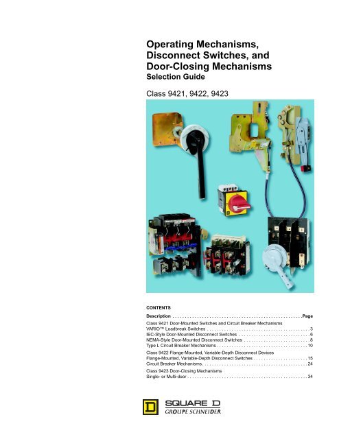
<strong>Operating</strong> <strong>Mechanisms</strong>,<br />
<strong>Disconnect</strong> <strong>Switches</strong>, <strong>and</strong><br />
<strong>Door</strong>-Closing <strong>Mechanisms</strong><br />
Selection Guide<br />
Class 9421, 9422, 9423<br />
CONTENTS<br />
Description . . . . . . . . . . . . . . . . . . . . . . . . . . . . . . . . . . . . . . . . . . . . . . . . . . . . .Page<br />
Class 9421 <strong>Door</strong>-Mounted <strong>Switches</strong> <strong>and</strong> Circuit Breaker <strong>Mechanisms</strong><br />
VARIO Loadbreak <strong>Switches</strong> . . . . . . . . . . . . . . . . . . . . . . . . . . . . . . . . . . . . . . . . . . 3<br />
IEC-Style <strong>Door</strong>-Mounted <strong>Disconnect</strong> <strong>Switches</strong> . . . . . . . . . . . . . . . . . . . . . . . . . . . . . 6<br />
NEMA-Style <strong>Door</strong>-Mounted <strong>Disconnect</strong> <strong>Switches</strong> . . . . . . . . . . . . . . . . . . . . . . . . . . . 8<br />
Type L Circuit Breaker <strong>Mechanisms</strong> . . . . . . . . . . . . . . . . . . . . . . . . . . . . . . . . . . . . . 10<br />
Class 9422 Flange-Mounted, Variable-Depth <strong>Disconnect</strong> Devices<br />
Flange-Mounted, Variable-Depth <strong>Disconnect</strong> <strong>Switches</strong> . . . . . . . . . . . . . . . . . . . . . . 15<br />
Circuit Breaker <strong>Mechanisms</strong>. . . . . . . . . . . . . . . . . . . . . . . . . . . . . . . . . . . . . . . . . . . 24<br />
Class 9423 <strong>Door</strong>-Closing <strong>Mechanisms</strong><br />
Single- or Multi-door . . . . . . . . . . . . . . . . . . . . . . . . . . . . . . . . . . . . . . . . . . . . . . . . . 34
2<br />
Note that all <strong>Square</strong> D switches <strong>and</strong> circuit breaker mechanisms are lockable in the OFF position, <strong>and</strong><br />
can be used to comply with OSHA requirements for an Energy Isolation Device.<br />
9422 Circuit Breaker<br />
Cable Operator<br />
9423 <strong>Door</strong>-Closing<br />
<strong>Mechanisms</strong><br />
How to Order<br />
To Order, Specify:<br />
1. Class Number<br />
2. Type Number<br />
— OR —<br />
1. Class Number<br />
2. Type Number of Switch Body<br />
3. Type Number of Shaft Extension<br />
4. Type Number of H<strong>and</strong>le Accessories<br />
5. Type Number of <strong>Door</strong> Interlock Plate<br />
6. Type Number of Any Desired Accessories<br />
9421L Circuit Breaker Mechanism<br />
NEMA-Style Rotary H<strong>and</strong>le<br />
<strong>Disconnect</strong> Switch<br />
NEMA-Style Flange H<strong>and</strong>le<br />
<strong>Disconnect</strong> Switch<br />
© 1997 <strong>Square</strong> D All Rights Reserved<br />
9422R Circuit Breaker Mechanism<br />
Loadbreak Switch<br />
IEC-Style<br />
<strong>Disconnect</strong> Switch<br />
Catalog Number<br />
Class Type<br />
9421 LN1<br />
12/97
.0.22<br />
Loadbreak Switch<br />
Non-Metallic Enclosure<br />
Metallic Enclosure<br />
Single-Hole Operator<br />
12/97<br />
VARIO Loadbreak <strong>Switches</strong><br />
© 1997 <strong>Square</strong> D All Rights Reserved<br />
Class 9421 Devices<br />
VARIO Loadbreak <strong>Switches</strong> act as enclosure disconnects when short circuit protection is provided<br />
upstream of the switch (if short circuit protection is not provided upstream, use Class 9421 Type N, Class<br />
9422 Type T, <strong>and</strong> D10 disconnect switches). Type V switches are UL Listed as manual motor controllers.<br />
Ampere Size<br />
Horsepower Ratings<br />
240 V 480 V 600 V<br />
Shaft Size<br />
3 Pole Switch Body<br />
Type<br />
Complete Switchq<br />
Type<br />
20 5.5 10 10 6mm V1 VCCF1<br />
25 7.5 15 20 6mm V2 VCCF2<br />
45 15.5 30 40 8mm V3 VCCF3<br />
63 20.5 40 50 8mm V4 VCCF4<br />
100 25.5 50 60 8mm V5 VCCF5<br />
115 30.5 60 75 8mm V6 VCCF6<br />
q Complete switch includes h<strong>and</strong>le operator, shaft, door interlock plate, <strong>and</strong> line terminal shroud.<br />
Non-Metallic Enclosures<br />
The VARIO Loadbreak Switch is also offered as an enclosed switch, which is made of corrosion resistant<br />
material suitable for IP55 environments. The 3-pole version makes the VARIO Loadbreak Switch ideal<br />
for manual motor control applications. They are compact, easy to wire <strong>and</strong> connect, <strong>and</strong> come undrilled<br />
to allow variable cable entry positions. Note that these enclosures do not pass the UL Burn Test, which<br />
means that these versions are not UL Listed.<br />
Ampere Size<br />
240V<br />
Horsepower Ratings<br />
480V 600V<br />
IP55-PVC 3-Pole<br />
Type<br />
20 5 10 10 VC1GU<br />
25 7.5 15 20 VC2GU<br />
45 15 30 40 VC3GU<br />
63 20 40 50 VC4GU<br />
100 25 50 60 VC5GU<br />
115 30 60 75 VC6GU<br />
Metallic Enclosures<br />
The V1<strong>and</strong> V2 come in metallic enclosures (NEMA Type 1, 4, 4X, <strong>and</strong> 12). The NEMA Type 1 is supplied<br />
with conduit knockouts top <strong>and</strong> bottom. A VZ7 auxiliary contact can be factory installed in these metallic<br />
enclosures by adding Form X11 to the catalog number. A VZ20 auxiliary contact can be factory installed<br />
in these enclosures by adding Form X20 to the catalog number. Two V27 auxiliary contacts may be factory<br />
installed by adding Form X22 (2 N.O. <strong>and</strong> 2 N.C.).<br />
Ampere Size<br />
Horsepower Ratings<br />
240V 480V 600V<br />
NEMA Type 1<br />
Type<br />
NEMA Type 12<br />
Type<br />
NEMA Type 4/4Xp<br />
Type<br />
20 5 10 10 V1G30 V1A30 V1W30<br />
25 7.5 15 20 V2G30 V2A30 V2W30<br />
p For indoor use only. The NEMA 4/4X enclosure is made of #304 stainless steel with 3/4 in T&B stainless steel hubs on the top <strong>and</strong> bottom.<br />
H<strong>and</strong>le Operators<br />
Single-Hole Operator (22.5 or 30.5 mm diameters)<br />
Description Type<br />
<strong>Square</strong> 60 x 60<br />
Protection IP65<br />
(up to 3 padlocks)<br />
Drilling dimensions are shown on the next page.<br />
H<strong>and</strong>le Operators Gasket for<br />
Red Bezel<br />
Yellow H<strong>and</strong>le<br />
Black Bezel<br />
<strong>and</strong> H<strong>and</strong>le<br />
IP65 Protection<br />
(5 per package)<br />
Black Legend<br />
Silver Plate<br />
Type Type Type Type<br />
V1, V2 (6mm shaft) KCD1PZ KAD1PZ KZ66 KZ15<br />
Open Product Metallic Enclosure<br />
File E164864<br />
CCN: NLRV<br />
File LR81630<br />
Class 3211-05<br />
File E42243<br />
CCN: NLRV<br />
File LR25490<br />
Class 3211-05<br />
3
Class 9421 Devices<br />
in (mm)<br />
0.51 (13) 0.22 (5.5) 0.51 (13)<br />
4<br />
1.89 (48)<br />
Four-Hole Operator<br />
(All except KBF3PZ<br />
<strong>and</strong> KDF3PZ)<br />
1.73<br />
(44)<br />
in (mm)<br />
1.73<br />
(44)<br />
b<br />
2.68 (68)<br />
1.89 (48) in (mm) 2.68 (68)<br />
Four-Hole 60x60<br />
Four-Hole 90x90<br />
Drilling Dimensions Drilling Dimensions<br />
in (mm)<br />
.06-.24 (1.5-6)<br />
Four-Hole Operator<br />
(KBF3PZ or KDF3PZ)<br />
Rear/Panel-Mounting Switch Body<br />
0.12 (3.0)<br />
0.89<br />
(22.5)<br />
a<br />
0.5<br />
(12.7)<br />
Single-Hole<br />
Drilling Dimensions<br />
.06-.24 (1.5-6)<br />
a b<br />
Single- <strong>and</strong> Four-Hole Mounting Dimensions<br />
a<br />
c<br />
b<br />
c<br />
dia. d<br />
Main Pole <strong>and</strong> Auxiliary<br />
Contact Module Dimensions<br />
c<br />
Four-Hole Operator<br />
Description Type<br />
<strong>Square</strong> 60 x 60<br />
Protection IP65<br />
(up to three<br />
padlocks)<br />
<strong>Square</strong> 90 x 90<br />
Protection IP65<br />
(up to three<br />
padlocks)<br />
<strong>Square</strong> 90 x 90<br />
Protection IP65<br />
V1, V2<br />
(6mm shaft)<br />
V3, V4<br />
(8mm shaft)<br />
V3-V6<br />
(8mm shaft)<br />
V3-V6<br />
(8mm shaft)<br />
Dimensions for VARIO Loadbreak <strong>Switches</strong><br />
Rear/Panel-Mounting Switch Body Dimensions<br />
Type<br />
V1 to V2<br />
V3 to V4<br />
V5 to V6<br />
Shaft<br />
Extension<br />
VZ17<br />
VZ30<br />
VZ18<br />
VZ31<br />
VZ18<br />
VZ31<br />
c The door interlock plate included with VCCF has the same drilling as the h<strong>and</strong>le operators.<br />
Single- <strong>and</strong> Four-Hole Mounting Dimensions<br />
Type<br />
V1 to V2t<br />
V1 to V2<br />
V3 to V4<br />
V5 to V6<br />
t Dimensions for single-hole mounting.<br />
Main Pole Module Dimensions<br />
Auxiliary Contact Module Dimensions<br />
© 1997 <strong>Square</strong> D All Rights Reserved<br />
H<strong>and</strong>le Operators<br />
Red Bezel<br />
Yellow<br />
H<strong>and</strong>le<br />
Black<br />
Bezel<br />
<strong>and</strong><br />
H<strong>and</strong>le<br />
Gasket for<br />
IP65 Protection<br />
(5 per package)<br />
Black Legend<br />
Silver Plate<br />
Type Type Type Type<br />
KCF1PZ KAF1PZ<br />
KCF2PZ KAF2PZ KZ66 KZ15<br />
KCF3PZ KAF3PZ KZ67 –<br />
KDF3PZ KBF3PZ KZ67 –<br />
Dimensions – inches (millimeters)<br />
a b c d<br />
5.5-13.0 (140-330)<br />
5.5-16.9 (140-430)<br />
5.5-12.6 (140-320)<br />
5.5-16.5 (140-420)<br />
6.5-13.8 (165-350)<br />
6.5-17.7 (165-450)<br />
0.60 (15) 2.4 (60) 0.17 (4.2)<br />
0.79 (20) 2.4 (60) 0.20 (5.2)<br />
1.20 (30) 3.9 (100) 0.28 (7.0)<br />
Dimensions – inches (millimeters) Weight<br />
Approx. lbs.<br />
a b c<br />
2.83 (72)<br />
2.36 (60)<br />
2.56 (65)<br />
3.54 (90)<br />
2.17 (55)<br />
2.17 (55)<br />
2.36 (60)<br />
3.54 (90)<br />
2.91 (74)<br />
2.91 (74)<br />
3.27 (83)<br />
4.92 (125)<br />
0.44<br />
0.44<br />
1.10<br />
2.00<br />
Type<br />
Dimensions – inches (millimeters)<br />
a b c<br />
Weight<br />
Approx. lbs.<br />
VZ1 to VZ2 0.63 (16) 2.9 (74) 1.38 (35) 0.10<br />
VZ3 to VZ4 0.79 (20) 3.3 (83) 1.80 (46) 0.22<br />
Type<br />
Dimensions – inches (millimeters)<br />
a b c<br />
Weight<br />
Approx. lbs.<br />
V27 0.79 (20) 2.56 (65) 1.91 (48.5) 0.11<br />
VZ20 0.79 (20) 2.56 (65) 1.91 (48.5) 0.11<br />
12/97
6 7/8<br />
174.63<br />
Terminal Shroud<br />
for Main Switch<br />
VZ8<br />
O 6,2<br />
e<br />
b<br />
12/97<br />
3.0<br />
76.2<br />
Shaft Extension Kit<br />
Add-On Contact Modules<br />
d a<br />
Non-Metallic Enclosed Switch<br />
5 5/8<br />
142.88<br />
5 3/8<br />
136.53<br />
Terminal Shroud<br />
for Auxiliary Contact<br />
VZ29<br />
c<br />
f<br />
4 1/4<br />
107.95<br />
5 7/8<br />
149.23<br />
Metallic Enclosed Switch: NEMA Type 1 (V1G30, V2G30)<br />
Accessories for VARIO Loadbreak <strong>Switches</strong><br />
Shaft Extension <strong>and</strong> <strong>Door</strong> Interlock<br />
For<br />
Switch Type<br />
Accessories<br />
For<br />
Switch Type<br />
Add-On Contact Modules<br />
q Early Break, Late Make.<br />
© 1997 <strong>Square</strong> D All Rights Reserved<br />
Maximum<br />
Panel Depth<br />
Class 9421 Devices<br />
Dimensions for Enclosed VARIO Loadbreak <strong>Switches</strong><br />
Non-Metallic Enclosed Switch Dimensions<br />
Metallic Enclosed Switch Dimensions<br />
Shaft<br />
Extension Kit<br />
<strong>Door</strong><br />
Interlock Plate<br />
V1, V2 13.0" VZ17 KZ32<br />
V3, V4 12.6" VZ18 KZ74<br />
V5, V6 13.8" VZ18 KZ74<br />
V1, V2 16.9" VZ30 KZ32<br />
V3, V4 16.5" VZ31 KZ74<br />
V5, V6 17.7" VZ31 KZ74<br />
Line Side<br />
Terminal Shroud for<br />
Main Switch<br />
Terminal Shroud for<br />
Main Pole Module<br />
Terminal Shroud for<br />
Auxiliary Contact<br />
V1, V2 VZ8 VZ26 VZ29<br />
V3, V4 VZ9 VZ27 VZ29<br />
V5, V6 VZ10 VZ28 VZ29<br />
For<br />
Main Pole<br />
Auxiliary Contacts<br />
Switch Type<br />
Module<br />
1 N.O. & 1 N.C. q 2 N.O.<br />
V1 VZ1 VZ7 VZ20<br />
V2 VZ2 VZ7 VZ20<br />
V3 VZ3 VZ7 VZ20<br />
V4 VZ4 VZ7 VZ20<br />
V5 — VZ7 VZ20<br />
V6 — VZ7 VZ20<br />
Type<br />
No. of<br />
Poles<br />
VC1GU - VC2GU 3<br />
VC3GU - VC4GU 3<br />
VC5GU - VC6GU 3<br />
7 3/8<br />
187.33<br />
3.0<br />
76.2<br />
5 1/2<br />
139.7<br />
Dimensions – inches (millimeters)<br />
a b c d e f<br />
6.7<br />
(170)<br />
6.7<br />
(170)<br />
11.0<br />
(280)<br />
6 3/4<br />
171.45<br />
4.1<br />
(105)<br />
5.3<br />
(135)<br />
8.6<br />
(220)<br />
3.2<br />
(82)<br />
3.3<br />
(85)<br />
5.0<br />
(126)<br />
4 1/2<br />
114.3<br />
6 1/4<br />
158.75<br />
NEMA Type 4, 4X, 12<br />
(V1W30, V2W30, V1A30, V2A30)<br />
4.8<br />
(122)<br />
5.1<br />
130)<br />
7.9<br />
(201)<br />
2.1<br />
(53)<br />
3.7<br />
(95)<br />
7.5<br />
(190)<br />
5.0<br />
(128)<br />
5.2<br />
(131)<br />
8.0<br />
(203)<br />
5
Class 9421 Devices<br />
6<br />
Class 9421<br />
<strong>Disconnect</strong> Switch<br />
Auxiliary<br />
Contact<br />
H<strong>and</strong>le<br />
Terminal Shields<br />
<strong>and</strong> Fuse Covers<br />
Auxiliary Components<br />
File E14839<br />
CCN: NKCR2<br />
File CR75721<br />
Class 3211 02<br />
Class 9421<br />
IEC-Style <strong>Door</strong>-Mounted <strong>Disconnect</strong> <strong>Switches</strong> (Type N)<br />
The 9421 Type N is an IEC-style door-mounted disconnect switch with onboard fusing for Class CC <strong>and</strong><br />
Class J fuses. The switch is UL Listed <strong>and</strong> CSA certified, <strong>and</strong> provides service entrance spacing, 100KA<br />
withst<strong>and</strong>ability <strong>and</strong> Type 2 coordinated protection when used with <strong>Square</strong> D <strong>and</strong> Telemecanique starters<br />
in accordance with fuse selection tables.<br />
Each installation will require a disconnect switch, h<strong>and</strong>le, <strong>and</strong> shaft.<br />
Class 9421 <strong>Disconnect</strong> <strong>Switches</strong><br />
<strong>Disconnect</strong><br />
Switch Size<br />
30A<br />
60A<br />
H<strong>and</strong>les<br />
<strong>Disconnect</strong><br />
Switch Size<br />
1 Phase AC<br />
Maximum Horsepower Ratings<br />
3 Phase AC DC<br />
115V 230V 200V 230V 460V 575V 125V 250V<br />
File E152727 File LR75721<br />
CCN: WJA2 Class 3211 02<br />
Fuse<br />
Selection<br />
30A, 60A All<br />
Terminal Shields <strong>and</strong> Fuse Covers<br />
<strong>Disconnect</strong><br />
Switch Size<br />
30A<br />
60A<br />
Outline Dimensions <strong>and</strong> General Location Information for 30 Amp Type N <strong>Disconnect</strong> <strong>Switches</strong><br />
© 1997 <strong>Square</strong> D All Rights Reserved<br />
Fuse Selection<br />
12/97<br />
Switch<br />
2 3 7.5 7.5 15 20 3 5 Unfused NC1<br />
.75 2 5 5 10 10 2 3 30A Class CC NC2<br />
2 3 7.5 7.5 15 20 3 5 30A Class J NC3<br />
3 10 15 15 30 50 5 10 Unfused ND1<br />
3 10 15 15 30 50 5 10 60A Class J ND3<br />
H<strong>and</strong>le<br />
Color<br />
H<strong>and</strong>le<br />
Selection<br />
NEMA<br />
Type<br />
H<strong>and</strong>le<br />
Kit<br />
Type<br />
Red/Yellow 1/12/4/4X NW2<br />
Black 1/12/4/4X NW2B<br />
Type<br />
Terminal Shieldp NTS30<br />
CC Fuse Cover t NCF30<br />
J Fuse Cover NJF30<br />
Terminal Shieldp NTS60<br />
J Fuse Covert NJF60<br />
Auxiliary Contact Shielda NXSH<br />
p Terminal shield for line or load side.<br />
t 30A CC fuse cover <strong>and</strong> 60A J fuse cover are also used for non-fusible<br />
applications.<br />
a 2 per package<br />
LINE TERMINALS<br />
0.63<br />
(16)<br />
TYP. PER CONTACT<br />
UP TO FOUR AUXILIARY<br />
BLOCKS MAY BE FITTED<br />
MUST BE INNER<br />
AUXILIARY CONTACT<br />
LOAD TERMINALS<br />
4.33 (110)<br />
3.82 (97)<br />
LINE TERMINAL<br />
SHIELD STANDARD<br />
LOAD TERMINAL<br />
SHIELD OPTIONAL<br />
inches<br />
(millimeters)<br />
4.45<br />
(113) 4.65<br />
(118)<br />
OPERATING SHAFT & COUPLING<br />
Shafts <strong>and</strong> Shorting Links<br />
<strong>Disconnect</strong><br />
Switch Size<br />
Enclosure<br />
Depth (max.)<br />
Auxiliary Contacts<br />
TERMINAL<br />
CONNECTIONS<br />
3.73 TYPE NC1, NC2<br />
(95) with fuse cover<br />
5.70 TYPE NC3<br />
(145) with fuse cover<br />
Shaft Length<br />
1.27<br />
(32)<br />
Type<br />
Shaft Kit<br />
Type<br />
30A, 60A<br />
10"<br />
18"<br />
166mm<br />
360mm<br />
NS16<br />
NS36<br />
Shorting<br />
Linksq<br />
30A NSL30<br />
60A NSL60<br />
q 3 per package; replacement for 9421 NC1 & 9421 ND1<br />
<strong>Disconnect</strong><br />
Switch Size<br />
Auxiliary<br />
Contact<br />
Kit<br />
Type<br />
SPDT N.O. Inner NAX10<br />
30A, 60A<br />
SPDT<br />
DPDT<br />
N.O.<br />
2 N.O.<br />
Outer<br />
Inner<br />
NBX10<br />
NAX20<br />
DPDT 2 N.O. Outer NBX20<br />
NOTE: Each installation requires a disconnect switch, h<strong>and</strong>le, <strong>and</strong><br />
shaft. Further, the first auxiliary contact block that is used must be an<br />
inner block (maximum is 1 inner <strong>and</strong> 3 outer blocks).
120°<br />
Front Cover<br />
12/97<br />
1.34<br />
(34)<br />
120°<br />
Drilling Dimensions for 9421 NW2/NW2B<br />
9421 30 Amp NC<br />
Mounting Dimensions<br />
9421 60 Amp ND<br />
Mounting Dimensions<br />
1.34<br />
(34)<br />
1 Hole<br />
1.375 (35) diameter<br />
3.50<br />
89 MIN.<br />
4.25<br />
108 MINIMUM<br />
inches<br />
(millimeters)<br />
3 Holes<br />
1.36 (34.5) diameter<br />
0.77<br />
(19.4)<br />
1.55<br />
(39.4)<br />
6.75<br />
171 MINIMUM<br />
3.34 mtg<br />
85<br />
0.30<br />
7.62<br />
Outline Dimensions <strong>and</strong> General Location Information<br />
for 60 Amp Type N <strong>Disconnect</strong> <strong>Switches</strong><br />
LINE TERMINALS<br />
TYP. PER CONTACT<br />
0.63<br />
(16)<br />
UP TO FOUR AUXILIARY<br />
BLOCKS MAY BE FITTED<br />
MUST BE INNER<br />
AUXILIARY CONTACT<br />
1.62<br />
41<br />
3.23<br />
82<br />
© 1997 <strong>Square</strong> D All Rights Reserved<br />
5.62 (143)<br />
5.14 (131)<br />
LINE TERMINAL SHIELD STANDARD<br />
LOAD TERMINAL SHIELD OPTIONAL<br />
5.36<br />
(136)<br />
LOAD TERMINALS OPERATING SHAFT & COUPLING<br />
1.75<br />
45 MINIMUM (SEE NOTE )<br />
DOOR<br />
FLANGE<br />
mtg<br />
9.75<br />
248 MINIMUM<br />
DIMENSION Y<br />
QUANTITY (2) MOUNTING SCREWS #8-32 X 2 / M4 X 50MM (PROVIDED WITH SWITCH)<br />
MUST BE INNER AUXILIARY CONTACT<br />
8.00<br />
203<br />
MINIMUM<br />
4.72 mtg<br />
120<br />
0.40<br />
10<br />
1.75<br />
(SEE NOTE )<br />
45 MINIMUM<br />
1.97<br />
50<br />
3.94<br />
100<br />
DOOR<br />
FLANGE<br />
9.75<br />
248 MINIMUM<br />
QUANTITY (4) MOUNTING SCREWS #8-32 X 2 / M4 X 50MM (PROVIDED WITH SWITCH)<br />
MUST BE INNER AUXILIARY CONTACT<br />
mtg<br />
6.10<br />
(155)<br />
Class 9421 Devices<br />
inches<br />
(millimeters)<br />
FOR EXTENSION SHAFT<br />
MODIFICATION SEE<br />
FIGURE 3<br />
DUAL DIMENSIONS<br />
IN<br />
MM<br />
TERMINAL CONNECTIONS<br />
4.87<br />
(124)<br />
5.06<br />
(128)<br />
WHEN ADDING EXTENSION SHAFT<br />
USE BOTH COTTER PIN AND<br />
M3 X 8MM LONG SOCKET HEAD<br />
CAP SCREW PROVIDED WITH DEVICE.<br />
TORQUE 2NM (18 LB. IN.)<br />
TYPE ND 1, ND 3<br />
With Fuse Cover<br />
1.27<br />
(32)<br />
DISTANCE FROM OUTSIDE OF DOOR TO SWITCH MOUNTING SURFACE.<br />
DIMENSION Y<br />
17.87/445 MAXIMUM WHEN USING THE TYPE NS36 SHAFT<br />
10.75/273 MAXIMUM WHEN USING THE TYPE NS16 SHAFT<br />
6.11/155 MINIMUM WITH CUT SHAFT<br />
DISTANCE FROM OUTSIDE OF DOOR TO SWITCH MOUNTING SURFACE.<br />
17.87/445 MAXIMUM WHEN USING THE TYPE NS36 SHAFT<br />
10.75/273 MAXIMUM WHEN USING THE TYPE NS16 SHAFT<br />
6.11/155 MINIMUM WITH CUT SHAFT<br />
WHEN ADDING EXTENSION SHAFT<br />
USE BOTH COTTER PIN AND<br />
M3 X 8MM LONG SOCKET HEAD<br />
CAP SCREW PROVIDED WITH DEVICE.<br />
TORQUE 2NM (18 LB. IN.)<br />
FOR EXTENSION SHAFT<br />
MODIFICATION SEE<br />
FIGURE 3<br />
DUAL DIMENSIONS IN<br />
MM<br />
7
Class 9421 Devices<br />
8<br />
Switch<br />
File E52369<br />
CCN: WHTY2<br />
File LR15705<br />
Class 4652 04<br />
Auxiliary Switch<br />
File E78403<br />
CCN: NKCR<br />
H<strong>and</strong>le<br />
File E52369<br />
CCN: WHTY2<br />
NEMA-Style <strong>Door</strong>-Mounted <strong>Disconnect</strong> <strong>Switches</strong> (D10)<br />
A complete installation includes a D10 disconnect switch, D11 h<strong>and</strong>le operator, <strong>and</strong> D12 fuse clip kit.<br />
The D10 accepts Class H, K, J, or R fuses — or can be used for non-fusible applications. The D10 disconnect<br />
switch is operated by a cast metal h<strong>and</strong>le operator that is lockable in the OFF position <strong>and</strong> defeatable<br />
in the ON position. Other features of the D10 disconnect switch are:<br />
High I 2 T rating – This switch meets automotive <strong>and</strong> heavy-industry requirements.<br />
Longer contact life – Quick-make, quick-break, cam-trip, <strong>and</strong> spring-loaded action throws the<br />
switch into the ON position under pressure. This provides a quick-break when switching to the<br />
OFF position. The double-break contact principle also assures longer life <strong>and</strong> exceptional interrupting<br />
capacity.<br />
Visible contact indication – Clear ON <strong>and</strong> OFF markings plus actual contact positions are both<br />
visible through pole “windows.”<br />
Fuse-mounting flexibility – Fuse clips are mounted on top of the switch, providing a compact<br />
unit. Interchangeable fuse-clip kits are available for quick adaptation to other ratings.<br />
Dead-front construction – When the switch is in the OFF position, all visible current-carrying<br />
parts are de-energized, thus providing additional safety for maintenance electricians.<br />
Auxiliary interlocks – One- or two-pole interlocks can be added to the disconnect switch when<br />
required.<br />
<strong>Disconnect</strong> <strong>Switches</strong><br />
(Without Fuse Clips or Shorting Straps)<br />
600V – Without Service Entrance Rating<br />
Starter<br />
NEMA<br />
Type<br />
Size<br />
0 - 1<br />
2<br />
3<br />
4<br />
Switch<br />
Rating<br />
Amperes<br />
30<br />
60<br />
100<br />
200<br />
0 - 1 30 5 10 20<br />
2 60 10 20 40<br />
3 100 15 30 60<br />
4 200 25 50 100<br />
j Non-fused rating; with fuses, depends on fuse size.<br />
Rotary H<strong>and</strong>le <strong>Operating</strong> Mechanism<br />
Auxiliary Electrical Interlock<br />
(for mounting on 30A – 200A switchk)<br />
k One block per switch.<br />
Max. Horsepower Ratingj<br />
120V<br />
5<br />
10<br />
15<br />
25<br />
200-<br />
240V<br />
10<br />
20<br />
30<br />
50<br />
600V – With Service Entrance Rating<br />
Starter<br />
NEMA<br />
Type<br />
Size<br />
Switch<br />
Rating<br />
Amperes<br />
480V 600V<br />
20<br />
40<br />
60<br />
100<br />
25<br />
50<br />
75<br />
100<br />
Max. Horsepower Rating j<br />
120V<br />
200-<br />
240V<br />
480V 600V<br />
Rotary H<strong>and</strong>le Operator Kits – <strong>Door</strong> Mounting<br />
NEMA Type 1, 3, 3R, 4, 12<br />
Description<br />
Variable Depth<br />
Rotary Operator<br />
Amp<br />
Rating<br />
30, 60<br />
100,<br />
200<br />
Block Description<br />
(With Switch Contacts Open)<br />
Enclosure Interior<br />
Depth - Inches<br />
25<br />
50<br />
75<br />
100<br />
Catalog<br />
Number<br />
D10S1<br />
D10S2<br />
D10S3<br />
D10S4<br />
Catalog<br />
Number<br />
D10S1H<br />
D10S2H<br />
D10S3H<br />
D10S4H<br />
For MC<br />
<strong>Switches</strong><br />
Catalog<br />
Number<br />
5 5 ⁄ 8 - 6 D11SF4<br />
6 - 10<br />
10 - 16<br />
1 Normally Open<br />
1 Normally Closed<br />
1 Normally Open <strong>and</strong> 1 Normally Closed<br />
2 Normally Open<br />
2 Normally Open <strong>and</strong> 2 Normally Closed<br />
D11SF10<br />
D11SF16<br />
Catalog<br />
Number<br />
D11N0<br />
D11NC<br />
D11N0C<br />
D11N00<br />
D11N0C2<br />
© 1997 <strong>Square</strong> D All Rights Reserved<br />
Fuse Clip Kits<br />
D10<br />
Switch<br />
Size<br />
30 A<br />
60 A<br />
100 A<br />
200 A<br />
Fuse-Clip Ratingq<br />
Amperes AC Volts Type<br />
0 - 30<br />
0 - 30<br />
0 - 30<br />
0 - 30<br />
0 - 30<br />
31 - 60<br />
31 - 60<br />
31 - 60<br />
31 - 60<br />
61 - 100<br />
0 - 30<br />
0 - 30<br />
0 - 30<br />
31 - 60<br />
31 - 60<br />
31 - 60<br />
31 - 60<br />
31 - 60<br />
61 - 100<br />
61 - 100<br />
61 - 100<br />
31 - 60<br />
31 - 60<br />
61 - 100<br />
61 - 100<br />
61 - 100<br />
61 - 100<br />
61 - 100<br />
101 - 200<br />
101 - 200<br />
101 - 200<br />
201 - 400<br />
201 - 400<br />
61 - 100<br />
101 - 200<br />
101 - 200<br />
101 - 200<br />
101 - 200<br />
101 - 200<br />
201 - 400<br />
201 - 400<br />
201 - 400<br />
201 - 400<br />
201 - 400<br />
Catalog<br />
Number<br />
No Fuse D12CO1<br />
250<br />
250<br />
600<br />
600<br />
600<br />
250<br />
600<br />
600<br />
600<br />
250<br />
H, K<br />
R<br />
H, K<br />
R<br />
J<br />
H, K<br />
H, K<br />
R<br />
J<br />
H, K<br />
D12C21<br />
D12CR21<br />
D12C61<br />
D12CR61<br />
D12CJ1<br />
D12C22<br />
D12C62<br />
D12CR62<br />
D12CJ2<br />
D12C23<br />
No Fuse D12D02<br />
250<br />
600<br />
600<br />
250<br />
250<br />
600<br />
600<br />
600<br />
250<br />
600<br />
600<br />
R<br />
H, K<br />
R<br />
H, K<br />
R<br />
H, K<br />
R<br />
J<br />
H, K<br />
H, K<br />
J<br />
D12DR21<br />
D12D61<br />
D12DR61<br />
D12D22<br />
D12DR22<br />
D12D62<br />
D12DR62<br />
D12DJ2<br />
D12D23<br />
D12D63✫<br />
D12DJ3<br />
No Fuse D12E03<br />
250<br />
600<br />
250<br />
250<br />
600<br />
600<br />
600<br />
250<br />
600<br />
600<br />
250<br />
600<br />
H, K<br />
H, K<br />
H, K<br />
R<br />
H, K<br />
R<br />
J<br />
H, K<br />
H, K<br />
J<br />
H, K<br />
J<br />
D12E22<br />
D12E62<br />
D12E23<br />
D12ER23<br />
D12E63<br />
D12ER63<br />
D12EJ3<br />
D12F24<br />
D12F64<br />
D12FJ4<br />
D12F25b<br />
D12FJ5b<br />
No Fuse D12F04<br />
600<br />
250<br />
250<br />
600<br />
600<br />
600<br />
250<br />
250<br />
600<br />
600<br />
600<br />
H, K<br />
H, K<br />
R<br />
H, K<br />
R<br />
J<br />
H, K<br />
H, K<br />
H, K<br />
R<br />
J<br />
D12F63<br />
D12F24<br />
D12FR24<br />
D12F64<br />
D12FR64<br />
D12FJ4<br />
D12F25b<br />
D12FR25b<br />
D12F65b<br />
D12FR65b<br />
D12FJ5b<br />
q Continuous current should not exceed switch rating (size). Fuse clip kits<br />
should be sized to accommodate inrush.<br />
b Cannot be used with service entrance rated switch.<br />
12/97
Rotary H<strong>and</strong>le Dimensions (in inches)<br />
B<br />
A E<br />
12/97<br />
F<br />
LINE SHIELD<br />
H<br />
G<br />
CENTERLINE<br />
OF SWITCH<br />
OPERATING<br />
SHAFT<br />
I<br />
J<br />
D<br />
C<br />
Switch Dimensional Sketch<br />
MC Switch Interrupting <strong>and</strong> Withst<strong>and</strong>ability Ratings<br />
NOTE: These switches are for motor circuit applications.<br />
Lug Data<br />
Switch Rating<br />
Amperes<br />
Switch<br />
Rating<br />
30<br />
Switch Dimensions (in inches)<br />
j Maximum depth with largest fuse.<br />
c Depth including insulating barrier on service entrance switches<br />
© 1997 <strong>Square</strong> D All Rights Reserved<br />
Interrupting Rating Amperes<br />
Symmetrical<br />
600 Vac, 3 PH<br />
Class 9421 Devices<br />
Withst<strong>and</strong>ability I 2 T<br />
(Amperes 2 seconds)<br />
30 1,200 .38 x 106 60 1,800 1.28 x 10 6<br />
100 2.000 2.62 x 10 6<br />
200 3,600 5.25 x 10⁶ Number<br />
Per Pole<br />
Wire Range Wire Type<br />
#14 - #8 Cu<br />
60<br />
100<br />
1<br />
#14 - #4<br />
#14 - #1/0<br />
Cu<br />
Al - Cu<br />
200 #6 - 250 MCM Al - Cu<br />
Switch Length Width Mounting Hole Dimensions Depth<br />
Size A B C D E F G H I J Kjlc 30 7 5 ⁄ 16 4 15 ⁄ 32 5 7 ⁄ 8 3 15 ⁄ 32 6 3 15 ⁄ 32 1 7 ⁄ 8<br />
13<br />
⁄32 5 7 ⁄ 16 31 / 4 4 3 ⁄ 32 4 11 ⁄ 32<br />
60 7 5 ⁄ 16 4 15 ⁄ 32 5 7 ⁄ 8 3 15 ⁄ 32 6 3 15 ⁄ 32 1 7 ⁄ 8<br />
13<br />
⁄32 5 7 ⁄ 16 31 / 4 4 11 ⁄ 32 4 11 ⁄ 32<br />
100 927 ⁄ 32 511 ⁄ 32 83 ⁄ 16 45 ⁄ 8 513 ⁄ 16 313 ⁄ 16 211 ⁄ 16<br />
51<br />
⁄64 75 ⁄ 16 43 ⁄ 16 523 ⁄ 32 427 ⁄ 32<br />
200 12 3 ⁄ 16 7 7 ⁄ 32 8 3 ⁄ 16 4 5 ⁄ 8 5 13 ⁄ 16 3 13 ⁄ 16 2 11 ⁄ 16<br />
51<br />
⁄64 7 5 ⁄ 16 4 3 ⁄ 16 5 23 ⁄ 32 4 27 ⁄ 32<br />
9
Class 9421 Devices<br />
10<br />
3” H<strong>and</strong>le<br />
Assembly<br />
St<strong>and</strong>ard H<strong>and</strong>le<br />
Assembly<br />
<strong>Operating</strong> Mechanism<br />
(includes lockout)<br />
IEC-Style H<strong>and</strong>le<br />
(for use with<br />
9421LG8, see page 11)<br />
File E62922<br />
CCN: DIHS2<br />
Class 9421 Type L Circuit Breaker <strong>Mechanisms</strong><br />
Type L door-mounted, variable-depth operating mechanisms feature heavy duty, all metal construction<br />
with trip indication. All can be padlocked in the “OFF” position when the enclosure door is open. Further,<br />
the h<strong>and</strong>le assemblies can be locked “OFF” with up to three padlocks, which also locks the door closed.<br />
(The 3" h<strong>and</strong>le accepts one padlock.)<br />
Complete Kits<br />
Complete kits are rated for NEMA Type 1, 3R <strong>and</strong> 12 enclosures, <strong>and</strong> a door-drilling template is supplied to<br />
ease installation. They include a h<strong>and</strong>le assembly, operating mechanism, <strong>and</strong> shaft assembly.<br />
Complete Kit<br />
Does Not Include Circuit Breaker.<br />
Circuit Breaker<br />
or Interrupter Type<br />
Use With<br />
Number<br />
of Poles<br />
Frame<br />
Size (A)<br />
q Mounting depth measured from circuit breaker mounting surface (control panel) to outside of enclosure door in inches.<br />
j Types LT1, LT4, LX1, <strong>and</strong> LX4 include an 8” h<strong>and</strong>le rather than a 6” h<strong>and</strong>le.<br />
Component Parts<br />
Component parts kits are rated for NEMA Type 1, 3, 3R, 4, 4X, <strong>and</strong> 12 enclosures. All h<strong>and</strong>le assemblies<br />
are painted (the h<strong>and</strong>le is flat black <strong>and</strong> the base ring is silver).<br />
c Mounting depth measured from circuit breaker mounting surface (control panel) to outside of enclosure door in inches.<br />
NEMA Type 3 <strong>and</strong> 4 H<strong>and</strong>le Assembliest<br />
Includes:<br />
<strong>Operating</strong> Mechanism<br />
St<strong>and</strong>ard 6" H<strong>and</strong>le<br />
St<strong>and</strong>ard Shaft Kit<br />
Type<br />
Mounting<br />
Depthq<br />
Min.-Max.<br />
t Due to gasketing, NEMA Type 3 & 4 h<strong>and</strong>le assemblies are NOT trip indicating.<br />
© 1997 <strong>Square</strong> D All Rights Reserved<br />
Includes:<br />
<strong>Operating</strong> Mechanism<br />
St<strong>and</strong>ard 6" H<strong>and</strong>le<br />
Long Shaft Kit<br />
Type<br />
Mounting<br />
Depthq<br />
Min.-Max.<br />
Includes:<br />
<strong>Operating</strong> Mechanism<br />
Short 3" H<strong>and</strong>le<br />
Long Shaft Kit<br />
Type<br />
Mounting<br />
Depthq<br />
Min.-Max.<br />
GJL 3 75, 100 LG1 51 / 2-101 / 4 LG4 51 / 2-207 / 8 LG3 51 / 2-207 / 8<br />
FAL, FCL, FHL 2-3 100 LN1 5 1 / 2-10 7 / 16 LN4 5 1 / 2-21 LN3 5 1 / 2-21 KAL, KCL, KHL 2-3 250 LP1 6 1 / 4-11 3 / 16 LP4 6 1 / 4-21 3 / 4 LP3 6 1 / 4-21 3 / 4<br />
LAL, LHL, Q4L 2-3 400 LR1 65 / 16-107 / 8 LR4 65 / 16-211 / 2<br />
MEL, MXL 2-3 800 LT1j 7 3 / 16 -11 5 / 8 LT4j 7 3 / 16 -22 1 / 4<br />
MAL, MHL 2-3 1000 LT1j 7 3 / 16 -11 5 / 8 LT4j 7 3 / 16 -22 1 / 4<br />
NAL, NCL, NEL,<br />
NXL<br />
Circuit Breaker<br />
or Interrupter<br />
Type<br />
Use With<br />
No.<br />
of<br />
Poles<br />
2-3 1200 LX1j 8 1 / 4 -12 3 / 4 LX4j 8 1 / 4 -23 3 / 8<br />
Frame<br />
Size<br />
(Amps)<br />
3" H<strong>and</strong>le<br />
Assemblies<br />
Type<br />
1, 3R, 12<br />
Std. H<strong>and</strong>le<br />
Assemblies<br />
Type<br />
1, 3R, 12<br />
<strong>Operating</strong><br />
Mechanism<br />
Includes<br />
Lockout<br />
Type Type Type<br />
St<strong>and</strong>ard Shaft<br />
(Support Bracket<br />
Not Required)<br />
Mounting<br />
Depthc<br />
Min.-Max.<br />
Type<br />
3" h<strong>and</strong>les are not<br />
recommended for use with<br />
these circuit breakers.<br />
Long Shaft<br />
(Support Bracket<br />
Included)<br />
Mounting<br />
Depthc<br />
Min.-Max.<br />
GJL 3<br />
75<br />
100<br />
LH3 LH6 LG7 51 / 2-107 / 16 LS8 51 /2-21 LS12<br />
FAL, FCL, FHL 2-3 100 LH3 LH6 LF1 5 1 / 2-10 7 / 16 LS8 51 /2-21 LS12<br />
KAL, KCL, KHL 2-3 250 LH3 LH6 LK1 61 / 4-113 / 16 LS8 61 /4-213 / 4 LS12<br />
LAL, LHL, Q4L 2-3 400 3" h<strong>and</strong>les LH6 LL1 6<br />
are not recommended<br />
for use with<br />
these circuit<br />
breakers.<br />
5 / 16-10 7 / 8 LS8 65 /16-211 / 2 LS10<br />
MEL, MXL 2-3 800 LH8 LM1 7 3 / 16-11 5 / 8 LS8 73 /16-221 MAL, MHL 2-3 1000 LH8 LM1 7<br />
/ 4 LS10<br />
3 / 16-115 / 8 LS8 73 /16-221 NAL, NCL, NEL,<br />
NXL<br />
2-3 1200 LH8 LX7 8<br />
/ 4 LS10<br />
1 / 4-12 3 / 4 LS8 8 1 / 4-23 3 / 8 LS10<br />
Circuit Breaker<br />
or<br />
Interrupter Type<br />
Use With St<strong>and</strong>ard H<strong>and</strong>le Assemblies Special 3'' Version<br />
No.<br />
of<br />
Poles<br />
Frame<br />
Size<br />
(Amps)<br />
NEMA Type 3, 4<br />
(Painted)<br />
NEMA Type 3, 4, 4X<br />
(Chrome Plated)<br />
NEMA Type 3, 4<br />
(Painted)<br />
12/97<br />
Type<br />
NEMA Type 3, 4, 4X<br />
(Chrome Plated)<br />
Type Type Type Type<br />
GJL 3 75 LH46 LC46 LH43 LC43<br />
FAL, FCL, FHL 2-3 100 LH46 LC46 LH43 LC43<br />
KAL, KCL, KHL 2-3 250 LH46 LC46 LH43 LC43<br />
LAL, LHL, Q4L 2-3 400 LH46 LC46<br />
MEL, MXL<br />
MAL, MHL<br />
2-3<br />
2-3<br />
800<br />
1000<br />
LH48<br />
LH48<br />
LC48<br />
LC48<br />
3" h<strong>and</strong>les are not<br />
recommended for use<br />
with these circuit breakers.<br />
NAL, NCL, NEL, NXL 2-3 1200 LH48 LC48
1-1/4<br />
31.75<br />
5/8<br />
15.875<br />
in<br />
mm<br />
12/97 06/03<br />
Panel Drilling for GJL Circuit Breaker<br />
<strong>and</strong> <strong>Operating</strong> Mechanism<br />
1-5/64<br />
1-5/64<br />
27.38 27.38<br />
3 x ø<br />
9/32<br />
7.144<br />
1 x ø 1-3/8<br />
35<br />
Panel Drilling for 9421 LC <strong>and</strong> LH H<strong>and</strong>les<br />
IEC-Style <strong>Operating</strong> <strong>Mechanisms</strong><br />
Circuit<br />
Breaker or<br />
Interrupter<br />
Type<br />
GJL<br />
q Includes lockout.<br />
k Contains support bracket.<br />
Drilling Dimensions for 9421 NW3/NW3B<br />
© 1997 <strong>Square</strong> D All Rights Reserved<br />
Class 9421 Devices<br />
Type<br />
<strong>Operating</strong> Extension Shafts<br />
1, 4, 4X, 12<br />
Color Type<br />
Mechanismq<br />
Type<br />
Mounting Depth<br />
Min. Max.<br />
Type<br />
Red/Yellow NW3<br />
6<br />
LG8<br />
1 / 8 103 / 4 NS16<br />
Black NW3B 6 1 / 8 17 7 / 8 NS336k<br />
Electrical Interlock Kits — Class 9999<br />
Optional accessory for use with 9421L operating mechanisms;<br />
see page 14 for electrical rating.<br />
Description Class Type<br />
Single Pole Double Throw 9999 R47<br />
Double Pole Double Throw 9999 R48<br />
NOTE: Not used with GJL, NAL, NCL, NEL, or NXL; use field-installable circuit breaker interlocks instead.<br />
Dimensions for 3.5” H<strong>and</strong>le Assembly<br />
Determination of Shaft Length<br />
Class Type<br />
120ϒ<br />
Front Cover<br />
1.34<br />
(34)<br />
120ϒ<br />
1.34<br />
(34)<br />
Shaft Length<br />
Formula<br />
9421 LG7, LG1, LG4, LG3 L = H – 2.5 (64)<br />
File E14839<br />
CCN: NKCR2<br />
1 Hole<br />
1.375 (35) diameter<br />
3 Holes<br />
0.187 (4.5) diameter<br />
St<strong>and</strong>ard Shaft Long Shaft<br />
Min Max Min. Max.<br />
5.5<br />
(140)<br />
inches<br />
(millimeters)<br />
0.77<br />
(19.4)<br />
1.55<br />
(39.4)<br />
10.25<br />
(250)<br />
5.5<br />
(140)<br />
File LR75721<br />
Class 3211 02<br />
20.85<br />
(530)<br />
11
Class 9421 Devices<br />
12<br />
Panel Drilling for FAL, FCL, FHL<br />
Circuit Breakers <strong>and</strong> <strong>Operating</strong> <strong>Mechanisms</strong><br />
Panel Drilling for KAL, KCL, KHL<br />
Circuit Breakers <strong>and</strong> <strong>Operating</strong> <strong>Mechanisms</strong><br />
Electrical Interlock Location – FA, KA<br />
Dimensions for FAL, FCL, FHL, KAL, KCL, KHL<br />
Circuit Breakers <strong>and</strong> Circuit Interrupters<br />
Determination of Shaft Length<br />
Class Type<br />
j Mounting depth measured from circuit breaker mounting surface (control panel) to outside of enclosure door.<br />
Dimensions for LAL, LHL, Q4L<br />
Circuit Breakers <strong>and</strong> Circuit Interrupters<br />
Determination of Shaft Length<br />
j Mounting depth measured from circuit breaker mounting surface (control panel) to outside of enclosure door.<br />
© 1997 <strong>Square</strong> D All Rights Reserved<br />
Shaft Length<br />
Formula<br />
9421 LF1, LN1, LN3, LN4 L = H – 2.88 (73)<br />
LK1, LP1, LP3, LP4 L = H – 3.63 (92)<br />
Class Type<br />
Shaft Length<br />
Formula<br />
9421 LL1, LR1, LR4 L = H – 3.13 (79)<br />
St<strong>and</strong>ard Shaft Long Shaft<br />
Min Max Min. Max.<br />
5.5<br />
(140)<br />
6.25<br />
(159)<br />
10.44<br />
(265)<br />
11.19<br />
(284)<br />
5.5<br />
(140)<br />
6.25<br />
(159)<br />
12/97<br />
21.00<br />
(533)<br />
21.75<br />
(552)<br />
St<strong>and</strong>ard Shaft Long Shaft<br />
Min Max Min. Max.<br />
6.31<br />
(160)<br />
10.88<br />
(276)<br />
6.31<br />
(160)<br />
21.50<br />
(546)
Panel Drilling for LAL, LHL, Q4L<br />
Circuit Breakers <strong>and</strong> <strong>Operating</strong> <strong>Mechanisms</strong><br />
Panel Drilling for MAL, MEL, MHL, MXL<br />
Circuit Breakers <strong>and</strong> <strong>Operating</strong> <strong>Mechanisms</strong><br />
Circuit Breaker<br />
Type<br />
12/97<br />
Dimensions – in (mm)<br />
A B<br />
MAL, MHL 10.69 (272) 14.00 (356)<br />
MEL, MXL 11.47 (291) 14.75 (375)<br />
Electrical Interlock Location for LAL, LHL, Q4L<br />
Circuit Breakers <strong>and</strong> <strong>Operating</strong> <strong>Mechanisms</strong><br />
Dimensions for MAL, MEL, MHL, MXL<br />
Circuit Breakers <strong>and</strong> Circuit Interrupters<br />
Determination of Shaft Length<br />
Class Type<br />
© 1997 <strong>Square</strong> D All Rights Reserved<br />
Shaft Length<br />
Formula<br />
9421 LM1, LT1, LT4 L = H – 4.00 (104)<br />
Class 9421 Devices<br />
St<strong>and</strong>ard Shaft Long Shaft<br />
Min Max Min. Max.<br />
7.18<br />
(182)<br />
11.63<br />
(295)<br />
7.18<br />
(182)<br />
22.25<br />
(565)<br />
j Mounting depth measured from circuit breaker mounting surface (control panel) to outside of enclosure door.<br />
13
Class 9421 Devices<br />
12.13<br />
(308)<br />
14<br />
HINGE<br />
POINT<br />
OF<br />
DOOR<br />
9.5<br />
(241)<br />
8.75<br />
(222)<br />
9 (229) MINIMUM<br />
(BOTH SIDES)<br />
7.5<br />
(191)<br />
1.66<br />
(42)<br />
5.0<br />
(127)<br />
15.0 (381)<br />
3.16<br />
C L CIRCUIT BREAKER<br />
(80)<br />
2.5<br />
(64)<br />
8.5<br />
(216)<br />
R= 1.63<br />
(41)<br />
CL HANDLE MECHANISM<br />
(4) 1/4-20 TAP<br />
Panel Drilling for NAL, NCL, NEL, NXL<br />
Circuit Breakers <strong>and</strong> <strong>Operating</strong> <strong>Mechanisms</strong><br />
Electrical Interlock Information<br />
Maximum Current Ratings<br />
Class<br />
9999<br />
Type<br />
Uses<br />
Class<br />
9007<br />
Type<br />
R47 AB23<br />
R48 CB33<br />
Con-tacts<br />
SPST<br />
SPDT<br />
DPST<br />
DPDT<br />
Contact<br />
Arrangementq<br />
1 N.O.<br />
1 N.C.<br />
2 N.O.<br />
2 N.C.<br />
Volts<br />
120<br />
240<br />
480<br />
600<br />
120<br />
240<br />
480<br />
600<br />
C L<br />
8.0<br />
(203)<br />
Dimensions for NAL, NCL, NEL, <strong>and</strong> NXL<br />
Circuit Breakers <strong>and</strong> Circuit Interrupters<br />
1 3/8<br />
2 3/8<br />
Determination of Shaft Length<br />
Class Type<br />
© 1997 <strong>Square</strong> D All Rights Reserved<br />
Shaft Length<br />
Formula<br />
9421 LX7, LX1, LX4 L = H – 5.17 (131)<br />
Inductive<br />
35% Power Factor<br />
Make Break<br />
Amps VA Amps VA<br />
40<br />
20<br />
10<br />
8<br />
30<br />
15<br />
7.5<br />
6<br />
—<br />
—<br />
—<br />
—<br />
3600<br />
3600<br />
3600<br />
3600<br />
L<br />
L = Overall shaft length.<br />
H = Distance from inside of enclosure door to<br />
circuit breaker mounting surface.<br />
H<br />
St<strong>and</strong>ard Shaft Long Shaft<br />
Min Max Min. Max.<br />
8.25<br />
(210)<br />
12.75<br />
(324)<br />
AC – 50 or 60 Hz DC<br />
15<br />
10 65<br />
3<br />
1.5<br />
0.75<br />
0.60<br />
—<br />
—<br />
—<br />
—<br />
Continuous<br />
Carrying<br />
Amps<br />
15<br />
15<br />
15<br />
15<br />
Resistive<br />
75% Power Factor<br />
Make <strong>and</strong><br />
Break<br />
Amps<br />
15<br />
15<br />
15<br />
15<br />
Continuous<br />
Carrying<br />
Amps<br />
15<br />
15<br />
15<br />
15<br />
Volts<br />
115<br />
230<br />
600<br />
—<br />
8.25<br />
(210)<br />
12/97<br />
23.38<br />
(594)<br />
Inductive <strong>and</strong> Resistive<br />
Make <strong>and</strong> Break<br />
Amps<br />
Single<br />
Throw<br />
2.0<br />
0.5<br />
0.1<br />
—<br />
Double<br />
Throw<br />
0.5<br />
0.2<br />
0.02<br />
—<br />
Continuous<br />
Carrying<br />
Amps<br />
q Single pole snap switches that contain 2 double break contact elements (1 N.O. <strong>and</strong> 1 N.C.) must be used on circuits of the same polarity. Two pole snap switches contain two electrically<br />
separated sets of contact elements allowing use on circuits of opposite polarity. Each set contains 2 double break contact elements (1 N.O. <strong>and</strong> 1 N.C.) that must be used on circuits of the<br />
same polarity.<br />
360<br />
360<br />
360<br />
360<br />
10<br />
10<br />
10<br />
10<br />
10<br />
10<br />
10<br />
10<br />
10<br />
10<br />
10<br />
10<br />
115<br />
230<br />
600<br />
—<br />
1.0<br />
0.3<br />
0.1<br />
—<br />
0.2<br />
0.1<br />
—<br />
—<br />
15<br />
15<br />
15 —<br />
10<br />
10<br />
10<br />
10
<strong>Disconnect</strong><br />
Switch<br />
Size<br />
12/97<br />
Variable<br />
Depth<br />
Mounting<br />
Range<br />
Min.-Max.<br />
(inches)<br />
© 1997 <strong>Square</strong> D All Rights Reserved<br />
Class 9422 Devices<br />
Class 9422<br />
Flange-Mounted, Variable-Depth, <strong>and</strong> Cable-Operated <strong>Disconnect</strong> <strong>Switches</strong><br />
The Class 9422 Type TCF, TCN, TDF, TDN, TEF, TEN disconnect switches were designed for control<br />
panel installations. These switches include common switch profile 30 - 100A, interchangeable fuse clips<br />
30 - 60A, ability to add fuse clip kits <strong>and</strong> cable mechanisms. They are compatible with 9422A <strong>and</strong> 9423,<br />
<strong>and</strong> are UL recognized <strong>and</strong> CSA certified.<br />
Maximum Horsepower Ratings<br />
AC Systems Volts (Motor Volts)<br />
208<br />
(200)<br />
240<br />
(230)<br />
480<br />
(460)<br />
600<br />
(575)<br />
Class 9422 Replacement/Retrofit Fuse Clip Kits<br />
Class R Fuse Clip Kits<br />
DC Using<br />
2 Poles<br />
250V<br />
Maximum<br />
30A 6 5 / 8"–18" 7.5 7.5 15 20 5<br />
60A 6 5 / 8"–18" 15 15 30 50 10<br />
Fuse<br />
Type<br />
Fuse Clip Rating<br />
(Amperes)<br />
Non-Interchangeable<br />
Type<br />
For Class H, J, K<br />
or R Fuses Only<br />
Switch <strong>and</strong><br />
<strong>Operating</strong><br />
Mechanism<br />
Only —<br />
Does Not<br />
Include<br />
H<strong>and</strong>le<br />
Mechanism<br />
Class 9422 <strong>Disconnect</strong> Switch Cable Operators (must purchase switch separately)<br />
Switch <strong>and</strong> <strong>Operating</strong><br />
Mechanism<br />
<strong>and</strong> H<strong>and</strong>le Mechanism –<br />
Overpacked<br />
Includes<br />
Type A1<br />
H<strong>and</strong>le<br />
Mechanism<br />
Includes<br />
Type A2<br />
H<strong>and</strong>le<br />
Mechanism<br />
250V 600V Type Type Type<br />
None — TCN30 ATCN301 ATCN302<br />
H, K, J, R<br />
30 TCF30 ATCF301 ATCF302<br />
60 30 TCF33 ATCF331 ATCF332<br />
None — TDN60 ATDN601 ATDN602<br />
H, K, J, R<br />
60 30 TDF60 ATDF601 ATDF602<br />
60 TDF63 ATDF631 ATDF632<br />
100A 6 5 / 8 "–18" 25 30 60 75 20<br />
None<br />
H, K, J, R 100<br />
—<br />
100<br />
TEN10<br />
TEF10<br />
ATEN101<br />
ATEF101<br />
ATEN102<br />
ATEF102<br />
200-400A See 9422 TF <strong>and</strong> TG <strong>Disconnect</strong> <strong>Switches</strong> on page 17<br />
Switch<br />
File E52639<br />
CCN: WHTY2<br />
File LR44199<br />
Class 4652 04<br />
<strong>Disconnect</strong><br />
Switch Size<br />
30A<br />
Switch<br />
Type<br />
TCF30<br />
TCN30<br />
TCF33<br />
Fuse<br />
Type<br />
H, K, J, R<br />
60A TDN60 H, K, J, R<br />
<strong>Disconnect</strong><br />
Switch Size<br />
30A<br />
Fuse Clip<br />
Rating<br />
(Amps)<br />
Line <strong>and</strong> Load<br />
Fuse Clip Kit<br />
(includes load<br />
base <strong>and</strong><br />
fusepullers)<br />
250V 600V Type<br />
30 TC30<br />
60 30 TC33<br />
60 30 TC33<br />
60 TD63<br />
Switch Type Fuse Type<br />
Fuse Clip Rating (AIR)<br />
Rejection Feature –<br />
Class R Kit<br />
250V 600V Typep<br />
TCF30 R 30 RFK03<br />
TCF33 R 60 30 RFK06<br />
60A<br />
TDF60<br />
TDF63<br />
R<br />
R<br />
60 30<br />
60<br />
RFK06<br />
RFK06H<br />
100A<br />
p No Class Number required.<br />
TEF10 R 100 100 RFK10<br />
<strong>Disconnect</strong><br />
Switch Size<br />
30A, 60A, 100A<br />
Switch Types<br />
TCF, TCN<br />
TDF, TDN<br />
TEF, TEN<br />
q Must purchase h<strong>and</strong>le mechanism separately.<br />
Total Cable<br />
Length<br />
Cable <strong>Mechanisms</strong>q<br />
Length of<br />
Flexible Portion<br />
of Cable<br />
Class 9999 Electrical Interlocks<br />
<strong>Disconnect</strong><br />
Switch Size<br />
30A<br />
60A<br />
100A<br />
Switch Types Electrical Interlock<br />
Type<br />
TCF, TCN<br />
TDF, TDN<br />
TEF, TEN<br />
BTCF, BTCN<br />
BTDF, BTDN<br />
BTEF, BTEN<br />
t 1 N.C. or 1 N.O. depending on wiring.<br />
c 2 N.C., 2 N.O. or 1 N.O., 1 N.C. depending on wiring.<br />
Cable <strong>Mechanisms</strong><br />
with A1 H<strong>and</strong>le for<br />
Types 1, 3, 3R, 12<br />
Type Type<br />
SPDTt TC10<br />
DPDTc TC20<br />
SPDTt TC11<br />
DPDTc TC21<br />
36" 22" CFT30 CFT31<br />
48" 34" CFT40 —<br />
60" 46" CFT50 CFT51<br />
120" 106" CFT10 CFT11<br />
15
Class 9422 Devices<br />
16<br />
Class 9422 Dimensions for 30A, 60A, <strong>and</strong> 100A <strong>Switches</strong><br />
1.00<br />
B<br />
1.50*<br />
4.50<br />
A<br />
0.30<br />
* .30 for 100A Class J fuses<br />
Lug Data<br />
Switch Type Maximum Voltage Fuse Type Class Dimension A Dimension B<br />
30A<br />
60A<br />
100A<br />
1.41<br />
<strong>Disconnect</strong><br />
Switch Size<br />
4.00<br />
5.50<br />
6.20<br />
1.41<br />
30A, 250V<br />
30A, 600V<br />
30A, 600V<br />
60A, 250V<br />
60A, 600V<br />
60A, 600V<br />
100A, 250V<br />
100A, 600V<br />
100A, 600V<br />
1.00<br />
30A, 60A = 3 .50<br />
100A = 5.7 5<br />
H, K, R<br />
H, K, R<br />
J<br />
H, K, R<br />
H, K, R<br />
J<br />
H, K, R<br />
H, K, R<br />
J<br />
© 1997 <strong>Square</strong> D All Rights Reserved<br />
1.625<br />
4.25<br />
1.625<br />
2.25<br />
4.75<br />
1.625<br />
Wire Size<br />
Minimum — Maximum<br />
30A #14-#2 Cu, #10-#2 Al<br />
60A #14-#2 Cu, #10-#2 Al<br />
100A #10-#0 Cu, #6-#0 Al<br />
200A #6-300 KcmiL Cu or Al<br />
400A #4-500 KcmiL Cu<br />
8.80"<br />
D<br />
4.00"<br />
100A = 5.10"<br />
D = Distance from h<strong>and</strong>le mechanism<br />
mounting surface to disconnect switch<br />
surface. D min. = 6 5/8" D max. = 18"<br />
3.25<br />
5.25<br />
3.25<br />
12/97
12/97<br />
Dimensions for Class 9422 Cable Operators<br />
© 1997 <strong>Square</strong> D All Rights Reserved<br />
Class 9422 Devices<br />
Maximum Distance from Top Right<br />
Mounting Hole to Upper Mounting Hole<br />
Type Cable Length Maximum Box Depth<br />
for H<strong>and</strong>le Operator<br />
Minimum C Dimension Maximum C Dimension<br />
CFT30 36" 24" 1" 4"<br />
CFT50 60" 36" 16" 24"<br />
CFT10 120" 36" 48" 60"<br />
Dimension X is the wire bending space. It is 2.5" for 30A <strong>and</strong> 60A devices (#2 wire) <strong>and</strong> 5.12" for 100A<br />
devices (#0 wire). Refer to NEC 430-10.<br />
17
Class 9422 Devices<br />
18<br />
Class 9422 Flange-Mounted, Variable-Depth <strong>Disconnect</strong> <strong>Switches</strong><br />
Ordering Information<br />
The 9422 Type T disconnect switches are designed for variable depth, flange mounting applications.<br />
These switches are fully compatible with 9422 h<strong>and</strong>le operators <strong>and</strong> 9423 door closing mechanisms.<br />
They feature: 200 <strong>and</strong> 400 amps; fusible (Classes H, K, J, or R fuses) <strong>and</strong> nonfusible; right or left flange<br />
mounting (except 400A, which mounts only right), UL recognized, <strong>and</strong> CSA certified. See page 28 for<br />
modifications <strong>and</strong> special features.<br />
<strong>Disconnect</strong> <strong>Switches</strong><br />
<strong>Disconnect</strong><br />
Switch<br />
Size<br />
200<br />
Ampere<br />
400A<br />
Fixed Depthc<br />
400A<br />
Adj. Depthc<br />
Variable Depth<br />
Mounting Range<br />
Min.-Max.<br />
(inches)<br />
Maximum Horsepower Ratingst Fuse Clip Rating<br />
(Amperes) Non-<br />
Interchangeable Type<br />
AC Systems Volts (Motor Volts)<br />
208<br />
(200)<br />
240<br />
(230)<br />
480<br />
(460)<br />
600<br />
(575)<br />
Class R Fuses<br />
Fusible disconnect switches on this page will accept Class R fuses as st<strong>and</strong>ard. A field installable rejection<br />
kit is available which, when installed, rejects all but Class R fuses. With the rejection kit <strong>and</strong> Class<br />
R fuses installed, the switch is UL component recognized for use on systems with up to 200,000 RMS<br />
symmetrical Amperes fault current available.<br />
Electrical Interlocks<br />
Optional accessory for use with disconnect switches listed on this page.<br />
© 1997 <strong>Square</strong> D All Rights Reserved<br />
DC<br />
Using<br />
2 Poles<br />
250V<br />
Max.<br />
9.12-19.25q 40 60 125 150 40<br />
11.38<br />
(A5 or A6 H<strong>and</strong>le)<br />
15.87-19p<br />
(A7 or A8 H<strong>and</strong>le)<br />
75 125 250 350 50<br />
t Refers to rating of switch only.<br />
q 9422 R will extend maximum mounting depth 7".<br />
j Accommodates Class J fuses only.<br />
c <strong>Switches</strong> are either fixed-depth or adjustable; the h<strong>and</strong>le will determine installation.<br />
p In steps of 0.63 inches.<br />
k Commercially available enclosures may not accept type TG operating mechanisms.<br />
Contact enclosure manufacturer for availability of enclosures for use with these switches.<br />
u Right h<strong>and</strong> flange mounting only.<br />
For Class H, J, K<br />
or R Fuses Only<br />
Switch <strong>and</strong><br />
<strong>Operating</strong><br />
Mechanism<br />
Only —<br />
Does Not<br />
Include<br />
H<strong>and</strong>le<br />
Mechanism<br />
Switch & <strong>Operating</strong><br />
Mechanism <strong>and</strong><br />
H<strong>and</strong>le Mechanism<br />
(Overpacked)<br />
Includes<br />
Type A1<br />
H<strong>and</strong>le<br />
Mechanism<br />
Includes<br />
Type A2<br />
H<strong>and</strong>le<br />
Mechanism<br />
250V 600V Type Type Type<br />
200<br />
....<br />
Non-Fusible TF1 ATF11 ATF21<br />
200<br />
400<br />
TF2<br />
TF3j<br />
Non-Fusible TG1ku<br />
400 400 TG2ku<br />
ATF12<br />
ATF13j<br />
ATF22<br />
ATF23j<br />
For h<strong>and</strong>le selection,<br />
see table below.<br />
Switch<br />
Ampere Rating<br />
Type<br />
Fuse Clip Rating<br />
250Vac 600Vac<br />
Class Type<br />
200 TF 200A 200A 9999 SR4<br />
400 TG 400A 400A 9999 SR5<br />
For Use On<br />
Switch Type<br />
Class<br />
Single Pole<br />
Interlock Type<br />
Class<br />
Two Pole<br />
Interlock Type<br />
TF, ATF 9999 R8 9999 R9<br />
TG 9999 R35 9999 R36<br />
File E52639<br />
CCN: WHTY2<br />
File LR44199<br />
Class 4652 04<br />
12/97
Type A1<br />
12/97<br />
H<strong>and</strong>le Dimensions<br />
File E52639<br />
CCN: WHTY2<br />
Class 9422 H<strong>and</strong>le <strong>Mechanisms</strong><br />
© 1997 <strong>Square</strong> D All Rights Reserved<br />
Class 9422 Devices<br />
H<strong>and</strong>le mechanism kits are used with all disconnect switch <strong>and</strong> circuit breaker<br />
installations. The kits contain all parts necessary for mounting the h<strong>and</strong>le<br />
to the flange of the enclosure. The Types A1 through A4 <strong>and</strong> A9 through A10<br />
are suitable for right or left h<strong>and</strong> flange mounting. Two mounting methods are<br />
offered. The Types A5 through A8 h<strong>and</strong>les are designed for right h<strong>and</strong><br />
mounting only<br />
Description Type<br />
6” HANDLE for use with 30-200 ampere switches <strong>and</strong> all circuit breaker mechanisms<br />
For use on NEMA 1, 3, 3R, 4 (sheet steel), <strong>and</strong> 12 enclosures<br />
For use on NEMA 4 (stainless steel) enclosures<br />
All external metal parts are either stainless steel or<br />
a chrome-plated non-ferrous die casting.<br />
4” HANDLE for use with 30-200 ampere switches <strong>and</strong> all circuit breaker mechanisms<br />
Similar to Type A1<br />
Similar to Type A2<br />
12” HANDLE for use with 400 Type TG1 <strong>and</strong> TG2 disconnect switches ONLY<br />
For fixed-depth instllation in NEMA 1, 3, 3R, 4 (sheet steel), <strong>and</strong> 12 enclosures<br />
For fixed-depth instllation in NEMA 4 (stainless steel) enclosures<br />
All external metal parts are either stainless steel or<br />
a chrome-plated non-ferrous die casting.<br />
Simialr to A5 except for adjustable-depth installation<br />
Similar to A6 except for adjustable-depth installation<br />
10” HANDLE for use with Type D2 remote or dual adaptor kit ONLY<br />
Similar to Type A1<br />
Similar to Type A2<br />
Class 9422 Mounting <strong>and</strong> Outline Dimensions for<br />
A1, A2, A3, A4, A9, <strong>and</strong> A10 H<strong>and</strong>les<br />
All dimensions are shown for right-h<strong>and</strong> flange mounting. For left-h<strong>and</strong><br />
flange mounting, transpose all horizontal dimensions. See page 23 for information<br />
on A5 through A8 h<strong>and</strong>les.<br />
Dimension X<br />
Dimension X is the distance from the top inside of the enclosure or other<br />
grounded metal parts (such as conduit hubs) to the upper mounting hole of<br />
the h<strong>and</strong>le mechanism (See Panel Drilling diagram). Actual distances are dependent<br />
on the disconnect device being used, <strong>and</strong> should only be determined<br />
once the diconnect device is decided upon <strong>and</strong> the location on the<br />
panel determined.<br />
Preferred Mounting Method<br />
This method is for 16 Ga. to 0.25” thick enclosures. It consists of mounting<br />
the h<strong>and</strong>le to the outside <strong>and</strong> the stiffener bracket to the inside of the enclosure<br />
<strong>and</strong> securing with two bolts, as shown in the figure below.<br />
A1<br />
A2<br />
A3<br />
A4<br />
A5<br />
A6<br />
A7<br />
A8<br />
A9<br />
A10<br />
19
Class 9422 Devices<br />
20<br />
Panel Drilling for Alternate Mounting Method<br />
Alternate Mounting Method<br />
This method is for 16 Ga. to 0.25” thick enclosures. It consists of mounting<br />
the h<strong>and</strong>le to the stiffener bracket with two bolts, <strong>and</strong> securing the assembly<br />
to the back side of the enclsure flange with four #10-24 screws. A separate<br />
mounting kit (Class 9422 AM-2) is required.<br />
© 1997 <strong>Square</strong> D All Rights Reserved<br />
t 1.5 (38.1) for A5-A8 h<strong>and</strong>le mechanisms<br />
Flange Details<br />
When Used With<br />
Class 9423 <strong>Door</strong> Closing Mechanism<br />
A<br />
Type M4, M4L, M9, M9L, M10, M10L, M24, M24L 1.00<br />
Type M6 1.13<br />
Type M8 1.50<br />
Without Class 9423 <strong>Door</strong>-Closing Mechanism 1.16 Min.<br />
12/97
12/97<br />
© 1997 <strong>Square</strong> D All Rights Reserved<br />
Class 9422 Devices<br />
Class 9422 Flange-Mounted, Variable-Depth <strong>Disconnect</strong> <strong>Switches</strong><br />
200A Type TF<br />
Outline dimensions <strong>and</strong> general location information for 200A disconnect switches. Non-fusible <strong>and</strong> non-interchangeable fuse-clip<br />
type fusible switches.<br />
Dimension Table<br />
Type<br />
Switch Size<br />
Amp Rating A B C<br />
Dt<br />
E F G J K L M N Q R S T<br />
Sw Fuse Clips Min Max<br />
TF1 200 None<br />
13.33<br />
(339)<br />
9.38<br />
(238)<br />
1.64<br />
(42)<br />
9.12<br />
(232) 19.25<br />
(489)<br />
2.33<br />
(59)<br />
8.00<br />
(203)<br />
— —<br />
9.44<br />
(240)<br />
6.50<br />
(165)<br />
9.53<br />
(242)<br />
— —<br />
3.14<br />
(80)<br />
1.03<br />
(26)<br />
.75<br />
(19)<br />
TF2 200<br />
Class J<br />
200A 600V<br />
13.33<br />
(339)<br />
9.38<br />
(238)<br />
1.64<br />
(42)<br />
9.12<br />
(232)<br />
19.25<br />
(489)<br />
2.33<br />
(59)<br />
8.00<br />
(203)<br />
.09<br />
(3)<br />
2.77<br />
(70)<br />
9.44<br />
(240)<br />
6.50<br />
(165)<br />
—<br />
14.11<br />
(358)<br />
9.63<br />
(245)<br />
3.14<br />
(80)<br />
1.03<br />
(26)<br />
.75<br />
(19)<br />
TF2 200<br />
Class H, K, R<br />
200A 250V<br />
13.33<br />
(339)<br />
9.38<br />
(238)<br />
1.64<br />
(42)<br />
9.12<br />
(232)<br />
19.25<br />
(489)<br />
2.33<br />
(59)<br />
8.00<br />
(203)<br />
.09<br />
(3)<br />
4.14<br />
(105)<br />
9.44<br />
(240)<br />
6.50<br />
(165)<br />
—<br />
15.48<br />
(393)<br />
9.63<br />
(245)<br />
3.14<br />
(80)<br />
1.03<br />
(26)<br />
.75<br />
(19)<br />
TF2 200<br />
Class H, K, R<br />
200A 600V<br />
13.33<br />
(339)<br />
9.38<br />
(238)<br />
1.64<br />
(42)<br />
9.12<br />
(232)<br />
19.25<br />
(489)<br />
2.33<br />
(59)<br />
8.00<br />
(203)<br />
.09<br />
(3)<br />
6.64<br />
(169)<br />
9.44<br />
(240)<br />
6.50<br />
(165)<br />
—<br />
17.98<br />
(457)<br />
9.63<br />
(245)<br />
3.14<br />
(80)<br />
1.03<br />
(26)<br />
.75<br />
(19)<br />
t The D dimension may be extended up to 7” with 9422 R2 (two required per switch).<br />
21
Class 9422 Devices<br />
22<br />
Class 9422 Flange-Mounted, Variable-Depth <strong>Disconnect</strong> <strong>Switches</strong><br />
200A Type TF with Class J Oversized Fuse Clips<br />
Outline dimensions <strong>and</strong> general location information for 200A disconnect switches. Non-fusible <strong>and</strong> non-interchangeable fuseclip<br />
type fusible switches.<br />
Dimension Table<br />
Type<br />
TF3 200<br />
Switch Size<br />
Amp Rating A B C<br />
Dt<br />
Sw Fuse Clips Min Max<br />
Class J<br />
400A 600V<br />
13.33<br />
(339)<br />
9.38<br />
(238)<br />
1.64<br />
(42)<br />
9.12<br />
(232)<br />
19.25<br />
(489)<br />
E F G J K L M N Q R S T<br />
2.33<br />
(59)<br />
t The D dimension may be extended up to 7” with 9422 R2 (two required per switch).<br />
8.00<br />
(203)<br />
.09<br />
(3)<br />
2.77<br />
(70)<br />
© 1997 <strong>Square</strong> D All Rights Reserved<br />
9.44<br />
(240)<br />
6.50<br />
(165)<br />
9.53<br />
(242)<br />
18.53<br />
(471)<br />
9.63<br />
(245)<br />
3.14<br />
(80)<br />
1.0<br />
3<br />
(26)<br />
12/97<br />
.75<br />
(19)
Class 9422 Flange-Mounted, Variable-Depth <strong>Disconnect</strong> <strong>Switches</strong><br />
400A Type TG<br />
Outline dimensions <strong>and</strong> general location for 400A disconnect switches. Non-fusible <strong>and</strong> noninterchangeable<br />
fuse-clip type fusible switches.<br />
Type A5 through A8 H<strong>and</strong>le <strong>Mechanisms</strong><br />
Switch<br />
Type<br />
TG1,2<br />
B <strong>and</strong> X = Minimum to<br />
wall or barrier to ensure<br />
adequate wire<br />
bending space to lug<br />
surface when maximum<br />
wire size is used.<br />
Refer to NEC Article<br />
430.10. For fusible <strong>and</strong><br />
non-fusible switches,<br />
dimension D is the distance<br />
from the outside<br />
of the flange to the disconnect<br />
switch mounting<br />
surface.<br />
For Type TG1 or TG2<br />
with:<br />
Type A5 or A6 fixeddepth<br />
h<strong>and</strong>le,<br />
D = 11.38 (289).<br />
Type A7 or A8<br />
adjustable-depth<br />
h<strong>and</strong>le, D min. =<br />
15.87 (403) <strong>and</strong> D<br />
max. = 19 (483), with<br />
steps of 0.63 (16).<br />
Note that copper lugs<br />
are st<strong>and</strong>ard on all<br />
Type TG disconnect<br />
switches.<br />
12/97<br />
B X<br />
11.28<br />
(286)<br />
16.06<br />
(408)<br />
Non-Fusible <strong>and</strong> Fusible <strong>Switches</strong><br />
t D = Mounting depth measured from switch<br />
mounting suirface to surface of flange<br />
© 1997 <strong>Square</strong> D All Rights Reserved<br />
Class 9422 Devices<br />
23
Class 9422 Devices<br />
24<br />
File E52369<br />
CCN: WHTY2<br />
File LR44199<br />
Class 4652 04<br />
Class 9422 Bracket-Mounted <strong>Disconnect</strong> Devices<br />
Class 9422 Type T disconnect switches listed in the table below are shipped with switch <strong>and</strong> external<br />
h<strong>and</strong>le assembled to a bracket, ready for installation into the enclosure. A trim plate is provided with<br />
each kit to eliminate any mounting screws from being accessible from the front <strong>and</strong> also to provide an<br />
attractive installation.These switches can be used with Class 9423 door closing mechanisms.<br />
<strong>Disconnect</strong><br />
Switch Size<br />
208<br />
(200)<br />
Maximum Horsepower Rating<br />
AC System Volts<br />
(Motor Voltage) 600V<br />
240<br />
(230)<br />
480<br />
(480)<br />
600<br />
(600)<br />
30A 7.5 7.5 15 20 5<br />
60A 15 15 30 50 10<br />
100A 25 30 60 75 20<br />
200A 40 60 125 150 40<br />
q Space saving design – Type J fuses mounted on the non-fused bracket.<br />
For Lug Data, see page 16; for Electrical Interlocks, see page 26.<br />
NOTE: Some enclosures may not accept the listed operating mechanisms; contact the enclosure manufacturer.<br />
Class 9422 Bracket-Mounted <strong>Operating</strong> <strong>Mechanisms</strong> for Use With <strong>Square</strong> D Circuit Breakers<br />
Circuit breaker operating mechanisms listed below are shipped with the external operating h<strong>and</strong>le assembled<br />
to a bracket. Circuit breakers are not included <strong>and</strong> must be ordered separately. A trim plate is<br />
provided with each kit to eliminate any mounting screws from being accessible from the front <strong>and</strong> also<br />
to provide an attractive installation.The operating h<strong>and</strong>le is Type A1. These switches can be used with<br />
Class 9423 door closing mechanisms. For Class 9999 electrical interlock kits, see page 26.<br />
Breaker or<br />
Interrupter Type<br />
GJL<br />
FAL, FHL<br />
KAL, KHL<br />
LAL, LHL, Q4L<br />
NOTE: Some enclosures may not accept the listed operating mechanisms; contact the enclosure manufacturer.<br />
DC<br />
Class 9422 Flexible Cable <strong>Mechanisms</strong> for Use With <strong>Square</strong> D Circuit Breakers<br />
For use with <strong>Square</strong> D circuit breakers <strong>and</strong> Class 9422A h<strong>and</strong>le operators. Especially designed for tall,<br />
deep enclosures where placement flexibility is required.<br />
Circuit<br />
Breaker<br />
Type<br />
Number<br />
of Poles<br />
Frame<br />
Size<br />
Amps<br />
GJL 3 100<br />
FAL, FHL 3 100<br />
KAL, KHL 3 250<br />
LAL, LHL 3 400<br />
Use With<br />
© 1997 <strong>Square</strong> D All Rights Reserved<br />
Fuse Type<br />
Fuse Clip Rating<br />
250V<br />
(Amps)<br />
600V<br />
(Amps)<br />
Bracketed<br />
Mounted Switch<br />
Mechanism<br />
<strong>and</strong> H<strong>and</strong>le<br />
Type<br />
None — — BTCN30<br />
H, K, J, R<br />
30<br />
60<br />
—<br />
30<br />
BTCF30<br />
BTCF33<br />
Jq 60 30 BTCF32<br />
None — — BTDN60<br />
H, K, J, R<br />
60<br />
—<br />
30<br />
60<br />
BTDF60<br />
BTDF63<br />
Jq — 60 BTDF62<br />
None — — BTEN10<br />
H, K, J, R 100 100 BTEF10<br />
Jq 100 100 BTEF11<br />
None — — TFB1<br />
J<br />
200 200 TFB2<br />
— 400 TFB3<br />
<strong>Operating</strong> Mechanism<br />
Right H<strong>and</strong> Flange Mounting<br />
No. of Poles Frame Size (Amps) Type<br />
3<br />
2-3<br />
2-3<br />
2-3<br />
100<br />
100<br />
250<br />
400<br />
BG1<br />
BN1<br />
BP1<br />
BR1<br />
Cable Mechanism<br />
Cable <strong>Mechanisms</strong> with A1 H<strong>and</strong>le<br />
For Types 1, 3, 3R, 12<br />
Total Length Flexible Length Type Type<br />
36"<br />
48"<br />
60"<br />
120"<br />
36"<br />
60"<br />
120"<br />
36"<br />
60"<br />
120"<br />
36"<br />
60"<br />
120"<br />
22"<br />
34"<br />
46"<br />
106"<br />
22"<br />
46"<br />
106"<br />
22"<br />
46"<br />
106"<br />
22"<br />
46"<br />
106"<br />
CGJ30<br />
CGJ40<br />
CGJ50<br />
CGJ10<br />
CFA30<br />
CFA50<br />
CFA10<br />
CKA30<br />
CKA50<br />
CKA10<br />
CLA30<br />
CLA50<br />
CLA10<br />
CGJ31<br />
CGJ41<br />
CGJ51<br />
CGJ11<br />
CFA31<br />
CFA51<br />
CFA11<br />
CKA31<br />
CKA51<br />
CKA11<br />
CLA31<br />
CLA51<br />
CLA11<br />
12/97
Note: Back panel support is recommended for<br />
Types TFB1, 2, <strong>and</strong> 3. Other devices may also<br />
require support if flange is not sufficiently rigid.<br />
Minimum Wire Bend Space for X Dimension<br />
Type<br />
12/97<br />
Circuit Breaker<br />
Type<br />
Amp<br />
Rating<br />
BN1 FAL, FCL, FHL 15-30<br />
BN1 FAL, FCL, FHL 35-100<br />
St<strong>and</strong>ard<br />
Al/Cu Lugs<br />
Wire Range<br />
1 - #14-4 Cu<br />
or<br />
1 - #12-4 Al<br />
1 - #14-1/0 Cu<br />
or<br />
1 - #12-1/0 Al<br />
BP1 KAL, KHL 70-2500 1 - #4 - 350 KcmiL<br />
BR1 LAL, LHL, Q4L 125-400<br />
1 - #1 - 600 KcmiL<br />
or<br />
1 - #1 - 250 KcmiL<br />
Outline Dimensions <strong>and</strong> General Location Information for<br />
Class 9422 Bracket-Mounted Devices<br />
Type A X C D<br />
BTCN<br />
BTDN 9.50 (241)<br />
BTEN<br />
BTCF<br />
BTDF 9.50 (241)<br />
BTEF<br />
TFB1 11.5 (292)<br />
TFB2<br />
TFB3<br />
20.0 (508)<br />
5.50<br />
(140)<br />
5.50<br />
(140)<br />
11.75<br />
(298)<br />
11.75<br />
(298)<br />
© 1997 <strong>Square</strong> D All Rights Reserved<br />
1.88 (48)<br />
1.88 (48)<br />
3.88 (98)<br />
3.88 (98)<br />
BN1 8.75 (222) 1.13 (29)<br />
BP1 9.13 (232) 1.13 (29)<br />
BR1<br />
11.25<br />
(286)<br />
2.75 (70)<br />
6.56<br />
(167)<br />
8.56<br />
(218)<br />
9.50<br />
(241)<br />
9.50<br />
(241)<br />
6.50<br />
(165)<br />
6.50<br />
(165)<br />
8.50<br />
(216)<br />
Class 9422 Devices<br />
Min.<br />
Enclosure<br />
Deptht<br />
Fusible<br />
Device<br />
E<br />
8.0 (203) —<br />
10.0 (254) 11.88 (302)<br />
12.0 (305) —<br />
12.0 (305)<br />
20.0q<br />
(508)<br />
8.0 (203) —<br />
8.0 (203) —<br />
10.0 (254) —<br />
F<br />
6.38<br />
(162)<br />
6.38<br />
(162)<br />
13.19<br />
(335)<br />
13.19<br />
(335)<br />
7.13<br />
(181)<br />
7.38<br />
(187)<br />
10.13<br />
(257)<br />
t The min. depth is greater than Dimension D since additional space is needed when mounting the mechanism.<br />
q Fuses <strong>and</strong> fuse base assembly do not extend beyond bracket.<br />
X<br />
Min.<br />
2.00<br />
(51)<br />
5.00<br />
(127)<br />
11.28<br />
(287)<br />
14.00<br />
(356)<br />
Optional<br />
Al/Cu Lugs<br />
Wire Range<br />
1 - #14-1/0 Cu<br />
or<br />
1 - #12-1/0 Al<br />
1 - #14-1 Cu<br />
or<br />
1 - #12-4 Al<br />
X<br />
Min.<br />
5.00<br />
(127)<br />
2.00<br />
(51)<br />
Optional Cu Lugs<br />
Wire Range<br />
1 - #14-1 Cu<br />
1 - #14-1 Cu<br />
— — 1 - #6 - 250 KcmiL<br />
1 - 500 - 750 KcmiL<br />
20.37<br />
(517)<br />
1 - #1 - 600 KcmiL Cu<br />
or<br />
2 - #1 - 250 KcmiL Cu<br />
X<br />
Min.<br />
3.00<br />
(76)<br />
3.00<br />
(76)<br />
7.28<br />
(185)<br />
14.00<br />
(356)<br />
25
Class 9422 Devices<br />
26<br />
File E62922<br />
CCN: DIHS2<br />
File LR44199<br />
Class 3211 07<br />
Variable-Depth <strong>Mechanisms</strong> for Use With <strong>Square</strong> D Circuit Breakers<br />
Designed for installation in custom built control enclosures where main or branch circuit protective devices<br />
are required. All circuit breaker operating mechanisms are suitable for either right- or left-h<strong>and</strong><br />
flange mounting, convertible on the job.<br />
Circuit<br />
Breaker<br />
Frame<br />
Size<br />
No.<br />
of<br />
Poles<br />
j Class 9422 Type R2 will extend mounting depth 7 inches.<br />
Electrical Interlocks – Class 9999<br />
p Not for use with the GJL operating mechanism.<br />
Outline Dimensions <strong>and</strong> General Location Information for<br />
9422 RG-1 GJL Circuit Breakers 15A to 100A<br />
Dimensions – inches (millimeters)<br />
Use With <strong>Operating</strong> Mechanism<br />
Frame<br />
Size<br />
(Amps)<br />
Variable<br />
Depth Mtg.<br />
Range<br />
Min.-Max.j<br />
(Inches)<br />
© 1997 <strong>Square</strong> D All Rights Reserved<br />
<strong>Operating</strong> Mechanism<br />
Only —<br />
Does Not Include<br />
H<strong>and</strong>le Mechanism<br />
<strong>Operating</strong> Mechansim<br />
<strong>and</strong> H<strong>and</strong>le Mechanism<br />
Includes<br />
Type A1<br />
H<strong>and</strong>le<br />
Mechanism<br />
Includes<br />
Type A2<br />
H<strong>and</strong>le<br />
Mechanism<br />
Type Type Type<br />
GJL 3 75, 100 6.00-17.75 RG1 ARG11 ARG21<br />
FAL, FHL 2-3 100 5.38-17.75 RN1 ARN11 ARN21<br />
KAL, KHL 2-3 250 6.38-17.88 RP1 ARP11 ARP21<br />
LAL, LHL, Q4L 2-3 400 7.44-18.25 RR1 ARR11 ARR21<br />
MEL, MXL 2-3 800 9.00-18.38 RT1 ART11 ART21<br />
MAL, MHL 2-3 1000 9.00-18.38 RT1 ART11 ART21<br />
NAL, NCL, NEL, NXL 2-3 1200 11.00-18.37 RX1 — —<br />
Circuit Breaker<br />
Frame Size<br />
Description Class Type<br />
Single Pole, Double Throw<br />
Double Pole, Double Throw<br />
Type<br />
Width<br />
A<br />
Minimum to<br />
Wall or Barrier<br />
B<br />
Height<br />
C<br />
9999<br />
9999<br />
Distance to Enclosure<br />
Flange (min-max)<br />
Dt<br />
R26p<br />
R27p<br />
Bracket Depth<br />
E<br />
GJL RG1 5.00 (127) 6.00 (152) 4.75 (121) 6.00 (152) – 17.75 (451) 4.00 (102)<br />
To ensure adequate wire-bending space to lug surface when maximum wire size is used, refer to NEC Article 430-10.<br />
t 9422 R2 will extend dimension 7 inches (two required).<br />
12/97
12/97<br />
Outline Dimensions <strong>and</strong> General Location Information for<br />
FAL, FHL, KAL, <strong>and</strong> KHL Circuit Breakers (100A <strong>and</strong> 200A Frames)<br />
Dimensions – inches (millimeters)<br />
Circuit<br />
Breaker<br />
Frame<br />
Size<br />
FAL, FHL RN1<br />
KAL, KHL RP1<br />
Type A B C<br />
6.75<br />
(171)<br />
7.13<br />
(181)<br />
5.38<br />
(137)<br />
11.69<br />
(297)<br />
2.44<br />
(62)<br />
2.63<br />
(67)<br />
Dt<br />
min<br />
Dt<br />
max<br />
5.51<br />
(140) 17.75<br />
(451)<br />
6.51<br />
(165)<br />
17.88<br />
(454)<br />
© 1997 <strong>Square</strong> D All Rights Reserved<br />
Class 9422 Devices<br />
E Fq G H J K L M N<br />
2.44<br />
(62)<br />
2.63<br />
(67)<br />
#8-<br />
32(4)<br />
#10-<br />
24(4)<br />
5.13<br />
(130)<br />
7.13<br />
(181)<br />
4.26<br />
(108)<br />
4.94<br />
(125)<br />
8.50<br />
(216)<br />
10.13<br />
(257)<br />
To ensure adequate wire-bending space to lug surface when maximum wire size is used, refer to NEC Article 430-10.<br />
t 9422 R2 will extend dimension 7 inches (two required).<br />
q Dimension for panel drilling.<br />
1.50<br />
(38)<br />
1.50<br />
(38)<br />
2.19<br />
(56)<br />
2.38<br />
(60)<br />
0.44<br />
(11)<br />
0.44<br />
(11)<br />
3.06<br />
(78)<br />
3.25<br />
(83)<br />
27
Class 9422 Devices<br />
Outline Dimensions <strong>and</strong> General Location Information for<br />
LAL, LHL, <strong>and</strong> Q4L Circuit Breakers (400A Frames)<br />
28<br />
Dimensions – inches (millimeters)<br />
Circuit<br />
Breaker<br />
Frame Size<br />
LAL, LHL,<br />
Q4L<br />
Type A C<br />
RR1<br />
10.19<br />
(259)<br />
3.56<br />
(90)<br />
Dt<br />
min<br />
7.44<br />
(189)<br />
Dt<br />
max<br />
18.25<br />
(464)<br />
E F G H J K L M N P Q R<br />
3.56<br />
(90)<br />
1.38<br />
(35)<br />
9.25<br />
(235)<br />
6.56<br />
(167)<br />
2.31<br />
(59)<br />
To ensure adequate wire-bending space to lug surface when maximum wire size is used, refer to NEC Article 430-10.<br />
t 9422 R2 will extend dimension 7 inches (two required).<br />
© 1997 <strong>Square</strong> D All Rights Reserved<br />
0.38 (10)<br />
Dia. (4)<br />
6.63<br />
(168)<br />
6.00<br />
(152)<br />
11.00<br />
(279)<br />
2.00<br />
(51)<br />
4.13<br />
(105)<br />
12/97<br />
0.88<br />
(22)
Outline Dimensions <strong>and</strong> General Location Information for<br />
MEL, MAL, MHL, <strong>and</strong> MXL Circuit Breakers (800A <strong>and</strong> 1000A Frames)<br />
<strong>and</strong> NAL, NCL, NEL, <strong>and</strong> NXL Circuit Breakers (1200A Frames)<br />
Dimensions – inches (millimeters)<br />
Circuit<br />
Breaker<br />
Frame Size<br />
MEL, MXL RT1<br />
MAL,<br />
MHLq<br />
NAL, NCL<br />
NEL, NXL<br />
12/97<br />
Type A B C<br />
RT1<br />
RX1<br />
13.38<br />
(340)<br />
13.38<br />
(340)<br />
16.38<br />
(416)<br />
16.38<br />
(416)<br />
4.63<br />
(118)<br />
4.63<br />
(118)<br />
Dt<br />
min<br />
9.00<br />
(229)<br />
9.00<br />
(229)<br />
Dt<br />
max<br />
18.38<br />
(467)<br />
18.38<br />
(467)<br />
19.63<br />
(499) 25.50<br />
(648) 13.50<br />
(343) 11.00<br />
(279) 18.37<br />
(467)<br />
© 1997 <strong>Square</strong> D All Rights Reserved<br />
Class 9422 Devices<br />
E F G H J K L M N P Q R<br />
4.63<br />
(118)<br />
4.63<br />
(118)<br />
6.75<br />
(171)<br />
0<br />
0<br />
0<br />
11.44<br />
(291)<br />
10.69<br />
(272)<br />
8.75<br />
(222)<br />
10.69<br />
(272)<br />
10.69<br />
(272)<br />
8.75<br />
(222)<br />
3.44<br />
(85)<br />
3.44<br />
(85)<br />
5.34<br />
(136)<br />
0.5 (13)<br />
Dia. (4)<br />
0.5 (13)<br />
Dia. (4)<br />
0.50 (13)<br />
Dia. 4<br />
9.69<br />
(246)<br />
9.69<br />
(246)<br />
15.75<br />
(400)<br />
6.63<br />
(168)<br />
6.63<br />
(168)<br />
14.00<br />
(356)<br />
14.00<br />
(356)<br />
9.00<br />
(229) 13.75<br />
(349)<br />
To ensure adequate wire-bending space to lug surface when maximum wire size is used, refer to NEC Article 430-10.<br />
t 9422 R2 will extend dimension 7” (178mm) (two required).<br />
q Minimum mounting depth when using MAL or MHL circuit breakers can be decreased to 6.63” (168mm) by using Class 9422 Type RT1B conversion kit.<br />
3.00<br />
(76)<br />
3.00<br />
(76)<br />
4.94<br />
(125)<br />
5.19<br />
(132)<br />
5.19<br />
(132)<br />
7.38<br />
(187)<br />
1.69<br />
(43)<br />
1.69<br />
(43)<br />
1.75<br />
(44)<br />
29
Class 9422 Devices<br />
Remote operation shown<br />
(h<strong>and</strong>le mechanism<br />
not included in kit)<br />
30<br />
Alternate Mounting Kit<br />
Channel/Flange<br />
Support Kit<br />
Auxiliary Lock Plate<br />
Accessories for Class 9422<br />
Flange-Mounted, Variable-Depth <strong>Disconnect</strong> <strong>Switches</strong><br />
Remote or Dual Adaptor Kit<br />
For the remote or dual operation of 30, 60, 100 <strong>and</strong> 200 ampere disconnect switches, or GJL, FAL, FHL,<br />
KAL, KHL, LAL, LHL, Q4L, MAL, MHL, MEL, <strong>and</strong> MXL circuit breakers.<br />
Remote Operation — permits mounting the Class 9422 Type A9 or A10 h<strong>and</strong>le mechanism at a lower<br />
level than the disconnect device it controls. This arrangement is often required where the disconnect<br />
device is mounted too high for personnel to easily reach a conventional operator.<br />
Dual Operation — permits controlling two disconnect devices, one in line with <strong>and</strong> one remote from a<br />
single Class 9422 Type A9 or A10 h<strong>and</strong>le mechanism.<br />
Note: Class 9422 Type A9 or A10 h<strong>and</strong>le <strong>and</strong> preferred mounting method must be used.<br />
Mounting Depths for Remote or Dual Adaptor Kits<br />
Note: Must mount switch or circuit breaker a minimum of 9" above or below.<br />
Other Accessories<br />
<strong>Disconnect</strong><br />
Device<br />
© 1997 <strong>Square</strong> D All Rights Reserved<br />
Enclosure<br />
Mounting Depth Type<br />
<strong>Disconnect</strong> Switch Minimum Maximum<br />
30A Type TCN, TCF 11.37 19.25<br />
60A Type TDN, TDF 11.37 19.25<br />
100A Type TEN, TEF 11.37 19.25<br />
200A Type TF 13.13 20.81<br />
Circuit Breaker Minimum Maximum<br />
GJL 10.50 19.50<br />
FAL, FHL 10.66 19.50<br />
KAL, KHL 11.13 19.50<br />
LAL, LHL, Q4L 12.13 19.88<br />
MAL, MHL,MEL, MXL 13.75 20.25<br />
Alternate Mounting Kit<br />
Channel/Flange Support Kit<br />
Auxiliary Lock Plate<br />
Special Lugs for<br />
<strong>Disconnect</strong> <strong>Switches</strong><br />
<strong>Operating</strong> Rods<br />
Description Class Type<br />
Permits mounting Class 9422 Type A1 or A2 h<strong>and</strong>le mechanisms in<br />
enclosures with flange thickness of 16 gauge to 0.5 inch.<br />
Auxiliary kit recommended for use with 30 <strong>and</strong> 60 Ampere disconnect<br />
switches <strong>and</strong> FAL, FCL, FHL, KAL, <strong>and</strong> KHL circuit breaker mechanisms<br />
when these devices are to be mounted on the center channel of a multidoor<br />
enclosure or when extra rigidity for the flange is required. Supplied as<br />
st<strong>and</strong>ard with 100 <strong>and</strong> 200 ampere disconnect switches <strong>and</strong> LAL, LHL,<br />
Q4L, MAL, MHL, MEL, <strong>and</strong> MXL circuit breaker mechanisms<br />
Auxiliary kit recommended for use with the Class 9422 Type A-1 flange<br />
h<strong>and</strong>le to facilitate padlocking the h<strong>and</strong>le in the OFF position. Primarily<br />
used when the h<strong>and</strong>le is mounted on the center channel of a multi-door<br />
enclosure. Also in any case where the enclosure doors interfere with the<br />
normal padlock slot in the flange h<strong>and</strong>le. Meets both the Automotive <strong>and</strong><br />
NFPA 79 specifications.<br />
Copper lugs only – specify Form Y157<br />
Tin-plated aluminum lugs for 400A Type TG switch – specify Form Y1572<br />
(000-750 Kcmil Cu/Al wire)<br />
Anderson Type VCEL compression lugs – specify Form Y1574.<br />
Exceptions: all 30A <strong>and</strong> 60A disconnect switches are not available with<br />
compression lugs<br />
St<strong>and</strong>ard operating rod for use with Class 9422 variable depth mechanisms.<br />
Included as st<strong>and</strong>ard in each kit<br />
Extra long operating rod for use with Class 9422 variable depth mechanisms.<br />
Can be used as a substitute for the st<strong>and</strong>ard rod included in each<br />
kit to increase the maximum mounting depth 7''. (Two are required for<br />
Types ARR, RR, ART, RT, ATE, TE, ATF, TF)<br />
D2<br />
9422 AM2<br />
9422 C1<br />
9422 L1<br />
— —<br />
— —<br />
9422 R1<br />
9422 R2<br />
12/97
Air valve Interlock<br />
Mounted on Enclosure<br />
Type G1<br />
Air Valve Interlock<br />
12/97<br />
© 1997 <strong>Square</strong> D All Rights Reserved<br />
Class 9422 Devices<br />
Air Valve Interlocks<br />
Air valve interlocks are designed to interlock specific three-way air valves with Class 9422 Type A1, 2,<br />
5, 6, 7, 8, 9, or 10 h<strong>and</strong>le mechanisms when mounted to the right-h<strong>and</strong> side of an enclosure. These<br />
devices mechanically interlock the air <strong>and</strong> electrical supplies of a machine so both can be disconnected<br />
or padlocked OFF simultaneously. The air valve interlock makes it possible to exhaust the air in machine<br />
lines when the h<strong>and</strong>le mechanism is moved to the OFF position, making the machine both electrically<br />
<strong>and</strong> pneumatically inoperative.<br />
Air valve interlocks will only accept specific three-way air valves manufactured by Shrader Bellows listed<br />
in the table below. Note that the valves must be purchased directly from Shrader Bellows,<br />
200 W. Exchange St., Akron, OH 44309-0631.<br />
Air Valve Interlocks<br />
Schrader Bellows Valve Model Number<br />
Class 9422<br />
Air Valve Interlock<br />
Air Valve Size Knob Operatedt Lever Operatedt Type<br />
.50 (13) NPT<br />
M048-418-85<br />
M085-418-48<br />
M085-418-90 G1<br />
0.75 (19) NPT<br />
M048-618-85<br />
M085-618-48<br />
M085-618-90 G2<br />
1.00 (25) NPT M000-80004 M0885-818-90 G1<br />
1.50 (38) NPT M085-918-85 M090-918-85 G2<br />
t Does not include air valves or h<strong>and</strong>le mechanism. For more information on air valves listed above, contact<br />
Schrader Bellows, 200 W. Exchange St., Akron, OH 44309-0631.<br />
Air Valve Interlock Dimensions<br />
Class<br />
9422<br />
Type<br />
G1<br />
G2<br />
Used with H<strong>and</strong>le<br />
Mechanism<br />
Type A1, A2<br />
Type A5, A6, A7, A8<br />
Type A9, A10<br />
Type A1, A2<br />
Type A5, A6, A7, A8<br />
Type A9, A10<br />
H J K L M N P Q<br />
2.19<br />
(56)<br />
6.25<br />
(159)<br />
2.84<br />
(72)<br />
1.38<br />
(35)<br />
5.47<br />
(139)<br />
2.03<br />
(52)<br />
1.19<br />
(30)<br />
1.19<br />
(30)<br />
0.94<br />
(24)<br />
2.38<br />
(60)<br />
2.38<br />
(60)<br />
2.13<br />
(54)<br />
8.94<br />
(227)<br />
8.94<br />
(227)<br />
8.94<br />
(227)<br />
9.44<br />
(240)<br />
9.44<br />
(240)<br />
9.44<br />
(240)<br />
5.00<br />
(127)<br />
5.00<br />
(127)<br />
5.00<br />
(127)<br />
6.75<br />
(171)<br />
6.75<br />
(171)<br />
6.75<br />
(171)<br />
File E52369<br />
CCN: WHTY2<br />
3.63<br />
(92)<br />
3.63<br />
(92)<br />
3.63<br />
(92)<br />
5.25<br />
(133)<br />
5.25<br />
(133)<br />
5.25<br />
(133)<br />
3.50<br />
(89)<br />
3.50<br />
(89)<br />
3.50<br />
(89)<br />
3.00<br />
(76)<br />
3.00<br />
(76)<br />
3.00<br />
(76)<br />
5.38<br />
(137)<br />
5.38<br />
(137)<br />
5.38<br />
(137)<br />
5.44<br />
(138)<br />
5.44<br />
(138)<br />
5.44<br />
(138)<br />
0.62<br />
(16)<br />
0.62<br />
(16)<br />
0.62<br />
(16)<br />
0.75<br />
(19)<br />
0.75<br />
(19)<br />
0.75<br />
(19)<br />
31
Class 9422 Devices<br />
Class 9422 Thru-the-<strong>Door</strong> <strong>Operating</strong> Mechanism Kits<br />
Type TDKs are variable depth, thru-the-door bracket mounting kits. St<strong>and</strong>ard Class 9422 variable depth operating mechanisms<br />
can be used.<br />
Thru-the-door kits allow variable-depth, flange-mounted operating mechanisms to be mounted in enclosures which have no flange.<br />
Kits include: a two-piece, variable-depth bracket; gasket plate to maintain NEMA Type 1, 3, 3R <strong>and</strong> 12 enclosure ratings; door<br />
drilling template with locator pins; <strong>and</strong> door cutout trim <strong>and</strong> mounting hardware.<br />
Selection Guide For <strong>Disconnect</strong> Switch Applications<br />
Selection Guide For Circuit Breaker Applications<br />
F<br />
32<br />
Class 9422<br />
Type A1 or A3<br />
Class 9422<br />
Type A1 or A3<br />
+<br />
Class 9422<br />
Selection Guide<br />
Variable<br />
Depth<br />
Bracket Kit<br />
TDK1<br />
q Measured from inside surface of enclosure door to disconnect means mounting surface (control panel).<br />
Dimensions<br />
+<br />
Class 9422<br />
<strong>Disconnect</strong><br />
Switch<br />
TCF, TCN<br />
TDF, TDN<br />
TEN<br />
© 1997 <strong>Square</strong> D All Rights Reserved<br />
Class 9422<br />
Type TDK1, 2 or 3<br />
H<strong>and</strong>le <strong>Disconnect</strong> Switch Thru-<strong>Door</strong> Kit Complete Installation<br />
+<br />
Class 9422<br />
+<br />
Class 9422<br />
Type TDK1, 2 or 3<br />
Class 9422<br />
Circuit Breaker<br />
Operator<br />
RG1<br />
RN1<br />
RP1<br />
=<br />
+ =<br />
H<strong>and</strong>le <strong>Operating</strong> Mechanism Thru-<strong>Door</strong> Kit Circuit Breaker Complete Installation<br />
A<br />
(4) 1/4-20 Tap<br />
Mounting<br />
Holes<br />
In Panel<br />
E<br />
B<br />
C L H<strong>and</strong>le Assembly<br />
C<br />
CL Upper Mounting Hole<br />
of H<strong>and</strong>le Assembly<br />
D<br />
Enclosure Depthq<br />
minimum maximum<br />
inches mm inches mm<br />
8.00 203 12.00 305<br />
TDK2<br />
TEF<br />
TF1<br />
RR1 10.00 254 16.00 406<br />
TDK3 TF2, 3 RT1 10.00 254 16.00 406<br />
Kit A B C D E F<br />
Type in mm in mm in mm in mm in mm in mm<br />
TDK1 5.37 136 0.32 8 0.94 24 7.50 191 8.59 218 11.88 302<br />
TDK2 9.60 244 0.25 6 2.13 54 6.75 171 13.70 348 11.50 292<br />
TDK3 10.25 220 0.60 15 2.00 51 14.87 378 13.70 348 18.70 475<br />
12/97
12/97<br />
Outline Dimensions <strong>and</strong> General Location Information for<br />
Thru-the-<strong>Door</strong> Types TDK1, 2, 3<br />
Kit<br />
Type<br />
Enclosure <strong>Door</strong> Cutout <strong>and</strong> <strong>Door</strong> Interlock<br />
Hook Mounting Dimensions<br />
© 1997 <strong>Square</strong> D All Rights Reserved<br />
Dimensions<br />
A D K L<br />
TDK1 5.37 (136) 7.50 (191) 2.50 (64) 1.88 (48)<br />
TDK2 9.60 (244) 6.75 (171) 2.25 (57) 2.50 (64)<br />
TDK3 10.25 (220) 14.87 (378) 2.38 (60) 1.50 (38)<br />
Class 9422 Devices<br />
Figure 2: Gasket Plate<br />
33
Class 9423 <strong>Door</strong>-Closing <strong>Mechanisms</strong><br />
NEMA-Style Flange H<strong>and</strong>le<br />
<strong>Disconnect</strong> Switch<br />
34<br />
Circuit Breaker<br />
Mechanism<br />
Class 9423 <strong>Door</strong>-Closing <strong>Mechanisms</strong><br />
Class 9423 door-closing mechanisms may be used on enclosures with door openings up to 91 inches.<br />
The door closing mechanisms are designed to be used on control enclosures <strong>and</strong> interlocked with a<br />
Class 9422 disconnect device, although they all can be used independently. Three different systems are<br />
available <strong>and</strong> their use is as recommended below. A complete system is available for interlocking all the<br />
doors of a multi-door enclosure with the master door when using the 6" or 8" vault h<strong>and</strong>le mechanism.<br />
Note that the “Master <strong>Door</strong>” is defined to be the door of a single or multi-door enclosure which is interlocked<br />
directly with the disconnect device. The master door can be hinged on either the right or left h<strong>and</strong><br />
side. It can be located in any position on a multi-door enclosure. The “Auxiliary <strong>Door</strong>” is defined to be<br />
the remaining door(s) of a multi-door enclosure which is (are) interlocked with the master door by means<br />
of the overhead interlocking system as illustrated on the next two pages.<br />
Selection Procedure<br />
Step 1. Determine enclosure construction (number of doors, door height, hinge location, etc.).<br />
Step 2. Determine Class 9422 disconnect device to be used – either a disconnect switch or a circuit<br />
breaker mechanism (see examples of these devices to the left).<br />
Step 3. Determine the location of disconnect device <strong>and</strong> h<strong>and</strong>le mechanism (right- or left-h<strong>and</strong> flange or<br />
center channel).<br />
Step 4. Select the door closing mechanism required:<br />
60" Maximum <strong>Door</strong><br />
Opening<br />
(Recommended)<br />
2 Point<br />
Locking<br />
is St<strong>and</strong>ard<br />
A Third<br />
Roller<br />
Latch Kit<br />
is Available<br />
for Three<br />
Point<br />
Locking<br />
For 3 / 4 "<br />
<strong>Door</strong> Depths<br />
Step 5. Select auxiliary door closing mechanisms <strong>and</strong> multi-door interlocking hardware, if required. (A<br />
complete system for interlocking all auxiliary doors of a multi-door enclosure with center channel is<br />
available for the medium <strong>and</strong> large enclosures.)<br />
© 1997 <strong>Square</strong> D All Rights Reserved<br />
<strong>Door</strong> Closing Mechanism<br />
46-60" <strong>Door</strong><br />
Opening<br />
(Recommended)<br />
Use on<br />
Single or<br />
Multi-<strong>Door</strong><br />
Enclosures<br />
Use with<br />
<strong>Door</strong>s<br />
Hinged<br />
on Right<br />
or Left Side<br />
Referred<br />
to as<br />
the 6"<br />
Vault<br />
H<strong>and</strong>le<br />
Mechansim<br />
For 3 / 4 "<br />
<strong>Door</strong> Depths<br />
61-91" <strong>Door</strong><br />
Opening<br />
(Recommended)<br />
Use on<br />
Single or<br />
Multi-<strong>Door</strong><br />
Enclosures<br />
Use with<br />
<strong>Door</strong>s<br />
Hinged<br />
on Right<br />
or Left Side<br />
Referred<br />
to as<br />
the 8"<br />
Vault<br />
H<strong>and</strong>le<br />
Mechansim<br />
For 1- 1 / 8 "<br />
<strong>Door</strong> Depths<br />
12/97
Type M4<br />
Latch bar not included, but<br />
most prepunched<br />
enclosures that accept<br />
<strong>Square</strong> D operating<br />
mechanisms supply a<br />
predrilled latch bar.<br />
12/97<br />
© 1997 <strong>Square</strong> D All Rights Reserved<br />
Class 9423 <strong>Door</strong>-Closing <strong>Mechanisms</strong><br />
Class 9423 Single <strong>Door</strong> Enclosures:<br />
NEMA Type 4 or 12 with 60” High Maximum Opening<br />
The door closing mechanisms listed in the table below are for use on small to medium size single door<br />
control enclosures. They are designed to be used in conjunction with Class 9422 flange mounted disconnect<br />
switches <strong>and</strong> circuit breaker operating mechanisms; however, they can be used independently<br />
as well. When used on properly designed <strong>and</strong> gasketed NEMA Type 12 enclosures, they meet NFPA 79<br />
st<strong>and</strong>ards.<br />
Description<br />
Two Point, Roller Latch,<br />
<strong>Door</strong> Closing Mechanism<br />
for Use on Enclosures with<br />
DOORS HINGED ON<br />
LEFT HAND SIDE.<br />
Two Point, Roller Latch,<br />
<strong>Door</strong> Closing Mechanism<br />
for Use on Enclosures with<br />
DOORS HINGED ON<br />
RIGHT HAND SIDE.<br />
Third Roller Latch Kit for<br />
Three Point Locking. Used<br />
where 3 Point Locking is<br />
Desired or Where <strong>Door</strong><br />
Opening is 39" or more.<br />
Use On<br />
(Enclosure Type)<br />
NEMA Type 4 <strong>and</strong> 12<br />
Sheet Steel<br />
NEMA Type 4 <strong>and</strong> 12<br />
Stainless Steel<br />
NEMA Type 4 <strong>and</strong> 12<br />
Sheet Steel<br />
NEMA Type 4 <strong>and</strong> 12<br />
Stainless Steel<br />
NEMA Type 4 <strong>and</strong> 12<br />
Sheet Steel<br />
NEMA Type 4 <strong>and</strong> 12<br />
Stainless Steel<br />
t Suitable for door depths of 1 1 ⁄ 8 ", 1 1 ⁄ 4 ", 1 3 ⁄ 8 ", <strong>and</strong> 1 1 ⁄ 2 ".<br />
q Package quantity 10.<br />
Use In<br />
Conjunction With<br />
Class 9422<br />
Types A1, A3, A9<br />
Class 9422 Types<br />
A2, A4, A10<br />
Class 9422<br />
Types A1, A3, A9<br />
Class 9422 Types<br />
A2, A4, A10<br />
Class 9423<br />
Types M4, M9,<br />
M4L, M9L<br />
Class 9423<br />
Types M24,<br />
M24L<br />
Enclosure Construction <strong>and</strong> General Location Information<br />
<strong>Door</strong> Latch<br />
H<strong>and</strong>le Length<br />
Suggested Max.<br />
<strong>Door</strong> Opening<br />
<strong>Door</strong><br />
Depth<br />
Type<br />
4" Less than 39" 3<br />
⁄4 M4q<br />
4" Less than 39" t M10<br />
6" 60"<br />
3<br />
⁄4 M9q<br />
4" Less than 39"<br />
3 ⁄4 M24<br />
4" Less than 39" 3<br />
⁄4 M4Lq<br />
4" Less than 39" t M10L<br />
6" 60" 3<br />
⁄4 M9L<br />
4" Less than 39"<br />
3 ⁄4 M24L<br />
— — 3 ⁄4 M3q<br />
— —<br />
3 ⁄4 M23<br />
35
Class 9423 <strong>Door</strong>-Closing <strong>Mechanisms</strong><br />
Class 9423 Vault Type for Single <strong>and</strong> Multi-<strong>Door</strong> Enclosures<br />
Single or Multi-<strong>Door</strong> Enclosures — NEMA Type 12 with 40" to 60" <strong>Door</strong> Opening<br />
The requirements are shown in the table below:<br />
Single-<strong>Door</strong> Enclosure Multi-<strong>Door</strong> Enclosure<br />
Without Interlocking With Interlocking Without Interlocking With Interlocking<br />
1 – M6 door closing<br />
1 – M6 door closing<br />
For each door:<br />
For Master door:<br />
Each Auxiliary door:<br />
mechanism<br />
1 – Type M660 locking bar kit<br />
mechanism<br />
1 – Type M660 locking bar kit<br />
1 – Type M5 (use with 9422A<br />
h<strong>and</strong>les)<br />
1 – M6 door closing<br />
mechanism<br />
1 – Type M660 locking bar kit<br />
1 – M6 door closing<br />
mechanism<br />
1 – Type M660 locking bar kit<br />
1 – Type M5<br />
(use with 9422A h<strong>and</strong>les)<br />
1 – M6 door closing<br />
mechanism<br />
1 – Type M660 locking bar kit<br />
Necessary quantities of Types<br />
M2 <strong>and</strong> M7 for each door<br />
(see below)<br />
Viewed from Inside Enclosure<br />
k Interlocking lever extension of the flange mounted h<strong>and</strong>le mechanism.<br />
j Actual enclosure opening – not door height.<br />
v Screwdriver interlock assembly can be ordered separately. Class 9423<br />
Type CEQ2493.<br />
Note: All mechanisms listed on this page are<br />
suitable for either left or right h<strong>and</strong> mounting.<br />
36<br />
Locking<br />
Bar<br />
1/4" Dia. Rod (Supplied By User)<br />
Locking<br />
Bar<br />
<strong>Door</strong>j<br />
Opening<br />
Locking<br />
Bar<br />
Locking<br />
Bar<br />
Auxiliary <strong>Door</strong> Master <strong>Door</strong><br />
(Single <strong>Door</strong>)<br />
Type M6 Type M5<br />
Type M7 Type M2<br />
jj<br />
k<br />
TYPE M6 DOOR CLOSING MECHANISM<br />
The Class 9423 Type M6 door closing mechanism is designed to close <strong>and</strong> seal 0.75” deep doors<br />
of single or multi-door NEMA Type 12 enclosures. The Type M6 can be used on doors hinged on<br />
either the left or right h<strong>and</strong> side. Recommended door openings are from 40" – 60". Vault type h<strong>and</strong>le<br />
length is 6".<br />
TYPE M660 LOCKING BAR KITS<br />
The lock bar kit for the Type M6 door closing mechanism contains two lock bars <strong>and</strong> is available<br />
from stock. The bars can be cut to fit door openings through 60". One lock bar kit is required for<br />
each Type M6 ordered.<br />
TYPE M5<br />
The Class 9423 Type M5 mechanical interlock kit is designed to interlock a Class 9422 h<strong>and</strong>le<br />
mechanism with the Type M6 door closing mechanism. This kit prevents opening the master door<br />
(or single door) with the disconnect h<strong>and</strong>le in the “ON” position, making it m<strong>and</strong>atory to use a<br />
screwdriver to gain entry to the enclosure, regardless of the disconnect h<strong>and</strong>le position.<br />
Required Accessories for Auxiliary <strong>Door</strong>s<br />
TYPE M2<br />
One Type M2 kit is required for each auxiliary door. This kit is required to interlock any auxiliary<br />
door(s) with the master door.<br />
TYPE M7<br />
The first auxiliary door requires 2 Type M7 kits. Additional auxiliary doors require only 1 Type M7<br />
kit. The 0.25” diameter rod used to interconnect the M7 kits is furnished by the user. If the distance<br />
between any two Type M7 kits exceeds 36", an additional Type M7 kit should be installed to prevent<br />
the rod from buckling.<br />
© 1997 <strong>Square</strong> D All Rights Reserved<br />
12/97
Class 9423 Vault Type For Single And Multi-<strong>Door</strong> Enclosures<br />
Single Or Multi-<strong>Door</strong> Enclosures – NEMA Type 12 With 61" To 90" <strong>Door</strong> Openings<br />
The requirements are shown in the table below:<br />
Viewed from Inside Enclosure<br />
12/97<br />
1/4" Dia. Rod (Supplied By User)<br />
Locking<br />
Bar<br />
Locking<br />
Bar<br />
Locking<br />
Bar<br />
<strong>Door</strong> j<br />
Opening<br />
Locking<br />
Bar<br />
Auxiliary <strong>Door</strong> Master <strong>Door</strong><br />
(Single <strong>Door</strong>)<br />
Type M8 Type M1 Type M7 Type M2<br />
k Interlocking lever extension of the flange mounted h<strong>and</strong>le mechanism.<br />
j Actual enclosure opening - not door height.<br />
u Screwdriver interlock assembly can be ordered separately. Class 9423<br />
Type CEQ2493.<br />
Note: All mechanisms listed on this page are<br />
suitable for either left or right h<strong>and</strong> mounting.<br />
u<br />
k<br />
© 1997 <strong>Square</strong> D All Rights Reserved<br />
Class 9423 <strong>Door</strong>-Closing <strong>Mechanisms</strong><br />
Single-<strong>Door</strong> Enclosure Multi-<strong>Door</strong> Enclosure<br />
Without Interlocking With Interlocking Without Interlocking With Interlocking<br />
1 – M8 door closing<br />
1 – M8 door closing<br />
For each door:<br />
For Master door:<br />
Each Auxiliary door:<br />
mechanism<br />
1 – Type M891 locking bar kit<br />
mechanism<br />
1 – Type M891 locking bar kit<br />
1 – Type M1 (use with 9422A<br />
h<strong>and</strong>les)<br />
1 – M8 door closing<br />
mechanism<br />
1 – Type M891 locking bar kit<br />
1 – M8 door closing<br />
mechanism<br />
1 – Type M891 locking bar kit<br />
1 – Type M1<br />
(use with 9422A h<strong>and</strong>les)<br />
1 – M8 door closing<br />
mechanism<br />
1 – Type M891 locking bar kit<br />
Necessary quantities of Types<br />
M2 <strong>and</strong> M7 for each door (see<br />
below)<br />
TYPE M8 DOOR CLOSING MECHANISM<br />
The Class 9423 Type M8 door closing mechanism is designed to close <strong>and</strong> seal 1.125” deep<br />
doors of single or multi-door NEMA Type 12 enclosures. The Type M8 can be used on doors<br />
hinged on either the left or right h<strong>and</strong> side. Recommended door openings are from 61" – 91". Vault<br />
type h<strong>and</strong>le length is 8".<br />
TYPE M891 LOCKING BAR KITS<br />
The lock bar kit for the Type M8 door closing mechanism contains two lock bars <strong>and</strong> is available<br />
from stock. The bars can be cut to fit door openings through 91". One lock bar kit is required for<br />
each Type M8 ordered.<br />
TYPE M1<br />
The Class 9423 Type M1 mechanical interlock kit is designed to interlock a Class 9422 h<strong>and</strong>le<br />
mechanism with the Type M8 door closing mechanism. This kit prevents opening the master door<br />
(or single door) with the disconnect h<strong>and</strong>le in the “ON” position, making it m<strong>and</strong>atory to use a<br />
screwdriver to gain entry to the enclosure, regardless of the disconnect h<strong>and</strong>le position.<br />
Required Accessories for Auxiliary <strong>Door</strong>s<br />
TYPE M2<br />
One Type M2 kit is required for each auxiliary door. This kit is required to interlock any auxiliary<br />
door(s) with the master door.<br />
TYPE M7<br />
The first auxiliary door requires 2 Type M7 kits. Additional auxiliary doors require only 1 Type M7<br />
kit. The 0.25” diameter rod used to interconnect the M7 kits is furnished by the user. If the distance<br />
between any two Type M7 kits exceeds 36", an additional Type M7 kit should be installed to prevent<br />
the rod from buckling.<br />
37
Class 9423 <strong>Door</strong>-Closing <strong>Mechanisms</strong><br />
Enclosure with M6, M5, <strong>and</strong> Class 9422 H<strong>and</strong>le Mechanism<br />
Enclosure with M8, M1, <strong>and</strong> Class 9422 H<strong>and</strong>le Mechanism<br />
38<br />
Class 9423 <strong>Door</strong> Closing <strong>Mechanisms</strong>:<br />
Single- <strong>and</strong> Multi-<strong>Door</strong> Enclosures<br />
Enclosure Construction <strong>and</strong> General Location Information for<br />
Types M5 <strong>and</strong> M6 <strong>and</strong> Types M1 <strong>and</strong> M8<br />
Drilling <strong>and</strong> location information shown to the left is complete for a single door<br />
enclosure with door hinged on the left side. The top drawing shows a Type<br />
M6, M5, <strong>and</strong> Class 9422 h<strong>and</strong>le mechanism; the bottom drawing shows a<br />
Type M8, M1, <strong>and</strong> Class 9422 h<strong>and</strong>le mechanism.<br />
Transpose all horizontal dimensions for doors hinged on the right side.<br />
See the next page for information on flange <strong>and</strong> channel construction.<br />
Dimension A<br />
For single-door enclosures <strong>and</strong> multi-door enclsoures without overhead<br />
interlocking system, minimum is 1" (25mm). For multi-door enclosures with<br />
an overhead interlocking system, minimum is 4.5" (114mm). (The overhead<br />
interlocking system consists of the required number of Class 9423 Type M2<br />
<strong>and</strong> M7 kits for interlocking the auxiliary doors with the master door; see pages<br />
34 <strong>and</strong> 35 for further information.)<br />
Dimensions B <strong>and</strong> C<br />
Type <strong>Disconnect</strong> Devices<br />
© 1997 <strong>Square</strong> D All Rights Reserved<br />
If A = 1”,<br />
Min B =<br />
If A = 4.5”,<br />
Min B =<br />
With M6, M5, <strong>and</strong> Class 9422 H<strong>and</strong>le Mechanism<br />
TCF, TCN 30A <strong>Disconnect</strong> Switch 3.44 (88) 2.50 (64) 3.19 (81)<br />
TDF, TDN 60A <strong>Disconnect</strong> Switch 3.44 (88) 2.50 (64) 3.19 (81)<br />
TEF, TEN 100A <strong>Disconnect</strong> Switch 5.25 (134) 2.50 (64) 3.19 (81)<br />
TF 200A <strong>Disconnect</strong> Switch 11.63 (296) 8.13 (207) 3.19 (81)<br />
TG 400A <strong>Disconnect</strong> Switch 15.07 (383) 11.57 (294) 6.75 (172)<br />
RG1 GJL Circuit Breaker 4.85 (124) 2.50 (64) 3.19 (81)<br />
RN1 FAL, FHL Circuit Breaker 4.85 (124) 2.50 (64) 3.19 (81)<br />
RP1 KAL, KHL Circuit Breaker 11.16 (284) 7.66 (195) 3.19 (81)<br />
RR2 ILL Circuit Breaker 17.97 (457) 14.47 (368) 3.19 (81)<br />
RT1<br />
MAL, MHL, MEL, MXL<br />
CIrcuit Breaker<br />
18.63 (474) 15.13 (385) 3.19 (81)<br />
With M8, M1, <strong>and</strong> Class 9422 H<strong>and</strong>le Mechanism<br />
TCF, TCN 30A <strong>Disconnect</strong> Switch 2.94 (75) 2.50 (64) 3.19 (81)<br />
TDF, TDN 60A <strong>Disconnect</strong> Switch 2.94 (75) 2.50 (64) 3.19 (81)<br />
TEF, TEN 100A <strong>Disconnect</strong> Switch 4.75 (121) 2.50 (64) 3.19 (81)<br />
TF 200A <strong>Disconnect</strong> Switch 11.13 (283) 8.13 (207) 3.19 (81)<br />
TG 400A <strong>Disconnect</strong> Switch 14.57 (370) 11.57 (294) 5.88 (150)<br />
RG1 GJL Circuit Breaker 4.35 (111) 2.50 (64) 3.19 (81)<br />
RN1 FAL, FHL Circuit Breaker 4.35 (111) 2.50 (64) 3.19 (81)<br />
RP1 KAL, KHL Circuit Breaker 10.66 (271) 7.66 (195) 3.19 (81)<br />
RR2 ILL Circuit Breaker 17.47 (444) 14.47 (368) 3.19 (81)<br />
RT1<br />
MAL, MHL, MEL, MXL<br />
CIrcuit Breaker<br />
18.13 (461) 15.13 (385) 3.19 (81)<br />
C<br />
12/97
12/97<br />
Figure 1<br />
Figure 2<br />
Figure 3<br />
Figure 4<br />
© 1997 <strong>Square</strong> D All Rights Reserved<br />
Class 9423 <strong>Door</strong>-Closing <strong>Mechanisms</strong><br />
Class 9423 <strong>Door</strong> Closing <strong>Mechanisms</strong>:<br />
Single- <strong>and</strong> Multi-<strong>Door</strong> Enclosures<br />
Enclosure Construction Details for Types M5 <strong>and</strong> M6 Kits<br />
Single- <strong>and</strong> multi-door enclosures designed to accept the Class 9423 Type<br />
M5 <strong>and</strong>/or Type M6 kits must be constructed according to the dimensions<br />
shown on this page. Imperative in the enclosure design is the door depth,<br />
which must be 0.75" (19mm) as shown in Figure 1 regardless of whether a<br />
disconnect device is used.<br />
The figures are top views of the flange or center channels with various door<br />
configurations. Transpose all dimensions for enclosures with doors closing<br />
oppositely of those shown.<br />
Flange Construction<br />
Figure 1 shows flange construction. Dimension C is 3" (76mm) with a Type<br />
A5 or A7 h<strong>and</strong>le on the enclosure flange. With a Class 9422 Type A1 h<strong>and</strong>le<br />
mechanism on the enclosure flange, the minimum dimension for C is 1.75"<br />
(45mm); without a Class 9422 Type A1 h<strong>and</strong>le mechanism on the enclosure<br />
flange, the minimum dimension for C is 0.69" (18mm).<br />
Channel Construction<br />
Figures 2 <strong>and</strong> 3 show the type of channel construction where two doors close<br />
on a common channel.<br />
In Figure 2, the dimensions apply when a Type M6 kit is used on each door<br />
regardless of whether a Class 9423 Type M2 auxiliary door interlock is utilized.<br />
In this particular type of construction, the minimum dimension for E is<br />
2" (51mm) with a Class 9423 Type M2 interlock or 1.38" (36mm) without an<br />
M2 interlock.<br />
In Figure 3, the dimensions apply when a Class 9422 A1 h<strong>and</strong>le, Class 9423<br />
M5 kit, <strong>and</strong> Class 9423 M2 interlock are all located in the channel.<br />
Figure 4 shows the type of channel construction where one door closes on a<br />
common channel, while another door is hinged on the common channel. For<br />
this type of channel construction, the minimum dimension for E is 2.25"<br />
(58mm) with a Class 9422 A1 h<strong>and</strong>le mechanism in the channel (with or without<br />
a Class 9423 M5 kit) or 1.25" (32mm) without an A1 h<strong>and</strong>le.<br />
Additionally, the minimum for dimension D with this type of channel construction<br />
is 3.25" (83mm) with a Class 9422 A1 h<strong>and</strong>le mechanism in the channel<br />
(with or without a Class 9423 M5 kit) or 2.25" (58mm) without an A1 h<strong>and</strong>le.<br />
39
Class 9423 <strong>Door</strong>-Closing <strong>Mechanisms</strong><br />
40<br />
Figure 1<br />
Figure 2<br />
Figure 3<br />
Figure 4<br />
Class 9423 <strong>Door</strong> Closing <strong>Mechanisms</strong>:<br />
Single- <strong>and</strong> Multi-<strong>Door</strong> Enclosures<br />
Enclosure Construction Details for Types M1 <strong>and</strong> M8 Kits<br />
Single- <strong>and</strong> multi-door enclosures designed to accept the Class 9423 Type<br />
M1 <strong>and</strong>/or Type M8 kits must be constructed according to the dimensions<br />
shown on this page. Imperative in the enclosure design is the door depth,<br />
which must be 1.13" (29mm) as shown in Figure 1 regardless of whether a<br />
disconnect device is used.<br />
The figures are top views of the flange or center channels with various door<br />
configurations. Transpose all dimensions for enclosures with doors closing<br />
oppositely of those shown.<br />
Flange Construction<br />
Figure 1 shows flange construction. Dimension C is 3" (77mm) with a Type<br />
A5 or A7 h<strong>and</strong>le on the enclosure flange. With a Class 9422 Type A1 h<strong>and</strong>le<br />
mechanism on the enclosure flange, the minimum dimension for C is 3"<br />
(77mm); without a Class 9422 Type A1 h<strong>and</strong>le mechanism on the enclosure<br />
flange, the minimum dimension for C is 1.5" (39mm).<br />
Channel Construction<br />
Figures 2 <strong>and</strong> 3 show the type of channel construction where two doors close<br />
on a common channel.<br />
In Figure 2, the dimensions apply when a Type M8 kit is used on each regardless<br />
of whether a Class 9423 Type M2 auxiliary door interlock is utilized.<br />
In Figure 3, the dimensions apply when a Class 9422 Type A1 h<strong>and</strong>le, Class<br />
9423 M1 kit, <strong>and</strong> a Class 9423 M2 interlock are all located on the channel.<br />
(For an alternate door closing method using a similar type of construction, refer<br />
to Class 9423 Type M25 on page 41.)<br />
Figure 4 shows the type of channel construction where one door closes on a<br />
common channel, while another door is hinged on the common channel. For<br />
this type of channel construction, the minimum dimension for E is 3" (77mm)<br />
with a Class 9422 A1 h<strong>and</strong>le mechanism in the channel (with or without a<br />
Class 9423 M1 kit) or 2" (51mm) without an A1 h<strong>and</strong>le.<br />
Additionally, the minimum for dimension D with this type of channel construction<br />
is 4" (102mm) with a Class 9422 A1 h<strong>and</strong>le mechanism in the channel<br />
(with or without a Class 9423 M5 kit) or 3" (77mm) without an A1 h<strong>and</strong>le.<br />
© 1997 <strong>Square</strong> D All Rights Reserved<br />
12/97
Drill one 0.25" (6mm) hole in<br />
each leg of inside door channel<br />
at centerline of vault h<strong>and</strong>le<br />
in (mm)<br />
3.0 (76)<br />
1.5<br />
(38)<br />
1.0<br />
(25)<br />
<strong>Door</strong><br />
12/97<br />
0.75 (19)<br />
<strong>Door</strong><br />
1.0 (25)<br />
© 1997 <strong>Square</strong> D All Rights Reserved<br />
Class 9423 <strong>Door</strong>-Closing <strong>Mechanisms</strong><br />
Class 9423 <strong>Door</strong> Closing <strong>Mechanisms</strong>: Single- <strong>and</strong> Multi-<strong>Door</strong> Enclosures<br />
Type M25 Double-<strong>Door</strong> Interlock Kit<br />
The Class 9423 Type M25 double-door interlock kit is designed for use on enclosures with two doors<br />
closing on a center channel, <strong>and</strong> which has a Class 9422 disconnect device mounted on it. The kit provides<br />
for the interlocking of both doors to the disconnect h<strong>and</strong>le with one Class 9423 Type M1 kit. It also<br />
prevents the auxiliary door from being opened before the master door is opened, <strong>and</strong> without the use<br />
of a screwdriver to void a mechanical interlock.<br />
Installation<br />
A complete installation of the Type M25 interlock kit requires the following items:<br />
(2) Class 9423 Type M8 Vault H<strong>and</strong>les<br />
(2) Class 9423 Type M891 Lock Bar Kits<br />
(1) Class 9423 Type M1 Mechanical Interlock Kit<br />
(1) Class 9423 Type M25 Double-<strong>Door</strong> Interlock Kit<br />
(1) Class 9422 H<strong>and</strong>le Mechanism<br />
(1) Class 9422 <strong>Disconnect</strong> Device<br />
Enclosure Construction <strong>and</strong> General Location Information<br />
3.00 (76)<br />
1.50 (38)<br />
0.50 (13)<br />
Reference<br />
0.203 (5) diameter hole<br />
0.33 (8) diameter hole<br />
2.50<br />
(64)<br />
0.69<br />
(17)<br />
3.50<br />
(89)<br />
Enclosure door<br />
Recommended door opening:<br />
Minimum: 61.0 (1549)<br />
Maximum: 91.0 (2311)<br />
0.70 (18)<br />
diameter<br />
hole<br />
Centerline<br />
of <strong>Door</strong>s<br />
Enclosure<br />
3.19<br />
(81)<br />
1.88<br />
(48)<br />
3.75<br />
(95)<br />
4.75<br />
(121)<br />
1.0 +0.01 -0.0<br />
(25.4 +0.25 -0.0)<br />
2.25<br />
(57)<br />
For flange drilling,<br />
see Class 9422<br />
section<br />
3.75<br />
(95)<br />
4.75<br />
(121)<br />
1.0<br />
(25)<br />
Two<br />
0.203 (5)<br />
diameter<br />
holes<br />
Enclosure door<br />
Enclosure<br />
0.33 (8) diameter hole<br />
2.50<br />
(64)<br />
0.70 (18)<br />
diameter<br />
hole<br />
0.69<br />
(17)<br />
3.50<br />
(89)<br />
1.0 +0.01 -0.0<br />
(25.4 +0.25 -0.0)<br />
MASTER DOOR AUXILIARY DOOR<br />
0.50 (13)<br />
Reference<br />
<strong>Door</strong> opening<br />
same as<br />
Master door<br />
41
Class 9423 <strong>Door</strong>-Closing <strong>Mechanisms</strong><br />
42<br />
N O T E S<br />
© 1997 <strong>Square</strong> D All Rights Reserved<br />
12/97
12/97<br />
Class 9423 <strong>Door</strong>-Closing <strong>Mechanisms</strong><br />
N O T E S<br />
© 1997 <strong>Square</strong> D All Rights Reserved<br />
43
<strong>Square</strong> D Company<br />
8001 Highway 64 East<br />
Knightdale, NC 27545-9023 USA<br />
(919) 266-3671<br />
®<br />
<strong>and</strong> are registered trademarks of Underwriters Laboratory, Inc.<br />
is a registered trademark of Canadian St<strong>and</strong>ards Assoc.<br />
VARIO is a trademark of Telemecanique.<br />
<strong>Square</strong> D <strong>and</strong> are registered trademarks of <strong>Square</strong> D Company.<br />
Catalog No. 9420CT9701 12/97 © 1997 <strong>Square</strong> D All Rights Reserved.