Verification - EM Test
Verification - EM Test
Verification - EM Test

You also want an ePaper? Increase the reach of your titles
YUMPU automatically turns print PDFs into web optimized ePapers that Google loves.
emc test equipment<br />
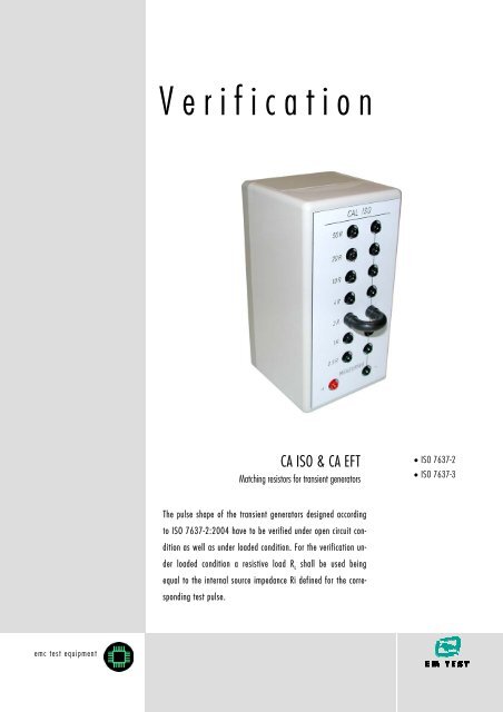
<strong>Verification</strong><br />
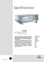
CA ISO & CA EFT<br />
Matching resistors for transient generators<br />
The pulse shape of the transient generators designed according<br />
to ISO 7637-2:2004 have to be verified under open circuit con-<br />
dition as well as under loaded condition. For the verification un-<br />
der loaded condition a resistive load R L shall be used being<br />
equal to the internal source impedance Ri defined for the corre-<br />
sponding test pulse.<br />
• ISO 7637-2<br />
• ISO 7637-3
CA ISO & CA EFT<br />
Transient generators which are designed on the basis of the ISO 7637-2; 2004 shall be verified under<br />
two different load conditions:<br />
a) under no load condition<br />
b) under matched load condition (Ri = RL)<br />
For this application 2 different sets of calibration resistors are available:<br />
- CA EFT is a set of coaxial matching resistors (50Ω & 1000Ω) including a 1:100 voltage divider.<br />
This is used to measure the fast pulses 3a/3b.<br />
- CA ISO is a set of matching resistors (0.5 –1.0 – 2.0 – 4.0 – 10 – 20 - 50Ω) which are used to<br />
measure the µs pulses and ms-pulses such as pulse 1, pulse 2 and pulse 5 and all derivatives.<br />
Care shall be taken for the selection of the resistors. They shall have sufficient power dissipation for pulse<br />
energy rating. Additionally, they shall be non-inductive.<br />
The UA and UB for this verification procedure shall be 0V (no battery supply voltage connected).<br />
The load impedance shall be selected to be equal to the source resistance defined for each test pulse.<br />
The tolerance of the matching resistor shall be ± 1%.<br />
CA EFT (see separate data sheet) CA ISO<br />
For verification of test pulses 3a/3b coaxial measuring<br />
devices shall be used. The spectrum of the pulses<br />
covers the frequency range up to 200 MHz. Within this<br />
range it is difficult to use high impedance voltage<br />
probes. The attached ground cable of the probe could<br />
cause significant ringing and give false measuring results.<br />
For the verification of micro pulses and load dump<br />
pulses resistive test loads are used with an accuracy of<br />
at least 1%. The CA ISO calibration adapter includes all<br />
resistors as required as per ISO 7637-2:2004, Annex D.<br />
The pulses can be measured by means of an oscilloscpe.<br />
<strong>EM</strong> TEST AG Tel: +41 (0)61 717 91 91<br />
Sternenhofstr. 15 Fax: +41 (0)61 717 91 99 CAISOverificationV101.doc<br />
CH-4153 Reinach email: sales@emtest.ch 20.03.07<br />
Switzerland URL http://www.emtest.com Page 2/4
The following load resistors are part of CA ISO:<br />
0.5Ω ±1% For measurement of load dump pulse 5 according to manufacturer specification<br />
1.0Ω ±1% For measurement of load dump pulse 5 according to manufacturer specification<br />
2.0Ω ±1% For measurement of pulse 2 and load dump pulse 5 according to ISO 7637-2<br />
and different manufacturer specifications<br />
4.0Ω ±1% For measurement of pulse 1, pulse 2 & load dump pulse 5 according to<br />
different manufacturer specification<br />
10Ω ±1% For measurement of pulse 1 & 2 according to ISO 7637-2 and different<br />
manufacturer specifications<br />
20Ω ±1% For measurement of pulse 1 & 2 according to ISO 7637-2 and different<br />
manufacturer specifications<br />
50Ω ±1% For measurement of pulse 1 according to ISO 7637-2 and different<br />
manufacturer specifications<br />
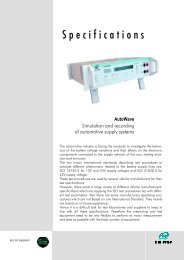
The CA ISO box is directly plugged into the +/- output of the transient generator.<br />
The adequate load resistor is selected by a short circuit connector. The wave<br />
shape across the load resistor is measured by a 1:100 voltage probe having a sufficient<br />
bandwidth and voltage capability, at least 20MHz and 1000V at the measuring<br />
terminals “+” (red) and “-“ (black).<br />
<strong>EM</strong> TEST AG Tel: +41 (0)61 717 91 91<br />
Sternenhofstr. 15 Fax: +41 (0)61 717 91 99 CAISOverificationV101.doc<br />
CH-4153 Reinach email: sales@emtest.ch 20.03.07<br />
Switzerland URL http://www.emtest.com Page 3/4
ISO 7637-2, Annex D <strong>Test</strong> pulse generator verification<br />
<strong>Test</strong> pulse 1 (12V system)<br />
Vs tr Td<br />
No load -100V ± 10V 1.0µs +0/-0.5µs 2000µs ± 400µs<br />
10Ω load - 50V ± 10V ---- 1500µs ± 300µs<br />
<strong>Test</strong> pulse 1 (24V system)<br />
Vs tr Td<br />
No load -600V ± 60V 3µs +0/-1.5µs 1000µs ± 200µs<br />
50Ω load -300V ± 30V ---- 1000µs ± 200µs<br />
<strong>Test</strong> pulse 2a (12V and 24V system)<br />
Vs tr Td<br />
No load +50V ± 5V 1.0µs +0/-0.5µs 50µs ± 10µs<br />
2Ω load +25V ± 5V ---- 12µs ± 2.4µs<br />
<strong>Test</strong> pulse 3a/3b (12V and 24V system)<br />
3a Vs tr Td<br />
No load -200V ± 20V 5ns ±1.5ns 150ns ± 45ns<br />
50Ω load -100V ± 20V 5ns ±1.5ns 150ns ± 45ns<br />
3b Vs tr td<br />
No load +200V ± 20V 5ns ±1.5ns 150ns ± 45ns<br />
50Ω load +100V ± 10V 5ns ±1.5ns 150ns ± 45ns<br />
<strong>Test</strong> pulse 5a (12V system)<br />
Vs tr Td<br />
No load +100V ± 10V 10ms +0/-5ms 400ms ± 80ms<br />
2Ω load +50V ± 10V ---- 200ms ± 40ms<br />
<strong>Test</strong> pulse 5a (24V system)<br />
Vs tr Td<br />
No load +200V ± 20V 10ms +0/-5ms 350ms ± 70 ms<br />
2Ω load +100V ± 20V ---- 175ms ± 35 ms<br />
<strong>EM</strong> TEST AG Tel: +41 (0)61 717 91 91<br />
Sternenhofstr. 15 Fax: +41 (0)61 717 91 99 CAISOverificationV101.doc<br />
CH-4153 Reinach email: sales@emtest.ch 20.03.07<br />
Switzerland URL http://www.emtest.com Page 4/4