Specifications - EM Test
Specifications - EM Test
Specifications - EM Test

Create successful ePaper yourself
Turn your PDF publications into a flip-book with our unique Google optimized e-Paper software.
emc test equipment<br />
<strong>Specifications</strong><br />
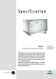
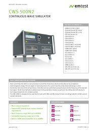
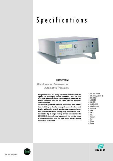
UCS 200M<br />
Ultra-Compact Simulator for<br />
Automotive Transients<br />
Designed to meet the many test needs of today and the<br />
rigours of converging world standards, the <strong>EM</strong> <strong>Test</strong><br />
UCS 200M generator offer a full range of conducted immunity<br />
transient tests to ISO, JASO, SAE and manufacturer<br />
standards.<br />
The distinct operation features, convenient DUT connection<br />
facilities, a clearly arranged menu structure and<br />
display philosophy as well as the preprogrammed standard<br />
test routines make testing easy, reliable and safe.<br />
Extendable by a large variety of test accessories the<br />
UCS 200M is the universal equipment for a wide range<br />
of recommendations even for high power battery supply<br />
application up to 200A.<br />
• ISO 7637-2-2004<br />
• SAE J1113 parts 11, 12<br />
• SAE J1455<br />
• JASO D001<br />
• GM 3097<br />
• Ford ES-XW7T<br />
• Chrysler PF9326<br />
• DC 10614<br />
• BMW<br />
• VW<br />
• PSA<br />
• Renault<br />
• Fiat<br />
• Nissan<br />
• Honda
S<br />
Burst module, Pulse 3a/3b<br />
Electrical Fast Transient Simulator based on ISO 7637-2:2004<br />
<strong>Test</strong> Level Output<br />
acc. to ISO 7637-2:2004<br />
<strong>Test</strong> voltage 25V – 1’000V ± 10%<br />
Rise time tr 5ns ± 1.5ns<br />
Pulse duration td 100ns (+100/-0)ns<br />
Verification As per Annex D of ISO 7637-2:2004 into a<br />
50Ω and a 1,000Ω load<br />
Source impedance Zq = 50Ω<br />
Polarity Pulse 3b positive and pulse 3a negative<br />
Trigger Circuit<br />
Trigger of bursts Automatic, manual, external<br />
Burst duration T4 = 0.1ms - 999.9ms<br />
Burst repetition rate T5 = 10ms - 9,999ms<br />
Spike frequency f = 0.1kHz - 200kHz<br />
<strong>Test</strong> duration T = 0:01min - 999:59min or endless<br />
Outputs<br />
Direct Via 50Ω-coaxial connector<br />
Coupling mode To the + battery line<br />
CRO trigger 5V trigger signal for oscilloscope<br />
<strong>Test</strong> Routines<br />
Quick Start On-line adjustable parameters, easy to use<br />
Standard <strong>Test</strong> Routines acc. to ISO 7637-2:2004, level 1 - 4<br />
User <strong>Test</strong> Routines User <strong>Test</strong> Routines<br />
Random burst release<br />
Change voltage after T by ∆T<br />
Change frequency after T by ∆f<br />
CRO trigger 5V trigger signal for oscilloscope<br />
Options<br />
ACC Capacitive coupling clamp acc. to ISO 7637 part 3<br />
KW50 100:1 divider, 50Ω<br />
KW1000 400:1 divider, 1000Ω<br />
CA EFT kit EFT/Burst verification kit<br />
A6dB 6dB attenuator, 50Ω<br />
ITP Immunity test probes (electrical field generation)<br />
ITP/H Immunity test probes (magnetic field generation<br />
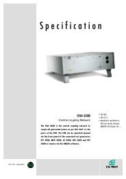
Coupling Matrix type CNA<br />
Technical data for standard CNA 50<br />
DUT supply voltage Max. 60V<br />
DUT supply current 50 A<br />
Inrush current capability 100A for 500ms<br />
Dimension UCS & CN 19“ / 3HU<br />
Technical data for optional CNA 100<br />
DUT supply voltage Max. 60V<br />
DUT supply current 100 A<br />
Inrush current capability 150A for 500ms<br />
Dimension UCS & CN 19“ / 6HU<br />
Technical data for optional CNA 150<br />
DUT supply voltage Max. 60V<br />
DUT supply current 150 A<br />
Inrush current capability 150 A<br />
Dimension UCS & CN 19“ / 9HU<br />
Technical data for optional CNA 200<br />
DUT supply voltage Max. 60V<br />
DUT supply current 200 A<br />
Inrush current capability 200 A<br />
Dimension UCS & CN 19“ / 9HU<br />
Input<br />
DUT supply +/- Simulator type VDS 200B & PFS 200B<br />
Pulse 5, 7 Standard for one type LD 200x<br />
Output<br />
+/- DUT supply Central DUT output<br />
Coaxial output port To connect the capacitive coupling clamp as<br />
per ISO 7637 part 3<br />
Interface<br />
CN interface To control the internal CN by external pulse<br />
generators such as LD 200B<br />
Option<br />
CNA Ext Extention to connect 3 additional generators<br />
<strong>EM</strong> TEST AG Tel: +41 (0)61 717 91 91<br />
Sternenhofstr. 15 Fax: +41 (0)61 717 91 99 ucs200m_eV115.doc<br />
CH-4153 Reinach email: sales@emtest.ch 09.08.07<br />
Switzerland URL http://www.emtest.com Page 2/4
Micropulse module,<br />
Pulse 1, 2 based on ISO 7637-2:2004<br />
<strong>Test</strong> Level Output<br />
Open circuit voltage U = 20V – 600V ± 10% ( Peak voltage<br />
and polarity acc. to the selected standard)<br />
Repetition rate 0.2s – 99.0s<br />
ISO Pulse 1 (12V)<br />
Rise time tr (10 - 90%) 1µs + 0% // - 50%<br />
Pulse duration td (10 - 10%) 2ms ± 10%<br />
Internal resistor 10Ω ± 10%<br />
ISO Pulse 1 (24V)<br />
Rise time tr (10 - 90%) 3µs + 0% // - 50%<br />
Pulse duration td (10 - 10%) 1ms ± 10%<br />
Internal resistor 50Ω ± 10%<br />
ISO Pulse 2 (12V/24V)<br />
Rise time tr (10 - 90%) 1µs + 0% // - 50%<br />
Pulse duration td (10 - 10%) 50µs ± 10%<br />
Internal resistor 2Ω ± 10%<br />
As per ISO 7637-2 the following standards can be covered<br />
SAE J1113 GM 3097<br />
BMW VW<br />
Chrysler PF 9326 PSA<br />
DC10614 Renault<br />
FIAT Mitsubishi<br />
Ford ES-XW7T Honda<br />
Option Pulse Programming Mode<br />
Rise time 1µs to 10µs with steps of 1µs<br />
Pulse duration 50µs to 10,000us<br />
Internal resitor 2Ω-100Ω in steps of 5Ω, 200, 400 & 450Ω<br />
Trigger<br />
Automatic Automatic release of the pulses<br />
Manual Manual release of a single pulse<br />
External External release of a single pulse<br />
Battery supply switch Selectable Off time, to = 0 – 10,000ms<br />
Output<br />
+/- output Central DUT output<br />
Coupling To the battery +line<br />
Decoupling Via diode and battery supply switch<br />
<strong>Test</strong> Routines<br />
Quick Start Immediate start; easy to use and fast<br />
User <strong>Test</strong> Routines 1. Custom made test routines<br />
2. Change voltage after n pulses by ∆V<br />
Pulse selctor<br />
Service Service, setup, self test<br />
Interface<br />
Serial interface RS 232, baud rate 1200 - 19200<br />
Parallel interface IEEE 488, address 1 - 30<br />
CN interface To control the internal CN and battery<br />
switch<br />
Micropulse module,<br />
Pulses based on Jaso and Nissan<br />
JASO D 001<br />
Pulse A2 as per JASO D 001<br />
<strong>Test</strong> voltage +110V<br />
Capacitor C = 4.7µF<br />
Pulse duration at τ τ(36,8%) = 2.5µs ± 30%<br />
R1 0.6Ω ± 10%<br />
R2 0.4Ω ± 10%<br />
Polarity Positive<br />
Pulse B2 as per JASO D 001<br />
<strong>Test</strong> voltage -260V<br />
Capacitor C = 33µF<br />
Pulse duration at τ τ(36,8%) = 2.0ms ± 20%<br />
R1 60Ω ± 10%<br />
R2 80Ω ± 10%<br />
Polarity Negative<br />
Pulse D2 as per JASO D 001<br />
<strong>Test</strong> voltage +170V<br />
Capacitor C = 2.2µF<br />
Pulse duration at τ τ(36,8%) = 2.5µs ± 30%<br />
R1 1.2Ω ± 10%<br />
R2 0.9Ω ± 10%<br />
Polarity Positive<br />
Nissan NDS<br />
Pulse B2 as per Nissan<br />
Open circuit voltage – 300V ± 10%<br />
Capacitor C = 33µF<br />
R1 100Ω ± 10%<br />
R2 75Ω ± 10%<br />
Polarity Negative<br />
Pulse C8 as per Nissan<br />
Open circuit voltage ±300V ± 10%<br />
Capacitor C = 1µF<br />
R1 500Ω ± 10%<br />
R2 450Ω ± 10%<br />
Polarity Positive and negative<br />
Pulse C50 as per Nissan<br />
Open circuit voltage ±300V ± 10%<br />
Capacitor C = 33µF<br />
R1 30Ω ± 10%<br />
R2 200Ω ± 10%<br />
Polarity Positive and negative<br />
Pulse C300 as per Nissan<br />
Open circuit voltage - 300V ± 10%<br />
Capacitor C = 33µF<br />
R1 100Ω ± 10%<br />
R2 75Ω ± 10%<br />
Polarity Negative<br />
<strong>EM</strong> TEST AG Tel: +41 (0)61 717 91 91<br />
Sternenhofstr. 15 Fax: +41 (0)61 717 91 99 ucs200m_eV115.doc<br />
CH-4153 Reinach email: sales@emtest.ch 09.08.07<br />
Switzerland URL http://www.emtest.com Page 3/4
Micropulse module,<br />
Pulses based on SAE J1455<br />
SAE J1455<br />
Mutual Pulse as per SAE J1455<br />
Rise time tr (10% - 90%) 1µs +20%<br />
Pulse duration td at τ 15µs ± 20%<br />
Internal resistor 50Ω ± 10%<br />
Inductive Pulse as per SAE J 1455<br />
Rise time tr (10 - 90%) 1µs ± 20%<br />
Pulse duration td at τ 1,000µs ± 20%<br />
Internal resistor 20Ω ± 10%<br />
Options<br />
CA ISO Micropulse/Load Dump pulse verification kit<br />
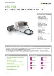
The SmartRack<br />
Sophisticated Housing for Sophisticated Instruments<br />
General data<br />
General data<br />
Dimensions, weight<br />
For models 50A 19“ / 3HU, approx. 20kg<br />
For models 100A 19“ / 6HU, approx. 30kg<br />
For models 150A and 200A 19“ / 9HU, approx. 35kg<br />
Supply voltage 115/230V +10/-15%<br />
Fuses 2 x T 2AT (230V) or 2 x T 4AT (115V)<br />
Options<br />
Rack For system integration; includes GPIB<br />
bus, pulse bus, ground reference plane,<br />
security switch and power contact.<br />
ISMISO Software to control the test, including<br />
standard library, test report facility and<br />
data conversion generator.<br />
UCS 200M 200A model<br />
The best place to put your generators is in the SmartRack. A wired, "intelligent"<br />
rack, the SmartRack not only holds, but also interconnects and<br />
controls equipment. Slide your generators into the SmartRack and you<br />
can run entire test routines from your PC with no plugging or unplugging,<br />
no stops or starts.<br />
Select from a comprehensive directory of the most recent preprogrammed<br />
international and manufacturer standards – including custom<br />
pulse waveforms – and the SmartRack does the rest. You can modify test<br />
parameters and even create your own tests.<br />
Just how easy is testing with the SmartRack? Consider this:<br />
• The Device Under <strong>Test</strong> (DUT) voltage has one easy connection at the<br />
UCS 200M coupling unit<br />
• No need to keep plugging and unplugging DUTs<br />
• The test rack has a ground reference plane that matches with the test<br />
table specified in ISO 7637-2:2004<br />
• ISM ISO (SmartRack) software controls the entire test process.<br />
It generates test reports as well<br />
• <strong>Test</strong>s can be initiated from front panels as well as from a PC<br />
Technical data subject to change without notice.<br />
<strong>EM</strong> TEST AG Tel: +41 (0)61 717 91 91<br />
Sternenhofstr. 15 Fax: +41 (0)61 717 91 99 ucs200m_eV115.doc<br />
CH-4153 Reinach email: sales@emtest.ch 09.08.07<br />
Switzerland URL http://www.emtest.com Page 4/4