Stability of the Master Oscillator for FLASH at DESY
Stability of the Master Oscillator for FLASH at DESY
Stability of the Master Oscillator for FLASH at DESY

You also want an ePaper? Increase the reach of your titles
YUMPU automatically turns print PDFs into web optimized ePapers that Google loves.
48 4 MASTER OSCILLATOR<br />
where PFD is <strong>the</strong> phasedetector frequency th<strong>at</strong> reads:<br />
PFD = fREF( ( 1 + D ) / R ) (28)<br />
where fREF is <strong>the</strong> reference frequency and D is a input frequency doubler Bit. The output<br />
frequency is adjustable due to equ<strong>at</strong>ion 27 by <strong>the</strong> variables<br />
1. R = 0...15<br />
2. INT = 0. . .511<br />
3. FRAC = 0. ..4095<br />
4. MOD = 0. ..4095<br />
and a doubler Bit D to double <strong>the</strong> input frequency 34 . Doubler Bit D is set <strong>of</strong>f and R divider is<br />
set to 4. An example <strong>for</strong> programming <strong>the</strong> registers is put in <strong>the</strong> appendix.<br />
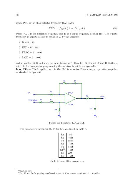
Loop Filter: The Loopfilter used in <strong>the</strong> PLL is an active Filter using an oper<strong>at</strong>ion amplifier<br />
as sketched in figure 59.<br />
CP<br />
Offsetvoltage<br />
R4<br />
R1<br />
R5<br />
R6<br />
R2 C1<br />
-<br />
+<br />
OPAMP<br />
LT1028<br />
R3<br />
C2<br />
0 0<br />
Figure 59: Loopfilter LOLA PLL<br />
The parameters chosen <strong>for</strong> <strong>the</strong> Filter here are listed in table 6.<br />
R1 0Ω<br />
R2 5kΩ<br />
C1 10nF<br />
R3 1kΩ<br />
C2 6.8nF<br />
R4 35 1kΩ<br />
R5 220Ω<br />
R6 1kΩ<br />
Table 6: Loop filter parameters<br />
34 disabled here<br />
34 R4, R5 and R6 <strong>for</strong> putting an <strong>of</strong>fsetvoltage <strong>of</strong> 1.8 V <strong>at</strong> positve pin <strong>of</strong> oper<strong>at</strong>ion amplifier<br />
Vtune