System # 2010
System # 2010
System # 2010

Create successful ePaper yourself
Turn your PDF publications into a flip-book with our unique Google optimized e-Paper software.
PROGRAMMING INSTRUCTION<br />
ELECTRONIC CHIP BOX LOCK<br />
The lock automatically recognizes the programming card and the data carrier included in the scope of delivery.<br />
However, programming can be changed at any time, as described in the following.<br />
Programming of the card<br />
Press the programming key (1) of the lock for three seconds until you hear a long acoustic signal followed by a ticking<br />
lasting for approx. 7 seconds. During the ticking signal hold the programming card (8) to the identifi cation zone (3) until<br />
you hear an acoustic signal of recognition. Now the card is programmed.<br />
Programming of the data carrier<br />
Hold the programming card (8) once to the identifi cation zone (3). A ticking lasting for 7 seconds is to be heard. During<br />
the ticking hold the data carrier (7) to the identifi cation zone (3) for read-in until you hear an acoustic signal of recognition.<br />
Now the data carrier is programmed.<br />
Control the data carrier as to its functioning<br />
Hold the data carrier (7) to the identifi cation zone (3) until you hear an acoustic recognition signal and until the spring<br />
advances. Hold the data carrier (7) once again tho the identifi cation zone (3) until you hear an acoustic recognition signal<br />
and the opening interval is started.<br />
Delete individual programmed data carriers<br />
Hold the programming card (8) once to the identifi cation zone (3) until you hear a ticking lasting for approx. 7 seconds.<br />
Hold the data carrier (7) for deletion to the identifi cation area during the ticking until hear a recognition signal. Now the<br />
data carrier is deleted.<br />
Delete all programmed data carriers<br />
Hold the programming card (8) to the identifi cation zone (3) until you hear four short acoustic signals followed by a long<br />
recognition signal. Now all the programmed data carrier are deleted und the spring has returned into opening position.<br />
Activate or deactivate the acoustic signal<br />
Push the programming key (1) for one second.<br />
All settings, for which the programming key (1) is not needed, can be made with the lock already mounted. The<br />
electronics of the lock is able to read the data carrier and the programming card even through materials of up<br />
to 20 mm thickness.<br />
Warning: The correct functioning can only be guaranteed if the lock is mounted on non-conducting materials (wood,<br />
synthetic material) with a max. thickness of 2 0 mm. In case of a higher thickness, with metal doors or doors with a metal<br />
application, anantenna has to be installed.<br />
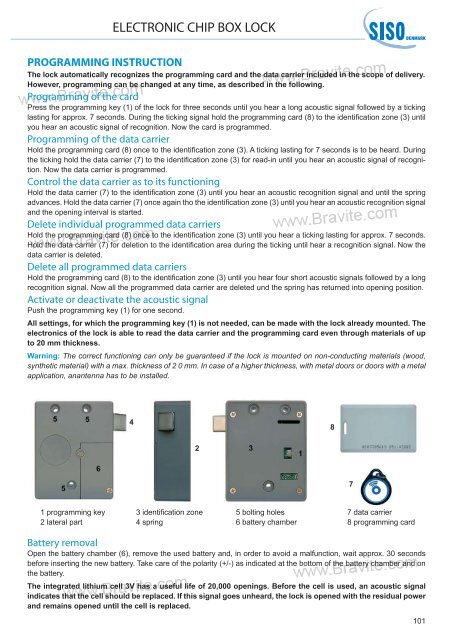
1 programming key<br />
2 lateral part<br />
4<br />
2<br />
3 identifi cation zone<br />
4 spring<br />
5 bolting holes<br />
6 battery chamber<br />
8<br />
7<br />
7 data carrier<br />
8 programming card<br />
Battery removal<br />
Open the battery chamber (6), remove the used battery and, in order to avoid a malfunction, wait approx. 30 seconds<br />
before inserting the new battery. Take care of the polarity (+/-) as indicated at the bottom of the battery chamber and on<br />
the battery.<br />
The integrated lithium cell 3V has a useful life of 20,000 openings. Before the cell is used, an acoustic signal<br />
indicates that the cell should be replaced. If this signal goes unheard, the lock is opened with the residual power<br />
and remains opened until the cell is replaced.<br />
101