Twin Disc HP 300, 600 service manual - Morbark
Twin Disc HP 300, 600 service manual - Morbark
Twin Disc HP 300, 600 service manual - Morbark

Create successful ePaper yourself
Turn your PDF publications into a flip-book with our unique Google optimized e-Paper software.
Operation<br />
38<br />
GP Control Valve Electronic Control Interface (Profile Module)<br />
<strong>Twin</strong> <strong>Disc</strong>, Incorporated<br />
The electronic portion of the GP Control Valve must be remotely mounted from<br />
the hydraulic portion of the GP Control Valve, because of the ambient<br />
temperature in most applications.<br />
If the ambient temperature of this mounting location exceeds 82 o C.<br />
(180 o F.), the Electronic Control Interface must be relocated to a cooler<br />
area. See Remote Mounted Electronic Control Cable in the Installation<br />
Section of this <strong>manual</strong><br />
This module contains the electronic circuitry to control the proportional cartridges<br />
that are used to engage the clutch and brake, based on the commands from<br />
the operator, and the programmed logic. Clutch apply pressure rate of rise<br />
(profile) is factory set with the use of internal circuitry. Closed loop logic is used<br />
for all clutch engagements. There are no user adjustments on the <strong>HP</strong>TO Profile<br />
Module. All electrical wiring for the Hydraulic Power Take Off system controls<br />
are routed through this interface module. The machine’s battery power (12 vdc<br />
or 24 vdc) is supplied to the electronic interface only, and never directly to the<br />
hydraulic proportional valves. Two red led lights are used to identify the<br />
proportional cartridge valve that is energized, and a green led is used to identify<br />
when power is provided to the electronic module. Flashing lights are used in<br />
troubleshooting. Engine speed and clutch output speed sensors are required<br />
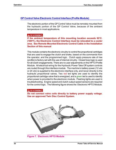
for the control logic. The following figure shows the Electronic <strong>HP</strong>TO Module.<br />
Do not connect valve coils directly to battery power supply voltage.<br />
Use an approved <strong>Twin</strong> <strong>Disc</strong> Control System.<br />
Figure 7. Electronic <strong>HP</strong>TO Module<br />
Power Take-off Service Manual