Service And Reference Manual - Support
Service And Reference Manual - Support
Service And Reference Manual - Support

You also want an ePaper? Increase the reach of your titles
YUMPU automatically turns print PDFs into web optimized ePapers that Google loves.
PROPRIETARY NOTICE AND LIABILITY DISCLAIMER<br />
The information disclosed in this document, including all designs and related materials, is<br />
the valuable property of NEC Computer Systems Division, Packard Bell NEC, Inc.<br />
(hereinafter “NECCSD, PB NEC”) and/or its licensors. NECCSD and/or its licensors, as<br />
appropriate, reserve all patent, copyright and other proprietary rights to this document, including<br />
all design, manufacturing, reproduction, use, and sales rights thereto, except to the<br />
extent said rights are expressly granted to others.<br />
The NECCSD product(s) discussed in this document are warranted in accordance with the<br />
terms of the Warranty Statement accompanying each product. However, actual<br />
performance of each such product is dependent upon factors such as system configuration,<br />
customer data, and operator control. Since implementation by customers of each product<br />
may vary, the suitability of specific product configurations and applications must be<br />
determined by the customer and is not warranted by NECCSD.<br />
To allow for design and specification improvements, the information in this document is<br />
subject to change at any time, without notice. Reproduction of this document or portions<br />
thereof without prior written approval of NECCSD is prohibited.<br />
FaxFlash is a service mark of NEC Computer Systems Division (NECCSD), Packard Bell NEC, Inc.<br />
NEC, MultiSync, and PowerMate are registered trademarks of NEC Corporation, used under license.<br />
All other product, brand, or trade names used in this publication are the trademarks or registered trademarks of their<br />
respective trademark owners.<br />
First Printing — October 1997<br />
Copyright 1997<br />
NEC Computer Systems Division<br />
Packard Bell NEC, Inc.<br />
1414 Massachusetts Avenue<br />
Boxborough, MA 01719-2298<br />
All Rights Reserved
Preface<br />
This manual contains technical information necessary for servicing and repairing the<br />
NEC PowerMate ® Enterprise minitower series of computers from NEC Computer Systems<br />
Division, Packard Bell NEC, Inc. The manual contains hardware and interface information<br />
for users who need an overview of system design. The manual also includes system setup<br />
information, procedures for installing options, and illustrated parts lists. The manual is<br />
written for NECCSD-trained customer engineers, system analysts, service center personnel,<br />
and dealers.<br />
The manual is organized as follows:<br />
Section 1 — Technical Information provides an overview of computer features and<br />
options, hardware design, interface ports, and internal devices. System specifications are<br />
listed including dimensions, weight, environment, safety compliance, power consumption,<br />
and memory.<br />
Section 2 — Setup and Operation includes unpacking, setup, and operation information.<br />
Procedures are also included for configuring the system with the BIOS Setup utility, setting<br />
passwords, using power management and security features, reinstalling the operating system<br />
or software, and using the BIOS Update utility.<br />
Section 3 — Option Installation provides installation procedures for adding optional<br />
expansion boards, additional storage devices, system memory, or a processor upgrade.<br />
Section 4 — Maintenance and Troubleshooting includes recommended maintenance<br />
information, along with possible computer problems and their solutions, and the procedures<br />
for battery replacement. NECCSD telephone numbers are provided for obtaining service,<br />
accessing the NECCSD Bulletin Board System, and accessing the NEC FaxFlash SM service.<br />
Section 5 — Repair includes computer disassembly and reassembly procedures. Also<br />
included are an exploded view diagram (Illustrated Parts Breakdown) and a parts lists for<br />
field-replaceable parts.<br />
Appendix A — Connector Pin Assignments provides a list of system, riser, and option<br />
board internal connector pin assignments and a list of external pin assignments for the<br />
keyboard, mouse, serial ports, parallel port, network ports, and video port.<br />
Appendix B —Jumper Settings provides jumper settings for the system board, and for<br />
options that may ship with the computer, including the CD-ROM reader and the fax/modem<br />
board.<br />
xv
Contents<br />
iii<br />
Page<br />
Preface......................................................................................................................... xiii<br />
Abbreviations............................................................................................................... xv<br />
Section 1 Technical Information<br />
System Overview......................................................................................................... 1-1<br />
System Board .............................................................................................................. 1-5<br />
Processor and Secondary Cache............................................................................ 1-7<br />
System BIOS ........................................................................................................ 1-8<br />
I/O Addressing...................................................................................................... 1-10<br />
System Memory.................................................................................................... 1-12<br />
Hardware Monitor ................................................................................................ 1-13<br />
Interrupt Controller............................................................................................... 1-13<br />
Plug and Play ........................................................................................................ 1-15<br />
NLX Chassis......................................................................................................... 1-15<br />
ISA Bus................................................................................................................ 1-15<br />
PCI Local Bus ...................................................................................................... 1-15<br />
PCI/IDE Ports ...................................................................................................... 1-16<br />
Parallel Interface ................................................................................................... 1-16<br />
Serial Interface...................................................................................................... 1-17<br />
USB Interface....................................................................................................... 1-18<br />
Infrared Interface .................................................................................................. 1-18<br />
Video Interface ..................................................................................................... 1-19<br />
Integrated Audio................................................................................................... 1-20<br />
Diskette Drive.............................................................................................................. 1-21<br />
Hard Disk Drive........................................................................................................... 1-21<br />
CD-ROM Reader......................................................................................................... 1-21<br />
Power Supply .............................................................................................................. 1-22<br />
Keyboard..................................................................................................................... 1-22<br />
Mouse ......................................................................................................................... 1-22<br />
Speakers ...................................................................................................................... 1-22<br />
Fax/Modem Board....................................................................................................... 1-22
iv Contents<br />
Video Board ................................................................................................................ 1-23<br />
Video <strong>Support</strong> ...................................................................................................... 1-23<br />
Video Playback..................................................................................................... 1-24<br />
Sound Board................................................................................................................ 1-24<br />
Network Boards .......................................................................................................... 1-25<br />
SCSI Adapter Board.................................................................................................... 1-25<br />
Specifications............................................................................................................... 1-27<br />
Section 2 Setup and Operation<br />
Unpacking and Repacking............................................................................................ 2-1<br />
Setup ........................................................................................................................... 2-2<br />
System Controls........................................................................................................... 2-8<br />
Power Button ....................................................................................................... 2-8<br />
Suspend Button .................................................................................................... 2-9<br />
Reset Button......................................................................................................... 2-9<br />
CD-ROM Reader......................................................................................................... 2-9<br />
BIOS Setup Utility....................................................................................................... 2-12<br />
Using the BIOS Setup Utility ................................................................................ 2-12<br />
How to Start Setup............................................................................................... 2-13<br />
How to Use Setup................................................................................................. 2-14<br />
Main Menu ........................................................................................................... 2-15<br />
Processor Type .............................................................................................. 2-15<br />
Processor Speed............................................................................................. 2-15<br />
Cache RAM................................................................................................... 2-16<br />
Total Memory................................................................................................ 2-16<br />
BIOS Version ................................................................................................ 2-16<br />
Language ....................................................................................................... 2-16<br />
System Date/Time.......................................................................................... 2-16<br />
Floppy Options .............................................................................................. 2-16<br />
IDE Devices................................................................................................... 2-17<br />
Advanced Menu.................................................................................................... 2-18<br />
Plug and Play OS ........................................................................................... 2-19<br />
Reset Configuration Data ............................................................................... 2-19<br />
Memory Cache............................................................................................... 2-19<br />
Memory Bank 0/Memory Bank 1 ................................................................... 2-19<br />
Resource Configuration.................................................................................. 2-19<br />
Peripheral Configuration ................................................................................ 2-19
Contents v<br />
Keyboard Configuration................................................................................. 2-21<br />
Video Configuration....................................................................................... 2-22<br />
DMI Event Logging....................................................................................... 2-22<br />
Security Menu....................................................................................................... 2-22<br />
User Password Is ........................................................................................... 2-23<br />
Supervisor Password Is.................................................................................. 2-23<br />
Set User Password and Set Supervisor Password ........................................... 2-23<br />
Unattended Start............................................................................................ 2-23<br />
Power Management Menu .................................................................................... 2-24<br />
Power Management ....................................................................................... 2-24<br />
Inactivity Timer.............................................................................................. 2-24<br />
Hard Drive..................................................................................................... 2-25<br />
VESA Video Power Down ............................................................................ 2-25<br />
Boot Menu ........................................................................................................... 2-25<br />
Scan User Flash Area ..................................................................................... 2-26<br />
Restore on AC/Power Loss............................................................................ 2-26<br />
On Modem Ring ............................................................................................ 2-26<br />
On LAN......................................................................................................... 2-26<br />
On PME......................................................................................................... 2-26<br />
Boot Order .................................................................................................... 2-26<br />
Hard Drive..................................................................................................... 2-27<br />
Removable Devices........................................................................................ 2-27<br />
Boot Time Diagnostic Screen......................................................................... 2-27<br />
Floppy Check................................................................................................. 2-27<br />
Virus Check Reminder ................................................................................... 2-27<br />
System Backup Reminder............................................................................... 2-28<br />
Fixed Disk Boot Sector.................................................................................. 2-28<br />
Exit Menu............................................................................................................. 2-28<br />
Exit Saving Changes ...................................................................................... 2-28<br />
Exit Discarding Changes ................................................................................ 2-28<br />
Load Setup Defaults....................................................................................... 2-29<br />
Load Custom Defaults ................................................................................... 2-29<br />
Save Custom Defaults.................................................................................... 2-29<br />
Discard Changes ............................................................................................ 2-29<br />
Maintenance Menu................................................................................................ 2-29<br />
SCSISelect Utility........................................................................................................ 2-29
vi Contents<br />
BIOS Update Utility .................................................................................................... 2-30<br />
Downloading the BIOS Update Utility .................................................................. 2-30<br />
Using the BIOS Update Utility.............................................................................. 2-31<br />
Setting Auto Insert Notification ................................................................................... 2-32<br />
LANDesk Client Manager............................................................................................ 2-32<br />
PC Health Indicator .............................................................................................. 2-33<br />
Managing Workstations ................................................................................. 2-33<br />
PC Health Meter ............................................................................................ 2-34<br />
PC Health Description.................................................................................... 2-34<br />
Inventory .............................................................................................................. 2-34<br />
DMI...................................................................................................................... 2-35<br />
Monitoring Capabilities .................................................................................. 2-35<br />
Cheyenne Backup ................................................................................................. 2-36<br />
NEC Security........................................................................................................ 2-36<br />
NEC Select Install CD ................................................................................................. 2-36<br />
Operating System Restore Program....................................................................... 2-37<br />
Selective Application Restore Program ................................................................. 2-45<br />
Section 3 Option Installation<br />
General Rules for Installing Options............................................................................. 3-2<br />
Precautions .................................................................................................................. 3-2<br />
System Unit Cover and Stand....................................................................................... 3-3<br />
Removing the System Unit Cover and Stand ......................................................... 3-4<br />
Removing the System Unit Cover................................................................... 3-4<br />
Removing the System Unit Stand ................................................................... 3-6<br />
Replacing the System Unit Stand and Cover.......................................................... 3-7<br />
Replacing the System Unit Stand.................................................................... 3-7<br />
Replacing the System Unit Cover ................................................................... 3-7<br />
Chassis Floor ............................................................................................................... 3-9<br />
Removing the Chassis Floor.................................................................................. 3-9<br />
Replacing the Chassis Floor .................................................................................. 3-10<br />
Expansion Boards ........................................................................................................ 3-11<br />
Expansion Slot Locations...................................................................................... 3-11<br />
Expansion Board Installation................................................................................. 3-12<br />
Wake on LAN Cabling.......................................................................................... 3-13<br />
Expansion Board Removal .................................................................................... 3-14
Contents vii<br />
DIMM Memory Module Upgrade................................................................................ 3-15<br />
Checking System Memory..................................................................................... 3-15<br />
DIMM Module Removal.............................................................................................. 3-17<br />
DIMM Module Installation ................................................................................... 3-18<br />
Processor Upgrade....................................................................................................... 3-19<br />
Removing the Processor........................................................................................ 3-19<br />
Installing the Processor ......................................................................................... 3-21<br />
Data Storage Devices................................................................................................... 3-22<br />
Device Slots.......................................................................................................... 3-22<br />
Device Preparation................................................................................................ 3-23<br />
Device Cables ....................................................................................................... 3-25<br />
Diskette Drive Signal Cable............................................................................ 3-26<br />
IDE Signal Cables.......................................................................................... 3-27<br />
SCSI Signal Cable.......................................................................................... 3-28<br />
System Power Cables..................................................................................... 3-29<br />
Device Cabling...................................................................................................... 3-30<br />
Cabling an IDE Device................................................................................... 3-30<br />
Cabling a Diskette Drive ................................................................................ 3-31<br />
Cabling an Internal SCSI Device .................................................................... 3-32<br />
5 1/4-Inch Storage Device Installation................................................................... 3-32<br />
Removing the Front Panel .............................................................................. 3-32<br />
Installing a 5 1/4-Inch Device......................................................................... 3-35<br />
Replacing the Front Panel............................................................................... 3-37<br />
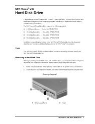
3 1/2-Inch Hard Disk Drive Installation................................................................. 3-38<br />
Removing a 3 1/2-Inch Hard Drive................................................................. 3-38<br />
Installing a 3 1/2-Inch Internal Hard Drive...................................................... 3-40<br />
External Options.......................................................................................................... 3-41<br />
Connecting a Parallel Printer ................................................................................. 3-42<br />
Connecting an RS-232C Device ............................................................................ 3-43<br />
Connecting a USB Device..................................................................................... 3-44<br />
Connecting an Optional External Wide SCSI Device ............................................. 3-44<br />
Section 4 Maintenance and Troubleshooting<br />
Online <strong>Service</strong>s ............................................................................................................ 4-2<br />
NECCSD FaxFlash <strong>Service</strong>................................................................................... 4-2<br />
NECCSD Bulletin Board System .......................................................................... 4-3
viii Contents<br />
E-Mail/Fax Technical <strong>Support</strong> <strong>Service</strong>s................................................................. 4-4<br />
Internet................................................................................................................. 4-5<br />
NECCSD Diskette Fulfillment Center .......................................................................... 4-5<br />
Maintenance ................................................................................................................ 4-6<br />
System Cleaning.................................................................................................... 4-6<br />
Keyboard Cleaning................................................................................................ 4-7<br />
Mouse Cleaning .................................................................................................... 4-8<br />
Troubleshooting........................................................................................................... 4-9<br />
Diagnosing and Solving Problems ......................................................................... 4-9<br />
Replacing the CMOS Battery................................................................................ 4-14<br />
Section 5 Repair<br />
Disassembly and Reassembly........................................................................................ 5-1<br />
System Unit Cover Removal ................................................................................. 5-2<br />
Chassis Floor Removal.......................................................................................... 5-2<br />
Expansion Board Removal .................................................................................... 5-3<br />
Front Panel Removal............................................................................................. 5-4<br />
Blank Panel and Metal Slot Cover Removal .......................................................... 5-5<br />
Expansion Board Guide Removal.......................................................................... 5-6<br />
Switch Board/IR Panel Assembly Removal............................................................ 5-6<br />
DIMM Module Removal....................................................................................... 5-7<br />
Processor Removal ............................................................................................... 5-8<br />
5 1/4-Inch Device Removal................................................................................... 5-9<br />
3 1/2-Inch Hard Disk Drive Removal .................................................................... 5-11<br />
3 1/2-Inch Diskette Drive Removal ....................................................................... 5-12<br />
Power Supply Removal......................................................................................... 5-13<br />
System Board Removal......................................................................................... 5-14<br />
Grounding Bracket Removal .......................................................................... 5-16<br />
Plastic Rail Removal ...................................................................................... 5-17<br />
Riser Board Removal ............................................................................................ 5-18<br />
Illustrated Parts Breakdown......................................................................................... 5-19<br />
Appendix A Connector Pin Assignments<br />
System Board Connector Locations ............................................................................. A-1<br />
Riser Board Connector Locations ................................................................................ A-3<br />
Parallel Interface Connector......................................................................................... A-4
Contents ix<br />
Serial Interface Connectors .......................................................................................... A-5<br />
Keyboard and Mouse Connectors................................................................................. A-6<br />
VGA Interface Connector ............................................................................................ A-7<br />
Microphone In Connector ............................................................................................ A-8<br />
Line Out Connector ..................................................................................................... A-8<br />
Universal Serial Bus Connectors .................................................................................. A-8<br />
Memory Module Connectors........................................................................................ A-9<br />
Storage Device Connectors.......................................................................................... A-11<br />
Diskette Drive Connector...................................................................................... A-11<br />
IDE Connectors.................................................................................................... A-12<br />
Feature Connector ....................................................................................................... A-13<br />
ISA Connectors ........................................................................................................... A-14<br />
PCI Connectors ........................................................................................................... A-15<br />
CD Audio In Connector............................................................................................... A-16<br />
Modem In Connector................................................................................................... A-16<br />
Power Supply Connectors............................................................................................ A-17<br />
Remote Wakeup Connector ......................................................................................... A-17<br />
Network Connectors.................................................................................................... A-18<br />
RJ-45 Connectors .................................................................................................A-18<br />
BNC Port Connectors........................................................................................... A-18<br />
Appendix B Jumper Settings<br />
System Board Jumper Settings..................................................................................... B-1<br />
Processor Jumpers ................................................................................................ B-2<br />
Password Clear Jumper......................................................................................... B-3<br />
BIOS Recovery Jumpers ....................................................................................... B-4<br />
Hard Disk Drive Jumper Settings ................................................................................. B-4<br />
Quantum Fireball Stratus Hard Disk Drive Jumper Settings................................... B-4<br />
Seagate Medalist Hard Disk Drive Jumper Settings ............................................... B-5<br />
Quantum Viking SCSI Hard Disk Drive Jumper Settings....................................... B-6<br />
Seagate Barracuda SCSI Hard Disk Drive Jumper Settings ................................... B-7<br />
CD-ROM Jumper Settings ........................................................................................... B-8<br />
56-Kbps Fax/Modem Board Jumper Settings ............................................................... B-8<br />
Seagate Tape Backup Drive Jumper Settings................................................................ B-8<br />
Iomega Zip Drive Jumper Settings ............................................................................... B-9
x Contents<br />
Glossary<br />
Index<br />
Figures<br />
1-1 PowerMate Enterprise Minitower Components .............................................. 1-1<br />
1-2 PowerMate Enterprise Minitower Front View................................................ 1-3<br />
1-3 PowerMate Enterprise Minitower Rear View ................................................. 1-3<br />
2-1 Installing the System Stand............................................................................. 2-2<br />
2-2 Voltage Selector Switch................................................................................. 2-3<br />
2-3 Peripheral Connections................................................................................... 2-4<br />
2-4 Fax/Modem Connections................................................................................ 2-4<br />
2-5 Nine-Watt Speakers ....................................................................................... 2-5<br />
2-6 Right Speaker Connections ............................................................................ 2-6<br />
2-7 Audio Connectors on the System Board ......................................................... 2-6<br />
2-8 Audio Connectors on a Sound Board ............................................................. 2-7<br />
2-9 Network Connectors...................................................................................... 2-7<br />
2-10 Buttons and Lamps on the Front Panel ........................................................... 2-8<br />
2-11 Basic CD-ROM Reader Controls and Indicators............................................. 2-10<br />
2-12 Main Menu .................................................................................................... 2-13<br />
2-13 Welcome Screen ............................................................................................ 2-38<br />
2-14 Restore Mode Screen..................................................................................... 2-39<br />
2-15 Partition Information Screen .......................................................................... 2-39<br />
2-16 FAT16 Partition Screen.................................................................................. 2-40<br />
2-17 Restore Mode Screen..................................................................................... 2-41<br />
2-18 Partitioning the Hard Drive Screen................................................................. 2-41<br />
2-19 Format Mode Screen...................................................................................... 2-42<br />
2-20 Installing Application Screen.......................................................................... 2-43<br />
2-21 Partition Information Screen .......................................................................... 2-43<br />
2-22 FAT16 Partition Screen.................................................................................. 2-44<br />
2-23 Selective Application Restore Screen ............................................................. 2-45<br />
3-1 Internal Options ............................................................................................. 3-1<br />
3-2 Loosening Cover Screws................................................................................ 3-4<br />
3-3 Removing the Cover ...................................................................................... 3-5<br />
3-4 Removing the System Unit Stand ................................................................... 3-6<br />
3-5 Aligning the Cover......................................................................................... 3-8
Contents xi<br />
3-6 Loosening the Chassis Floor Thumb Screw .................................................... 3-9<br />
3-7 Removing the Chassis Floor ........................................................................... 3-10<br />
3-8 Locating Expansion Slots............................................................................... 3-11<br />
3-9 Removing a Slot Cover .................................................................................. 3-12<br />
3-10 Removing an Expansion Board....................................................................... 3-14<br />
3-11 System Board Upgrade Sockets ..................................................................... 3-16<br />
3-12 Removing a DIMM........................................................................................ 3-17<br />
3-13 Inserting the DIMM ....................................................................................... 3-18<br />
3-14 Releasing the Heatsink Clamp ........................................................................ 3-20<br />
3-15 Aligning the Processor with the Socket .......................................................... 3-21<br />
3-16 Data Storage Slots ......................................................................................... 3-22<br />
3-17 Riser Board Cable Connectors ....................................................................... 3-25<br />
3-18 Three-Connector Diskette Drive Signal Cable ................................................ 3-26<br />
3-19 IDE Signal Cable ........................................................................................... 3-27<br />
3-20 SCSI Signal Cable Connectors ....................................................................... 3-28<br />
3-21 Power Cable Connectors................................................................................ 3-29<br />
3-22 Connecting IDE Device Cables ...................................................................... 3-30<br />
3-23 Connecting 1.2-MB Diskette Drive Cables ..................................................... 3-31<br />
3-24 Removing the Front Panel .............................................................................. 3-33<br />
3-25 Locating the Blank Panel Tabs ....................................................................... 3-34<br />
3-26 Attaching the Device Rails ............................................................................. 3-35<br />
3-27 Inserting a Device .......................................................................................... 3-36<br />
3-28 Aligning the Front Panel................................................................................. 3-37<br />
3-29 Removing the Inner Hard Drive Screws ......................................................... 3-39<br />
3-30 Removing the Outer Hard Drive Screws......................................................... 3-40<br />
3-31 Connecting a Printer Cable............................................................................. 3-42<br />
3-32 Connecting the RS-232C Cable...................................................................... 3-43<br />
3-33 Connecting an External SCSI Device Cable.................................................... 3-44<br />
4-1 Removing the Keyboard Enclosure................................................................. 4-7<br />
4-2 Removing the Mouse Ball Cover.................................................................... 4-8<br />
4-3 Locating the Battery....................................................................................... 4-14<br />
4-4 Removing the Battery .................................................................................... 4-15<br />
5-1 Removing the Expansion Board ..................................................................... 5-3<br />
5-2 Removing the Front Panel .............................................................................. 5-4<br />
5-3 Removing the Blank Panel.............................................................................. 5-5
xii Contents<br />
5-4 Removing a DIMM Module ........................................................................... 5-7<br />
5-5 Releasing the Heatsink Clamp ........................................................................ 5-8<br />
5-6 Locating the Locking Tabs on the 5 1/4-Inch Device...................................... 5-9<br />
5-7 Removing a 5 1/4-Inch Device ....................................................................... 5-10<br />
5-8 Removing the Inner Hard Disk Drive Screws ................................................. 5-11<br />
5-9 Removing the Outer Hard Disk Drive Screws................................................. 5-12<br />
5-10 Removing the Power Supply Screws .............................................................. 5-13<br />
5-11 Unlatching the System Board ......................................................................... 5-14<br />
5-12 Removing the System Board .......................................................................... 5-15<br />
5-13 Removing the System Board Grounding Bracket............................................ 5-16<br />
5-14 Removing the System Board Plastic Rail ........................................................ 5-17<br />
5-15 Locating the Riser Board Screws ................................................................... 5-18<br />
5-16 PowerMate Enterprise Minitower Illustrated Parts Breakdown....................... 5-22<br />
A-1 System Board External Connector Locations.................................................. A-1<br />
A-2 System Board Internal Connector Locations................................................... A-2<br />
A-3 Riser Board Connector Locations................................................................... A-3<br />
A-4 Parallel Interface Connector ........................................................................... A-4<br />
A-5 Serial Interface Connectors ............................................................................ A-5<br />
A-6 PS/2-Style Keyboard and Mouse Interface Connectors................................... A-6<br />
A-7 VGA Interface Connector .............................................................................. A-7<br />
A-8 Power Supply Connector Pin Assignments ..................................................... A-17<br />
B-1 System Board Jumper Locations .................................................................... B-2<br />
B-2 Password Clear Jumper.................................................................................. B-3<br />
B-3 Quantum Hard Disk Drive Connector and Jumper Locations.......................... B-4<br />
Tables<br />
1-1 PowerMate Enterprise Minitower System Configuration ................................ 1-4<br />
1-2 System Board Feature Components................................................................ 1-7<br />
1-3 System Memory Map..................................................................................... 1-9<br />
1-4 I/O Address Map ........................................................................................... 1-10<br />
1-5 Memory Configurations ................................................................................. 1-12<br />
1-6 Interrupt Level Assignments........................................................................... 1-14<br />
1-7 DMA Settings................................................................................................ 1-14<br />
1-8 Parallel Port Addresses and Interrupts ............................................................ 1-16<br />
1-9 Serial Port 1 Addresses and Interrupts............................................................ 1-17
Contents xiii<br />
1-10 Serial Port 2 Addresses and Interrupts............................................................ 1-18<br />
1-11 <strong>Support</strong>ed Resolutions, Colors, and Refresh Rates ......................................... 1-20<br />
1-12 System Board Specifications .......................................................................... 1-27<br />
1-13 General Specifications.................................................................................... 1-28<br />
1-14 Riser Board Specifications ............................................................................. 1-28<br />
1-15 Keyboard Specifications................................................................................. 1-28<br />
1-16 Speaker Specifications ................................................................................... 1-29<br />
1-17 System Unit Specifications ............................................................................. 1-29<br />
1-18 Diskette Drive Specifications.......................................................................... 1-30<br />
1-19 1-GB Seagate Medalist EIDE Hard Disk Drive Specifications ........................ 1-31<br />
1-20 2.1-GB Quantum Fireball ST Hard Disk Drive Specifications......................... 1-32<br />
1-21 3.2-GB Quantum Fireball ST Hard Disk Drive Specifications......................... 1-33<br />
1-22 4.3-GB Quantum Fireball ST Hard Disk Drive Specifications......................... 1-34<br />
1-23 6.4-GB Quantum Fireball ST Hard Disk Drive Specifications......................... 1-35<br />
1-24 4.5-GB Quantum Viking Ultra Wide SCSI-3 Hard Disk Specifications........... 1-36<br />
1-25 4.5-GB Seagate Barracuda Ultra Wide SCSI Hard Disk Specifications........... 1-37<br />
1-26 24X CD-ROM Reader Specifications ............................................................. 1-38<br />
1-27 Fax/Modem Board Specifications................................................................... 1-39<br />
1-28 Number Nine Video Board Specifications ...................................................... 1-40<br />
1-29 Sound Board Specifications............................................................................ 1-41<br />
1-30 3COM 3C905-TX Network Board Specifications .......................................... 1-42<br />
1-31 3COM 3C509B-COMBO Network Board Specifications ............................... 1-42<br />
1-32 Intel EtherExpress Pro/100 Network Board Specifications ............................. 1-43<br />
1-33 NLX200 Watt Power Supply Specifications ................................................... 1-43<br />
1-34 Mouse Specifications ..................................................................................... 1-44<br />
2-1 Navigation Keys............................................................................................. 2-14<br />
3-1 DIMM Memory Module Options ................................................................... 3-15<br />
3-2 IDE Device Primary/Secondary Master/Slave Configurations ......................... 3-24<br />
4-1 NECCSD <strong>Service</strong> and <strong>Support</strong> Telephone Numbers ....................................... 4-1<br />
4-2 Problems and Solutions.................................................................................. 4-9<br />
5-1 PowerMate Enterprise Disassembly Sequence ................................................ 5-1<br />
5-2 Ordering Parts and Options ............................................................................ 5-19<br />
5-3 PowerMate Enterprise Minitower FRU List ................................................... 5-19<br />
5-4 PowerMate Enterprise Documentation and Packaging.................................... 5-21
xiv Contents<br />
A-1 System Board Connectors.............................................................................. A-2<br />
A-2 Riser Board Connectors ................................................................................. A-3<br />
A-3 Option Board Connectors .............................................................................. A-4<br />
A-4 Parallel Interface Pin Assignments.................................................................. A-5<br />
A-5 Serial Interface Pin Assignments..................................................................... A-6<br />
A-6 Keyboard and Mouse Pin Assignments........................................................... A-6<br />
A-7 VGA Interface Connector Pin Assignments.................................................... A-7<br />
A-8 Microphone In Connector Pin Assignments.................................................... A-8<br />
A-9 Line Out Connector Pin Assignments ............................................................. A-8<br />
A-10 Universal Serial Bus Connector Pin Assignments............................................ A-8<br />
A-11 DIMM Module Pin Assignments .................................................................... A-9<br />
A-12 Diskette Drive Pin Assignments...................................................................... A-11<br />
A-13 IDE Interface Pin Assignments....................................................................... A-12<br />
A-14 Feature Connector Pin Assignments ............................................................... A-13<br />
A-15 ISA Bus Pin Assignments............................................................................... A-14<br />
A-16 PCI Bus Pin Assignments............................................................................... A-15<br />
A-17 CD Audio-In Connector Pin Assignments....................................................... A-16<br />
A-18 Modem-In Connector Pin Assignments .......................................................... A-16<br />
A-19 Power Connector Pin Assignments................................................................. A-17<br />
A-20 Wake On LAN Connector Pin Assignments.................................................... A-17<br />
A-21 RJ-45 Connector Pin Assignments.................................................................. A-18<br />
A-22 BNC Port Pin Assignments ............................................................................ A-18<br />
B-1 Processor Speed and Processor Bus Speed Jumper Settings ........................... B-2
Section 1<br />
Technical Information<br />
SYSTEM OVERVIEW<br />
NEC PowerMate ® Enterprise minitower computers are built-to-order systems for<br />
commercial offices. All models come with in-demand features including two DIMM<br />
sockets, SDRAM system memory, an Intel ® Pentium ® processor, and a Plug and Play I/O<br />
controller. The computer features two USB ports, two serial ports, and an infrared port.<br />
Ultra DMA, remote wakeup (“Wake on LAN”), 3D graphics, and power management are<br />
supported. The system is designed in conformance with NLX standards so the system board<br />
is free of internal cabling and secured in the chassis with simple latches.<br />
Build choices include IDE hard disk drives ranging from 1.0 GB to 6.4 GB, and an ultra<br />
wide SCSI 4.55-GB hard disk drive. System memory is provided in 16-MB, 32-MB, and<br />
(as available) 64-MB and 128-MB DIMM sticks. Memory configurations range from<br />
16 MB to 256 MB. Additional choices include Pentium MMX technology, on-board<br />
sound, expansion boards for fax/modem, sound, video, networking, and peripheral devices<br />
such as CD-ROM readers.<br />
Figure 1-1 shows the components shipped with the PowerMate Enterprise minitower<br />
system (the speakers are optional).<br />
Figure 1-1 PowerMate Enterprise Minitower Components
1-2 Technical Information<br />
The basic hardware features for the PowerMate Enterprise minitower are listed below:<br />
� Intel CN430TX system board<br />
� Intel Pentium 166-MHz processor<br />
Intel Pentium 200-MHz processor<br />
Intel Pentium 166-MHz MMX processor<br />
Intel Pentium 200-MHz MMX processor<br />
Intel Pentium 233-MHz MMX processor<br />
� two 168-pin DIMM sockets; system memory from 16 MB using 16-MB, 32-MB,<br />
and (per availability) 64-MB or 128-MB sticks; upgradeable to 256 MB<br />
� S3 ® Trio 64 ViRGE/GX graphics chip integrated on system board<br />
� 2 MB of Video EDO RAM<br />
� 512-KB pipeline burst cache memory<br />
� 1.0-GB, 2.1-GB, 3.2-GB, 4.3-GB, or 6.4-GB hard disk drive, or 4.55-GB SCSI<br />
hard disk drive<br />
� 1.44-MB diskette drive<br />
� Yamaha OPL3-SA3 system integrated on the system board in some systems<br />
� Chicony 104 keyboard<br />
� Microsoft ® IntelliMouse ® .<br />
The following hardware features are build-to-order choices:<br />
� stereo speakers, 9-watt<br />
� 24X CD-ROM reader<br />
� 56.6-Kbps fax/modem board<br />
� Creative Labs CT4335 sound board (AWE32)<br />
� Number Nine ® Revolution 3D video board with 4 MB of video EDO<br />
� Intel EtherExpress Pro/100 network board with RJ-45 connector and remote<br />
wakeup connector<br />
3COM ® 3C905TX network board with RJ-45, BNC, and AUI connectors<br />
3COM 3C905B-Combo network board with RJ-45 connector<br />
� Iomega ® 100-MB Zip drive<br />
� Travan4 8-GB Tape Backup device.
Technical Information 1-3<br />
Figure 1-2 identifies the components, lamps, and controls on the front of the system.<br />
Figure 1-3 identifies the connectors on the back of the system.<br />
Figure 1-2 PowerMate Enterprise Minitower Front View<br />
Figure 1-3 PowerMate Enterprise Minitower Rear View
1-4 Technical Information<br />
PowerMate Enterprise computers are configured according to Table 1-1.<br />
Table 1-1 PowerMate Enterprise Minitower System Configuration<br />
Component Description<br />
System Unit<br />
System Board Intel CN430TX (with or without sound)<br />
CPU* Pentium 166 MHz<br />
Pentium 200 MHz<br />
Pentium 166 MHz MMX<br />
Pentium 200 MHz MMX<br />
Pentium 233 MHz MMX<br />
System RAM* 16 MB to 256 MB of SDRAM in 2 DIMM sockets<br />
Hard Disk Drive* Seagate Medalist 1010 EIDE non-Ultra DMA<br />
1.0 GB (ST31012A)<br />
Quantum Fireball Stratus IDE Ultra DMA/33:<br />
2.1 GB (ST21A011-02-B-H)<br />
3.2 GB (ST32A011-02-B-H)<br />
4.3 GB (ST43A011-02-C-H)<br />
6.4 GB (ST64A011-02-C-H)<br />
Quantum Viking or Seagate Barracuda Ultra Wide SCSI<br />
4.5 GB (VK45W012-04-G or ST34572W)<br />
Cache 512-KB Pipeline Burst SRAM<br />
Graphics S3 Trio 64 ViRGE/GX 3D Graphics on system board<br />
Video DRAM 2 MB of SGRAM soldered on system board<br />
Audio** Yamaha OPL3-SA3 (multimedia systems only)<br />
Diskette Drive NEC 3.5-inch 1.44-MB (FD1231H)<br />
CD-ROM Reader** Lite-ON Technology (24X LTN-242)<br />
Lucky Goldstar 24X (CRD-8240B)<br />
NEC 24X (CDR1800A/BR)<br />
Fax/Modem Board** U.S. Robotics 56.6 Kbps Akita II (80-661787-02)<br />
Video Board** Number Nine Revolution 3D w/4 MB EDO<br />
SCSI Adapter Board** Adaptec 2940 Ultra Wide SCSI Adapter Board<br />
Network Board** Intel LAN Pro 100M2 (PILA84C5WPK8U)<br />
3COM 3C509B<br />
3COM 3C905-TX<br />
Sound Board** Creative Labs CT4335 (AWE-32)<br />
Power Supply Astec NLX 200-watt (202-3526-717)<br />
Keyboard Chicony 6923<br />
Mouse Microsoft IntelliMouse 68874<br />
Speakers** Altec 9-watt (ASC-90)<br />
* Varies by system<br />
** Not on all systems
SYSTEM BOARD<br />
The system board includes the following features:<br />
Technical Information 1-5<br />
� Intel 82430TX PCI chipset used for PCI/ISA, memory, and peripheral control<br />
� PC87307 Super I/O controller (integrates standard PC I/O functions: two serial<br />
ports, one EPP/ECP-capable parallel port, floppy disk interface, real time clock,<br />
and keyboard and mouse controller; support for two USB interfaces)<br />
� Two dual in-line memory module (DIMM) sockets with support for up to 256<br />
MB of SDRAM using DIMMs<br />
� PTL BIOS in a flash memory device supporting system setup and PCI autoconfiguration<br />
� Expansion slots for add-in boards<br />
⎯ Three dedicated PCI slots<br />
⎯ One dedicated ISA slot<br />
⎯ One shared slot for either a PCI or an ISA add-in board<br />
� One 1.44-MB, 3.5-inch high-density diskette drive connector<br />
� PS/2 ® -style keyboard and mouse connectors<br />
� 16-KB internal dual write-back cache integrated on the processor;<br />
32-KB on Intel MMX processors<br />
� Pipelined 32-bit addressing<br />
� 64-bit data<br />
� from 16 MB to 256 MB SDRAM upgradeable with 4-MB, 8-MB, 16-MB,<br />
32-MB, 64-MB or 128-MB increments through DIMM sockets on system board<br />
(64-MB and 128-MB as available)<br />
� 512-KB asynchronous write-back secondary cache memory<br />
� System Setup program built into the BIOS<br />
� 2-Mb Flash ROM for fast economical BIOS upgrades<br />
� PCI local bus for fast data transfer<br />
� <strong>Support</strong> for Intel Pentium OverDrive processors<br />
� National Heceta LM78 chip for monitoring voltage, temperature, and security
1-6 Technical Information<br />
� Integrated sound on some systems<br />
⎯ OPTi Sound Blaster PRO ® , OPTi Sound Blaster ® 2.0, and Microsoft<br />
Windows ® Sound System ® compatible<br />
⎯ SRS ® 3D sound logic<br />
⎯ Built-in 16-bit Sigma-Delta stereo CODEC and FM synthesis<br />
� Two intelligent drive electronics (IDE) interface channels<br />
⎯ <strong>Support</strong> for Ultra DMA/33 on Windows 95 systems<br />
⎯ <strong>Support</strong> up to four IDE devices, two to each channel<br />
� Power management with power saving mode, featuring inactivity timer<br />
� External connectors for connecting the following external devices:<br />
⎯ VGA-compatible monitor (standard, super, high-resolution VGA)<br />
⎯ Personal system/2 (PS/2 ® )-style mouse (color-coded green)<br />
⎯ PS/2-style keyboard (color-coded orange)<br />
⎯ Bi-directional Enhanced Parallel Port (EPP) and Enhanced Capabilities Port<br />
(ECP) support for a parallel printer<br />
⎯ Serial devices through two buffered 16C550 UART serial ports, supporting<br />
up to 115.2 KB per second<br />
⎯ Two USB devices<br />
⎯ Multimedia speakers and microphone (on some systems).
Technical Information 1-7<br />
Table 1-2 lists the major chips on the system board. See Appendix A, “Connector Pin<br />
Assignments,” for a list of the system board connectors. See Appendix B, “Jumper<br />
Settings,” for a description of board jumpers.<br />
Table 1-2 System Board Feature Components<br />
Chip Function<br />
Pentium Chip 166-MHz Pentium processor<br />
200-MHz Pentium processor<br />
166-MHz MMX Pentium processor<br />
200-MHz MMX Pentium processor<br />
233-MHz MMX Pentium processor<br />
82430TX Chipset:<br />
430TX System Controller (MTXC)<br />
430TC PCI ISA IDE Xcelerator<br />
(PIIX4)<br />
Provides CPU interface control, functions as<br />
L2 write-back cache controller; DRAM<br />
controller; fully synchronous minimum<br />
latency PCI bus interface; power<br />
management control.<br />
Functions as a PCI to ISA bridge; PCI IDE<br />
functionality, a USB controller; integrated<br />
dual channel enhanced IDE interface with<br />
support for Ultra DMA/33; enhanced DMA<br />
controller; and interrupt controller based on<br />
82C95, with support for 15 interrupts; power<br />
management control; real-time clock; 16-bit<br />
counters.<br />
National Heceta LM78 Provides voltage, temperature, and security<br />
monitoring.<br />
PC87307VUL I/O Controller Multimode parallel port:<br />
Centronics compatible (standard mode)<br />
Enhanced capabilities port (ECP)<br />
Enhanced parallel port (EPP)<br />
Two RS-232C serial ports<br />
Integrated 8042A keyboard controller<br />
<strong>Support</strong>s industry-standard floppy controller<br />
Yamaha OPL3-SA3 Audio on system board (in some systems)<br />
S3 Trio 64 ViRGE/GX 3D graphics on system board<br />
Processor and Secondary Cache<br />
The system uses an Intel Pentium processor with an internal clock speed of 166 MHz,<br />
200 MHz or 233 MHz. Some processors use the Intel MMX technology.<br />
The processor is an advanced pipelined 32-bit addressing, 64-bit data processor designed to<br />
optimize multitasking operating systems. The 64-bit registers and data paths support 64-bit<br />
addresses and data types.
1-8 Technical Information<br />
To use the Pentium processor’s power, the system features an optimized 64-bit memory<br />
interface and 512 KB of secondary write-back cache soldered onto the system board.<br />
The processor is compatible with 8-, 16-, and 32-bit software written for the Intel386,<br />
Intel486, Pentium, and Pentium Pro processors. The Pentium processor is mounted in a<br />
socket-7 zero insertion force (ZIF) socket. The socket provides an upgrade path to the<br />
Pentium Overdrive processor.<br />
System BIOS<br />
The system BIOS is from Intel, based on Phoenix Technologies Limited (PTL) Release 6.0.<br />
This ISA- and PCI-compatible BIOS is contained in a flash memory device on the system<br />
board. The BIOS provides the Power-On Self-Test (POST), the system Setup program, a<br />
PCI and IDE auto-configuration utility, and BIOS recovery code.<br />
The system BIOS is always shadowed. Shadowing allows any BIOS routine to be executed<br />
from fast 32-bit DRAM on the system board, instead of from the slower 8-bit flash device.<br />
NEC’s Flash ROM allows fast, economical BIOS upgrades. The Flash ROM is a<br />
reprogrammable EPROM containing both the system and video BIOS. Using the Flash<br />
ROM to change the ROM BIOS provides the following advantages:<br />
� the BIOS upgrade is performed quickly and easily<br />
� the expense of replacing ROM BIOS chips is eliminated, so system maintenance<br />
costs are reduced<br />
� there is less chance of inadvertently damaging the system board than when<br />
physically replacing ROMs<br />
� new technology can be incorporated while maintaining corporate standards<br />
� network administrators can exercise company-wide control of BIOS revisions.<br />
The BIOS programs execute the Power-On Self-Test, initialize processor controllers, and<br />
interact with the display, diskette drives, hard disk drives, communication devices, and<br />
peripherals. The system BIOS also contains the Setup utility. The POST copies the ROM<br />
BIOS into RAM (shadowing) for maximum performance.<br />
The Flash ROM allows the system and video BIOS to be upgraded with the BIOS Update<br />
utility, without having to physically remove the ROM (see Section 2 for further information<br />
on the BIOS Update utility). The Flash ROM supports the reprogramming of the system<br />
BIOS and the video BIOS.
The system memory map is shown in Table 1-3.<br />
Table 1-3 System Memory Map<br />
Memory Space Size Function<br />
100000-10000000 256 MB Extended memory<br />
F0000-FFFFF 64 KB PTL system BIOS<br />
EC000-EFFFF 16 KB Reserved for BIOS<br />
Technical Information 1-9<br />
EA000-EBFFF 8 KB ECSD (Plug and Play configuration and DMI)<br />
E9000-E9FFF 4 KB Reserved for BIOS<br />
E8000-E8FFF 4 KB OEM logo or Scan User Flash<br />
E4000-E7FFF 32 KB Reserved for BIOS (currently available as UMB)<br />
E0000-E3FFF 96 KB USB buffer area<br />
C8000-D7FFF 160 KB Available HI DOS memory (open to ISA and PCI bus)<br />
A0000-C7FFF 1 KB Video memory and BIOS<br />
9F800-9FFFF 127 KB Extended BIOS data (moveable by memory manager<br />
software)<br />
80000-9F7FF 126 KB Extended conventional memory<br />
00000-7FFFF 512 KB Conventional memory
1-10 Technical Information<br />
I/O Addressing<br />
The processor communicates with I/O devices by I/O mapping. The hexadecimal (hex)<br />
addresses of I/O devices are listed in Table 1-4. (In Plug and Play systems these addresses<br />
are typical but may vary by configuration.)<br />
Table 1-4 I/O Address Map<br />
Address (Hex) I/O Device Name<br />
0000-000F PIIX4 - DMA controller 1 (channel 0-3)<br />
0020-0021 PIIX4 - Interrupt controller 1<br />
002E-002F Super I/O controller configuration registers<br />
0040-0043 PIIX4 - Timer 1<br />
0048-004B PIIX4 - Timer 2<br />
0060 Keyboard controller byte - Reset IRQ<br />
0061 PIIX4 - NMI, speaker control<br />
0064 Keyboard controller, command/status byte<br />
0070, bit 7 PIIX4 - Enable NMI<br />
0070, bits 6 through 0 PIIX4 - Real time clock, address<br />
0071 PIIX4 - Real time clock, data<br />
0078-007F Reserved - board configuration<br />
0080-008F PIIX4 - DMA page registers<br />
00A0-00A1 PIIX4 - Interrupt controller 2<br />
00B2-00B3 APM control<br />
00C0-00DE PIIX4 - DMA controller 2<br />
00F0 Reset numeric error (numeric data processor)<br />
0170-0177 Secondary IDE channel<br />
01F0-01F7 Primary IDE channel<br />
0201* Audio/Game port<br />
0220-022F Audio (Sound Blaster compatible)<br />
0240-024F Audio (Sound Blaster compatible)<br />
0278-027F Parallel port 2<br />
02E8-02EF COM4/Video (8514A)<br />
02F8-02FF COM2<br />
0290-0297 Hardware Monitor<br />
* Gameport not configured on board.
Table 1-4 I/O Address Map<br />
Address (Hex) I/O Device Name<br />
0300-0301 MPU-401 (MIDI)<br />
0330-0331 MPU-401 (MIDI)<br />
0332-0333 MPU-401 (MIDI)<br />
0334-0335 MPU-401 (MIDI)<br />
0376 Secondary IDE channel command port<br />
0377 Floppy Channel 2 command<br />
0377, bit 7 Floppy Disk Change, Channel 2<br />
0378-037F Parallel port 1<br />
0388-038D AdLIB (FM synthesizer)<br />
03B4-03B5 Video (VGA)<br />
03BA Video (VGA)<br />
03BC-03BF Parallel port 3<br />
03C0-03CA Video (VGA)<br />
03CC Video (VGA)<br />
03CE-03CF Video (VGA)<br />
03D4-03D5 Video (VGA)<br />
03DA Video (VGA)<br />
03E8-03EF COM3<br />
03F0-03F5 Floppy channel 1<br />
03F6 Primary IDE channel command port<br />
03F7 (write) Floppy channel 1 command<br />
03F7, bit 7 Floppy disk change channel 1<br />
03F7, bit 6 through 0 Primary IDE channel status port<br />
03F8-03FF COM1<br />
04D0-04D1 Edge/level triggered<br />
0530-0537 Windows sound system<br />
0604-060B Windows sound system<br />
LPT + 400h ECP port, LPT n base address + 400h<br />
0CF8-0CFB* PCI configuration address register<br />
0CF9** Turbo and reset control register<br />
* Only accessible by DWORD accesses.<br />
** Byte access only.<br />
Technical Information 1-11
1-12 Technical Information<br />
System Memory<br />
Table 1-4 I/O Address Map<br />
Address (Hex) I/O Device Name<br />
0CFC-0CFF PCI configuration data register<br />
0E80-0E87 Windows sound system<br />
0F40-0F47 Windows sound system<br />
0F86-0F87 Yamaha OPL3-SA configuration<br />
7000-700D SMBus I/O space registers<br />
8000-8037 Power Management space registers<br />
FF00-FF07 IDE Bus Master register<br />
FFA0-FFA7 Bus Master IDE registers<br />
Dynamically allocated<br />
in PCI I/O space<br />
USB<br />
The system comes with between 16 MB and 256 MB of SDRAM installed in dual in-line<br />
memory module DIMM sockets on the system board.<br />
The memory configuration consists of two sockets. The DIMM memory sockets accept<br />
168-pin, 64-bit (non-parity) 8-, 16-, 32-, 64-, and 128-MB DIMMs. Table 1-5 lists the<br />
supported DIMMs.<br />
Table 1-5 Memory Configurations<br />
DIMM Size Type Configuration Technology<br />
8 MB CAS Latency 2 SDRAM 1-Mbit x 64-bit 16 Mbit<br />
16 MB CAS Latency 2 SDRAM 2-Mbit x 64-bit 16 Mbit<br />
32 MB CAS Latency 2 SDRAM 4-Mbit x 64-bit 16 Mbit<br />
64 MB CAS Latency 2 SDRAM 8-Mbit x 64-bit 64 Mbit<br />
128 MB CAS Latency 2 SDRAM 16-Mbit x 64-bit 64 Mbit
Technical Information 1-13<br />
Memory upgrades are easy with DIMM modules. Advantages of using DIMMs include:<br />
� DIMMs do not need to be installed in pairs on the system board<br />
� DIMMs of different memory types and sizes can be installed on the same board<br />
� no switches or jumpers need to be set if the memory is changed<br />
� system BIOS automatically detects the DIMMs.<br />
See “Checking the Memory in the System” in Section 3 for the valid DIMM configurations.<br />
Hardware Monitor<br />
The National Semiconductor Heceta LM78 chip provides economical instrumentation<br />
capabilities for reduced cost of PC ownership when the system is used with the LANDesk<br />
Client Manager. This single-chip ASIC features:<br />
� integrated ambient temperature sensor<br />
� power supply voltage monitoring to detect excessively high or low voltage levels<br />
� registers for storing POST hardware test results and error codes<br />
� remote reset capabilities from a remote peer or server through LANDesk Client<br />
Manager v.3.0<br />
When ranges for temperature or voltage are exceeded, an interrupt is activated. The<br />
hardware monitor component connects to the ISA bus as a 8-bit I/O mapped device.<br />
Interrupt Controller<br />
The interrupt controller operates as an interrupt manager for the entire system environment.<br />
The controller:<br />
� accepts requests from peripherals<br />
� issues interrupt requests to the processor<br />
� resolves interrupt priorities<br />
� provides vectors for the processor to determine which interrupt routine to<br />
execute.<br />
The interrupt controller has priority assignment modes that can be reconfigured at any time<br />
during system operations.<br />
The interrupt levels are described in Table 1-6. Interrupt level assignments 0 through 15 are<br />
in order of decreasing priority. See Section 2 for information on using the Setup utility to<br />
change the interrupts.
1-14 Technical Information<br />
Table 1-6 Interrupt Level Assignments*<br />
Interrupt Priority Interrupt Device<br />
NMI I/O Channel Check<br />
IRQ00 System Timer<br />
IRQ01 Keyboard<br />
IRQ02 Programmable Interrupt Cascade<br />
IRQ03 Available<br />
IRQ04 COM1 and COM3<br />
IRQ05 Audio integrated on system board<br />
IRQ06 Diskette Drive Controller<br />
IRQ07 Parallel Port 1<br />
IRQ08 Real-time clock<br />
IRQ09 S3 Video and USB<br />
IRQ10 Available (SCSI board for SCSI configurations)<br />
IRQ11 Available (used by network board if present)<br />
IRQ12 Mouse<br />
IRQ13 Reserved, Math Coprocessor<br />
IRQ14 Primary IDE<br />
IRQ15 Secondary IDE<br />
* In Plug and Play systems these interrupts are typical but may vary by configuration.<br />
DMA settings are given in Table 1-7.<br />
DMA Setting Device<br />
0 Audio<br />
Table 1-7 DMA Settings*<br />
1 Audio/Parallel Port<br />
2 Diskette Drive<br />
3 Parallel Port (for ECP or EPP)/Audio<br />
4 Reserved⎯Cascade Channel<br />
5 Available<br />
6 Available<br />
7 Available<br />
* In Plug and Play systems these interrupts are typical but may vary by configuration.
Plug and Play<br />
Technical Information 1-15<br />
The system comes with a Plug and Play BIOS in support of Plug and Play technology. Plug<br />
and Play simplifies setup procedures for installing Plug and Play expansion boards. With<br />
Plug and Play, adding a Plug and Play expansion board is done by turning off the system,<br />
installing the board, and turning on the system. There are no jumpers to set and no system<br />
resource conflicts to resolve. Plug and Play automatically configures the board. (Some Plug<br />
and Play devices may need to be jumpered if used in a system running the Windows NT ®<br />
operating system.)<br />
NLX Chassis<br />
The PowerMate Enterprise is designed to conform to the NLX standard. Electrical and<br />
mechanical interfaces and board dimensions are standardized:<br />
� signal and power connections to the system board are carried through the riser<br />
board<br />
� the system board is free of internal cabling<br />
� a pair of latches unseats the system board.<br />
These features make the system extremely easy to access, upgrade, and repair.<br />
ISA Bus<br />
The system board uses the ISA bus for transferring data between the processor and some<br />
I/O peripherals and expansion boards. The ISA bus supports 16-bit data transfers and<br />
typically operates at 8 MHz. ISA expansion slot connector pin assignments are provided in<br />
Appendix A.<br />
PCI Local Bus<br />
The 32-bit PCI bus is the primary I/O bus for the system. The PCI bus is a highly integrated<br />
I/O interface that offers the highest performance local bus available for the Pentium<br />
processor. The bus supports burst modes that send large chunks of data across the bus,<br />
allowing fast displays of high-resolution images.<br />
The PCI bus operates at half the Pentium processor’s bus speed. The PCI bus supports<br />
memory transfer rates of up to 105 MB per second for reads and up to 120 MB per second<br />
for writes, depending on processor configuration.<br />
The PCI bus eliminates the data bottleneck found in traditional systems, maintains maximum<br />
performance at high clock speeds, and provides a clear upgrade path to future technologies.<br />
PCI expansion slot connector pin assignments are provided in Appendix A.
1-16 Technical Information<br />
PCI/IDE Ports<br />
The system board provides two high-performance PCI/IDE ports: a primary channel and a<br />
secondary channel (though the connectors are actually located on the riser board). Each<br />
port supports up to two devices for a total of four IDE devices. The primary PCI/IDE port<br />
has an enhanced IDE interface that supports PIO Mode 4 devices with 16 MB per second<br />
32-bit wide data transfers on the high-performance PCI local bus. Each channel supports<br />
Ultra DMA/33.<br />
The installed hard disk drive is connected to the primary PCI/IDE connector with a threeconnector<br />
cable. If a CD-ROM reader is included in the system, it is connected to the<br />
secondary PCI/IDE port with a three-connector cable. A second device can be added to the<br />
primary PCI/IDE channel.<br />
Parallel Interface<br />
The system has a 25-pin bidirectional parallel port on the system board. Port specifications<br />
conform to the IBM-PC standards. The port supports Enhanced Capabilities Port (ECP)<br />
and Enhanced Parallel Port (EPP) modes for devices that require ECP or EPP protocols.<br />
The protocols allow high-speed bi-directional transfer over a parallel port and increase<br />
parallel port functionality by supporting more devices.<br />
The BIOS has automatic ISA printer port sensing that works with most devices. If the<br />
BIOS detects an ISA printer port mapped to the same address, the built-in printer port is<br />
disabled. (Verify in the BIOS Setup that printer ports mapped to the same address are<br />
enabled or disabled appropriately.) The BIOS also sets the first parallel interface port it<br />
finds as LPT1 and the second port it finds as LPT2. The interrupt is set at IRQ7 via the<br />
BIOS Setup utility. Software-selectable base addresses are 3BCh, 378h, and 278h.<br />
Sets of I/O addresses and interrupts for the parallel port are given in Table 1-8. This is a list<br />
of all possible configurations; the parallel port uses only one set.<br />
Table 1-8 Parallel Port Addresses and Interrupts<br />
Starting I/O Address Interrupt Level Port<br />
378 IRQ05 LPT1<br />
278 IRQ05 LPT2<br />
3BC IRQ05 LPT3<br />
378 IRQ07 LPT1<br />
278 IRQ07 LPT2<br />
3BC IRQ07 LPT3
NOTE: Any interrupts used for the built-in<br />
parallel port are not available for ISA parallel<br />
ports.<br />
Technical Information 1-17<br />
Parallel interface signals are output through the system board’s 25-pin, D-subconnector.<br />
The connector is located at the rear of the system unit. Pin locations for the parallel<br />
interface connector are given in Appendix A.<br />
Serial Interface<br />
The system has two 16C550 UART compatible serial ports (COM1 and COM2) integrated<br />
on the I/O controller. The serial ports support the standard RS-232C interface. The buffered<br />
high-speed serial ports support transfer rates up to 115.2 KB. These ports allow the<br />
installation of high-speed serial devices for faster data transfer rates.<br />
Sets of I/O addresses and interrupt levels for the two channels are given in Table 1-9 and<br />
Table 1-10. (Note that COM2 is disabled by default.) The interrupt levels are selectable via<br />
the BIOS Setup utility and include IRQ3, IRQ4, IRQ10, and IRQ11. Software-selectable<br />
base addresses are 3F8h, 2F8h, 3E8h, and 2E8h. If serial ports are reconfigured to share an<br />
interrupt, verify that the software and hardware added by users can share interrupts without<br />
problems.<br />
NOTE: Any interrupts used for the built-in<br />
serial ports are not available for ISA parallel<br />
ports.<br />
If serial ports share an interrupt, verify that<br />
hardware and software added to the system can<br />
share these interrupts without problems.<br />
Table 1-9 Serial Port 1 Addresses and Interrupts<br />
Starting I/O Address Interrupt Level Port<br />
3F8 IRQ04 COM1<br />
3F8 IRQ03 COM1<br />
3E8 IRQ04 COM3<br />
3E8 IRQ03 COM3
1-18 Technical Information<br />
Table 1-10 Serial Port 2 Addresses and Interrupts<br />
Starting I/O Address Interrupt Level Port<br />
3F8 IRQ04 COM1<br />
2F8 IRQ03 COM2*<br />
3E8 IRQ04 COM3<br />
3F8 IRQ03 COM1<br />
2F8 IRQ04 COM2<br />
3E8 IRQ03 COM3<br />
* Used for IrDA data transfer<br />
See Section 2, “Setup and Operation,” for information on resetting the port through the<br />
BIOS Setup utility.<br />
Serial interface specifications include:<br />
� Baud rate up to 115.2 KB per second<br />
� Word length ⎯ 5, 6, 7, or 8 bits<br />
� Stop bit ⎯ 1, 1.5, or 2 bits<br />
� Start bit ⎯ 1 bit<br />
� Parity bit ⎯ 1 bit (odd parity or even parity).<br />
Serial interface signals are output through the system board’s 9-pin, D-subconnectors. The<br />
connectors are located at the rear of the system unit. Pin locations for the serial interface<br />
connector are shown in Appendix A.<br />
USB Interface<br />
The Universal Serial Bus (USB) port allows new Plug and Play serial devices to be added<br />
without having to open the system. The devices may be plugged into a USB port. The USB<br />
determines system resources for each peripheral and assigns them without user intervention.<br />
Up to 127 devices can be daisy chained to a single computer. Boot support for a USB<br />
keyboard is present so the system can be booted with a USB keyboard instead of a standard<br />
keyboard.<br />
Infrared Interface<br />
The I/O controller incorporates an infrared interface that provides two-way wireless<br />
communication through the IrDA window (port) on the front of the system. The interface<br />
uses infrared as the transmission medium instead of a traditional serial cable.
Technical Information 1-19<br />
The IrDA port permits the transfer of files to or from portable devices such as laptops and<br />
personal digital assistant (PDA) products using the pre-installed LapLink ® applications<br />
software or other software supporting IrDA data transfer. The port supports data transfers<br />
at 115.2 Kbps from a distance of 1 meter (3 feet 3 inches).<br />
The IrDA port uses the system’s COM2 serial port to transfer data. The port shares<br />
registers and function logic with COM2. Note that COM2 is disabled by default, so it must<br />
be enabled before the IrDA port can be used. Enable COM2 from the Advanced menu of<br />
the BIOS Setup utility, under the Serial Port B submenu, and set Serial Port B Mode to<br />
IrDA.<br />
Video Interface<br />
The system board features the S3 Trio 64 ViRGE/GX 3D accelerator chip with 2 MB of<br />
video SGRAM soldered on the system board.<br />
The video and graphics controller accelerates color space conversion and video upscaling to<br />
deliver exceptional graphics and high quality MPEG and video playback and true<br />
multimedia functionality. MPEG is a compression/decompression standard developed by a<br />
professional video group called the Motion Picture Experts Group. MPEG produces fullscreen,<br />
30-frames-per-second, broadcast-quality digital video.<br />
The graphics accelerator chip provides:<br />
� outstanding TV-quality video playback<br />
� accelerated multimedia and application performance<br />
� brilliant true color graphics<br />
� razor-sharp photo-realistic images<br />
� ultra-fast game action<br />
� texture mapping performance for 3D games, 3D Web browsing, 3D presentations,<br />
and other 3D applications.<br />
The default video mode is 800 by 600 pixels with 256 colors. With 2 MB of memory, the<br />
system supports the resolutions, colors, and refresh rates listed in Table 1-11.
1-20 Technical Information<br />
Resolution<br />
(pixels)<br />
Table 1-11 <strong>Support</strong>ed Resolutions, Colors, and Refresh Rates<br />
4-Bit Color<br />
(16 Colors)<br />
8-Bit Color<br />
(256 Colors)<br />
1600 x 1200 48.5*,60<br />
1280 x 1024 43*,60,75,80 43*,60,75,85<br />
Refresh Rates (Hz)<br />
15/16-Bit Color<br />
(32K/64K colors)<br />
1024 x 768 43*,60,70,75,85 43*,60,70,75,85 43*,60,70,75,85<br />
24-Bit Color<br />
(16M Colors)<br />
800 x 600 56,60,72,75,85 56,60,72,75,85 56,60,72,75,85 56,60,72,75,85<br />
640 x 480 60 60,70,72,75,85 60,72,75,85 60,72,75,85<br />
* Interlaced<br />
To take full advantage of the computer’s installed video board and extended graphics, use<br />
the video driver that comes preinstalled on the system.<br />
Integrated Audio<br />
To support the increasing number of multimedia applications, a Yamaha OPL3-SA3 chip is<br />
integrated on some system boards. The chip provides 16-bit stereo, Sound Blaster Pro ® -<br />
compatible audio. System boards with audio provide a line out jack and microphone jack.<br />
The sound system provides all the digital and analog mixing functions required for playing<br />
and recording audio on personal computers. Features include stereo analog-to-digital and<br />
digital-to-analog converters, analog mixing, anti-aliasing and reconstruction filters, line and<br />
microphone level inputs, digital audio compression, and full digital control of all mixer and<br />
volume control functions.<br />
The sound system is standard and features the following:<br />
� Yamaha OPL3-SA3 chip integrated on system board<br />
� digital audio and analog mixing functions, including stereo analog-to-digital and<br />
digital-to-analog converters, analog mixing, anti-aliasing and reconstruction<br />
filters, line and microphone level inputs, digital audio compression, and full digital<br />
control of mixer and volume control functions<br />
� Adlib, Sound Blaster Pro 2.0, Windows Sound System ® , and MPU-401<br />
compatibility.<br />
The Yamaha OPL3-SA3 includes a full Plug and Play interface. Each logical device is<br />
configured into the host environment using the Plug and Play configuration methodologies.<br />
The audio subsystem requires two DMA channels and one interrupt.
DISKETTE DRIVE<br />
Technical Information 1-21<br />
A diskette drive is supported in the system. The installed 1.44-MB 3 1/2-inch diskette drive<br />
is connected by a single ribbon cable with three connectors. The diskette drive cable plugs<br />
directly into the riser board. Typically, there are no switches or jumpers that need to be set,<br />
the diskette drive is terminated, and the cable determines drive A and B. Connector<br />
locations are given in Appendix A. Diskette drive specifications are given in Table 1-18.<br />
HARD DISK DRIVE<br />
All systems ship with one internal 3 1/2-inch hard disk drive (1-inch high, thin-height)<br />
installed in the inner of the two internal drive slots, at the upper rear of the system. Drives<br />
are available in a 1.0-GB EIDE model, 2.1-GB, 3.2-GB, 4.3-GB, and 6.4-GB IDE models,<br />
and a 4.5-GB SCSI model.<br />
In systems with an IDE hard disk drive, a three-connector hard disk drive IDE cable<br />
connects to the IDE hard disk drive and the primary connector on the riser board. The riser<br />
board has two IDE/PCI interface connectors (primary and secondary) for connecting IDE<br />
storage devices. Each connector supports up to two IDE devices.<br />
An optional second IDE hard disk drive can be added to the primary channel. If the second<br />
hard disk drive is installed, it connects to the middle connector on the IDE cable.<br />
In systems with a SCSI hard disk drive, a four-connector SCSI cable connects the drive to<br />
the internal SCSI connector on the SCSI adapter board. Up to three internal SCSI devices<br />
can be added to the cable.<br />
Use the “Storage Device Installation” procedures in Section 3 when installing optional<br />
devices. Connector locations are given in Appendix A. Jumper settings are given in<br />
Appendix B. Hard disk drive specifications are given in Table 1-19 through Table 1-25.<br />
CD-ROM READER<br />
Some systems come with a 24X CD-ROM reader. The reader features up to 24-speed<br />
technology, allowing data to be transferred at up to 3600 KB/second, affording faster data<br />
transfer and smoother animation and video. The CD-ROM reader comes with an Enhanced<br />
IDE (EIDE) interface. The reader is fully compatible with Kodak Multisession Photo<br />
CDs, CD-I, FMV, and CD Plus, as well as standard CDs. If the system has sound (either<br />
on the system board or with the addition of an expansion board) and speakers, the CD-<br />
ROM reader can also play audio CDs.<br />
A three-connector device cable connects the reader to the secondary IDE/PCI port on the<br />
system board. The reader is connected as the master device on the secondary port. An<br />
optional second device can be added to the secondary channel using the free connector on<br />
the three-connector cable.<br />
Specifications for the CD-ROM reader are given in Table 1-26. CD-ROM jumper settings<br />
are included in Appendix B. Section 5 in this manual lists the NECCSD part numbers for<br />
the CD-ROM readers.
1-22 Technical Information<br />
POWER SUPPLY<br />
The power supply is mounted inside the system unit. It supplies power to the system board,<br />
option boards, diskette drives, hard disks, CD-ROM reader, keyboard, mouse, and other<br />
internal options. A fan inside the power supply provides system ventilation. The power<br />
supply provides 200 watts, and is NLX-compatible. Connector locations are given in<br />
Appendix A.<br />
KEYBOARD<br />
The PS/2-compatible ergonomic keyboard is standard equipment for the system. The<br />
keyboard provides a numeric keypad, separate cursor control keys, 12 function keys, and is<br />
capable of up to 48 functions. Key status lamps on the keyboard include Num (Numeric)<br />
Lock, Caps (Capital) Lock, and Scroll Lock. The keyboard’s six-pin connector (colorcoded<br />
orange) plugs into the rear of the system. Keyboard specifications are given in<br />
Table 1-15.<br />
MOUSE<br />
A Microsoft ® IntelliMouse ® is standard equipment for the system. This PS/2-compatible<br />
mouse has two buttons and a cursor control button. The mouse has a self-cleaning<br />
mechanism that prevents a buildup of dust or lint around the mouse ball and tracking<br />
mechanism. The six-pin mouse cable connector (color-coded green) plugs into the rear of<br />
the system. Mouse specifications are given in Table 1-34.<br />
SPEAKERS<br />
Some systems come with a high-quality 9-watt stereo speaker set, an AC adapter, and<br />
connecting cables. The speaker set features a volume control, power on/off switch, power<br />
lamp, and treble control. The speaker set also includes a subwoofer output jack. The<br />
speaker set connects to the speaker line out jack on the back of the system. For information<br />
on connecting the speakers, see Section 2. Speaker specifications are given in Table 1-16.<br />
FAX/MODEM BOARD<br />
Some systems come with a fax/data modem board preinstalled. The board operates as a<br />
speakerphone (in systems with speakers), voicemail, fax system, and data modem according<br />
to the operating system and software installed. The modem board offers a full-duplex<br />
speakerphone and 56,600 bits per second (bps) data/14,400 bps fax communications. The<br />
fax/modem default settings are COM2, IRQ3. The modem board is Plug and Play<br />
compatible. There are no switches or jumpers to set if the system is running the Window 95<br />
operating system. Systems running the Windows NT 4.0 operating system must be<br />
configured for COM2 and IRQ5. See Appendix B for Windows NT jumper settings.<br />
Fax/modem board specifications are provided in Table 1-27.
VIDEO BOARD<br />
Technical Information 1-23<br />
Some systems come with a Number Nine Revolution 3D video board. The board provides<br />
an integrated, advanced MPEG, graphics and video accelerator for exceptional graphics and<br />
superior quality full-screen, full-motion video. Video board specifications are given in<br />
Table 1-28.<br />
The graphics accelerator board integrates 3D, 2D, and video accelerators to provide:<br />
� outstanding TV-quality video playback<br />
� accelerated multimedia and application performance<br />
� brilliant true color graphics<br />
� razor-sharp photo-realistic images<br />
� ultra-fast game action<br />
� texture mapping performance for 3D games, 3D Web browsing, 3D presentations,<br />
and other 3D applications.<br />
The video board occupies a PCI expansion slot. Included on the board is a standard VGA<br />
output connector for connecting a VGA-compatible monitor.<br />
The following subsections provide information about the graphics features.<br />
Video <strong>Support</strong><br />
The Number Nine Revolution 3D video board comes with 4 MB of EDO video DRAM.<br />
The default video mode is 800 by 600 pixels with 256 colors. To change the default video<br />
resolution, see “Changing Video Drivers” in Section 2.<br />
To take full advantage of the computer’s installed video board and extended graphics<br />
modes listed below, use the video driver that comes preinstalled on the system.<br />
With 4 MB of video EDO DRAM, the system supports the following resolutions, colors,<br />
and refresh rates:<br />
� 1024 by 768 pixels, 256/64K colors, 60 Hz, 66 Hz, 70 Hz, 72 Hz, and 75 Hz<br />
� 800 by 600 pixels, 256/64K/16.8 million colors, 56 Hz, 60 Hz, 72 Hz, and 75 Hz<br />
� 640 by 480 pixels, 16/256/64K/16.8 million colors, 56 Hz, 60 Hz, 72 Hz, and<br />
75 Hz.
1-24 Technical Information<br />
Video Playback<br />
The video board’s advanced video playback acceleration provides full-screen playback of<br />
MPEG and AVI video clips.<br />
The graphics engine delivers a full-screen smooth display of motion video data up to<br />
30 frames per second (fps). Video Compression-Decompression (CODEC) support<br />
includes:<br />
� MPEG<br />
� Video for Windows ®<br />
� Cinepak.<br />
MPEG is a compression/decompression standard developed by a professional video group<br />
called the Motion Picture Experts Group. MPEG produces full-screen, 30-frames-persecond,<br />
broadcast-quality digital video. This basically means viewing movies on your<br />
computer.<br />
The video and graphics controller accelerates color space conversion and video upscaling to<br />
deliver high quality MPEG and AVI video playback and true multimedia functionality.<br />
SOUND BOARD<br />
Some systems come with a Creative Labs ® AWE-32 sound board in an expansion slot. The<br />
board incorporates the EMU 8000 Sound Engine for 32-voice polyphony for wave table<br />
audio. SoundFont technology allows the creation of customized musical instruments and<br />
sound effects. Clear, realistic, three-dimensional sound is supported with the Creative 3D<br />
Stereo Enhancement technology. Specifications for the sound board are given in<br />
Table 1-29. Sound board features include:<br />
� 16-channel, 16-voice capability with 32-note polyphony<br />
� 128 instruments, 10 drum kits<br />
� general MIDI and MPC Level 3 compliance<br />
� creative 3D Stereo Enhancement technology<br />
� programmable sound effects including reverb, chorus, and vibrato tremolo<br />
� 4-watt amplified output<br />
� 32 levels of volume control
� Joystick port<br />
� Modem Blaster and TAD interface<br />
� Full duplex DMA allowing 16-bit data for record and playback<br />
� Digital/audio processor<br />
� Music Synthesizer (CQM) with Stereo DAC<br />
� Roland MPU-401 UART MIDI support.<br />
NETWORK BOARDS<br />
Technical Information 1-25<br />
Systems might come with one of several network boards in an expansion slot. Depending<br />
on the type of board and its connectors and capabilities, the system can be connected to<br />
another computer, to a LAN, or to the Internet. The system might be connected via a<br />
3COM network board:<br />
� thin Ethernet cable and onboard transceiver using a BNC connector (3COM<br />
3C905TX)<br />
� twisted-pair cable and onboard transceiver using an RJ-45 connector (3COM<br />
3C905TX and 3COM 3C905B)<br />
� thicknet cable with an external transceiver using an AUI (DB15) connector<br />
(3COM 3C905TX).<br />
Systems with an Intel EtherExpress Pro/100 also support a remote wakeup capability<br />
(“Wake on LAN”) to boot in response to commands from a server.<br />
Specifications for network boards are given in Table 1-30 through Table 1-32.<br />
SCSI ADAPTER BOARD<br />
Systems that ship with an Ultra Wide SCSI hard disk drive come with an Adaptec 2940<br />
SCSI adapter board installed in a PCI expansion slot. The SCSI adapter board brings the<br />
highest performance SCSI I/O technology to the PCI local bus, transferring data up to 133<br />
MB/second. The SCSI adapter board is compatible with all major operating systems,<br />
including SCSI-1, SCSI-2 and SCSI-3 peripherals, and industry-standard application<br />
software.<br />
The BIOS-resident SCSISelect configuration utility eliminates the need to handle jumpers<br />
or terminators while adding peripherals. All configuration and terminator settings are<br />
controlled via the keyboard (see “SCSISelect Utility” in Section 2). The SCSI adapter<br />
board includes the following features:<br />
� PCI to UltraSCSI host adapter with SCSISelect, using the PCI local-bus to<br />
support up to fifteen SCSI devices<br />
� Bus master DMA interface protocol
1-26 Technical Information<br />
� 32-bit bus width<br />
� up to 133 MB/second host bus burst data rate<br />
� Fast and Wide 40 MB/second SCSI synchronous data rate<br />
� 3.3 MB/second SCSI asynchronous data rate<br />
� SCSI-1, SCSI-2, SCSI-3, and Wide UltraSCSI device protocol<br />
� advanced SCSI features including multi-threaded I/O (up to 255 tasks<br />
simultaneously), scatter/gather, tagged command queuing, disconnect/reconnect,<br />
and synchronous and asynchronous data transfer<br />
� extended translation scheme supports up to eight GB per disk<br />
� drivers may be single-ended, active, or programmable via the SCSISelect<br />
configuration utility<br />
� 50-pin 8-bit internal SCSI connector for connecting optional internal SCSI<br />
devices<br />
� 68-pin 16-bit internal SCSI connector for connecting to the internal SCSI hard<br />
drive (SCSI configured systems only)<br />
� 68-pin 16-bit external SCSI connector for connecting optional external SCSI<br />
devices.<br />
Up to 15 SCSI devices (seven standard internal and eight 16-bit wide internal or external,<br />
or 15 wide internal and external SCSI devices) can be connected to the adapter board.
SPECIFICATIONS<br />
System specifications are found in Table 1-12 through Table 1-34.<br />
Table 1-12 System Board Specifications<br />
Feature Specification<br />
Technical Information 1-27<br />
System Board Intel CN430TX with integrated audio (in some systems),<br />
3 PCI, 1 ISA, and 1 shared board slot.<br />
Processor Pentium 166 MHz, 200 MHz, 166 MHz MMx,<br />
200 MHz MMX, 233 MHz MMX<br />
Cache Memory 16 KB of primary cache (8-KB data, 8-KB instruction)<br />
integrated in the processor<br />
32 KB primary cache in MMX processors<br />
512 KB of secondary cache<br />
Flash ROM 2 Mb Flash ROM<br />
Chip Set Intel 82430TX PCI chipset<br />
I/O Controller PC87307 Super I/O controller<br />
System Memory From 16 MB to 256 MB in two DIMM sockets on system<br />
board<br />
Optional DIMMs 16-MB, 32-MB, 64-MB (as available), and 128-MB (as<br />
available); 168-pin, 64-bit non-parity DIMMs<br />
Video Accelerator S3 ViRGE/GX 2D/3D with 2D/3D video/graphics<br />
accelerator<br />
170-MHz RAMDAC, and clock synthesizer integrated in a<br />
single chip<br />
S3 Streams Processor technology for video playback<br />
Graphics <strong>Support</strong><br />
1280 by 1024 pixels, up to 256 colors<br />
1024 by 768 pixels, up to 64K colors<br />
800 by 600 pixels, up to 16M colors<br />
640 by 480 pixels, up to 16M colors<br />
Text<br />
80 columns by 25 lines<br />
132 columns by 25 lines<br />
132 columns by 43 lines<br />
Video Memory Video Memory ⎯ 2 MB of video SGRAM<br />
Audio Chip Yamaha OPL3-SA3<br />
Battery Replaceable coin-type battery
1-28 Technical Information<br />
Table 1-13 General Specifications<br />
Feature Specification<br />
Recommended Operating<br />
Environment<br />
Temperature: 50°F to 95°F (10°C to 35°C)<br />
Relative Humidity: 20% to 80%<br />
Administrative Compliance UL 1950 - safety<br />
CSA C22.2 No. 950-m89<br />
TUV EN60950: 1988<br />
FCC part 15, Subpart J, Class B - emissions<br />
FCC part 68<br />
IEC 950 - safety<br />
VDE 0871/6.78, Class B - emissions<br />
Table 1-14 Riser Board Specifications<br />
Feature Specification<br />
Riser Board<br />
Features NLX compatible<br />
support for Ultra DMA<br />
<strong>Support</strong> for up to 10 MB/second 32-bit transfers on<br />
PCI bus<br />
<strong>Support</strong> for a total of four IDE devices; 40-pin connectors<br />
<strong>Support</strong> for PIO mode 3 and mode 4<br />
3 PCI slots<br />
1 Shared PCI/ISA slot<br />
1 ISA slot<br />
System board slot<br />
Industry Standard Interfaces Two PCI/IDE connectors (primary and secondary)<br />
Diskette drive connector<br />
Feature connector (supplies power and signal to<br />
front switch panel/IR board)<br />
CD Audio In connector<br />
Modem In connector<br />
Intrusion connector<br />
Wake on LAN connector<br />
Fan connector<br />
Table 1-15 Keyboard Specifications<br />
Feature Specification<br />
Keyboard Chicony KB-8963<br />
Dimensions Width: 18.5 inches (46.9 cm)<br />
Depth: 10.8 inches (27.4 cm)<br />
Height: 1.5 inches (3.8 cm)<br />
Weight 2.2 lb. (1.0 kg)
Table 1-16 Speaker Specifications<br />
Feature Specification<br />
Speakers Altec 9-watt (ASC-90)<br />
Technical Information 1-29<br />
Features Magnetically shielded 9-watt stereo speakers<br />
Power on/off switch and power lamp<br />
Volume and treble controls<br />
Subwoofer output jack<br />
15-volt AC power adapter<br />
Performance Frequency response, 90-20 KHz, 2 dB<br />
Sensitivity, 300 mV<br />
Output power, 4.5 watts<br />
Table 1-17 System Unit Specifications<br />
Feature Specification<br />
Dimensions Width: 8.5 inches (21.59 cm)<br />
Depth: 18 inches (45.72 cm)<br />
Height: 17 inches (43.18 cm)<br />
Weight Starting at 28 lb. (11.78 kg) dependent upon options<br />
Device Slots Three 5 1/4-inch front accessible slots<br />
One 3 1/2-inch front accessible slot<br />
Two 3 1/2-inch internal slots<br />
Expansion Board Slots Five slots:<br />
one 8-/16-bit ISA slot<br />
three 32-bit PCI slots<br />
one shared PCI/ISA slot<br />
Peripheral Interface (rear panel) PS/2-style keyboard connector<br />
PS/2-style mouse connector<br />
Two RS-232C serial ports<br />
Parallel printer port<br />
VGA monitor port<br />
Two universal serial bus ports<br />
Two audio connectors (in some systems)<br />
Front Panel Power button<br />
Power/suspend state indicator lamp<br />
Hard disk drive busy indicator lamp<br />
Suspend button<br />
Reset button
1-30 Technical Information<br />
Table 1-18 Diskette Drive Specifications<br />
Feature Specification<br />
Diskette Drive NEC Diskette Drive FD1231H<br />
Performance<br />
Recording Capacity High density mode:<br />
Unformatted:<br />
2.00/1.00 MB<br />
Formatted:<br />
1440 KB (512B 18 Sec)<br />
720 KB (256B 18 Sec)<br />
Normal density mode:<br />
Unformatted:<br />
1.00/0.50 MB<br />
Formatted:<br />
640 KB (256B 16 Sec)<br />
320 KB (128B 16 Sec)<br />
Data Transfer Rate High density mode:<br />
500/250 Kbit/sec<br />
Normal density mode:<br />
250/125 Kbit/sec<br />
Disk Speed 300 rpm<br />
Number of Tracks 160 (80 tracks x 2 sides)<br />
Maximum Bit Density High density mode:<br />
17434/8717 BPI<br />
Normal density mode:<br />
8717/4359 BPI<br />
Seek Time 3 ms<br />
Head Setting Time 15 ms<br />
Tracks per Inch 135 TPI<br />
Recording Mode MFM/FM<br />
General Specifications<br />
Temperature Operating: 4° to 46°<br />
Relative Humidity 20° to 80°<br />
Dimensions (W x H x D) 25.4 mm x 101.6 mm x 146 mm<br />
Weight 430 grams (typical)
Technical Information 1-31<br />
Table 1-19 1-GB Seagate Medalist EIDE Hard Disk Drive Specifications<br />
Feature Specification<br />
Hard Disk Drive 1-GB Seagate Medalist (ST31012A) (non-Ultra DMA 32<br />
drive)<br />
Physical Configuration<br />
Formatted Capacity<br />
Nominal Rotational Seed<br />
Number of Disks<br />
Data Surfaces<br />
Number of R/W Heads<br />
1082 MB<br />
4500 rpm<br />
1<br />
2<br />
2<br />
Data Organization Track density: 5990<br />
Areal density: 685 Mbits/in. 2<br />
Sectors per Track Bytes per sector: 512<br />
Number of tracks per cylinder: 3<br />
Performance Seek times<br />
Track-to-track: 2.0 ms typical<br />
Average read/write: 12.5 ms typical; 14.5 ms max.<br />
Maximum read/write: 22.0 ms typical; 23.0 ms max<br />
Data transfer rate<br />
Buffer to disk: 87.8 Mb/sec. max<br />
Buffer to host: 33.3 Mb/sec. max<br />
Interleave: 1:1<br />
Buffer Size 128 KB<br />
Power +5Vdc<br />
+12Vdc<br />
Temperature (non-condensing) Operating: 5° to 55° C (41° to 131°F)<br />
Non-operating: -40° to 65°C (-40° to 149°F)<br />
Humidity (non-condensing) Operating: 8% to 80% rh<br />
Non-operating: 8% to 80% rh<br />
Altitude Operating: -61 m to 3,000 m (-200 to 10,000 ft.)<br />
Non-operating: -61 m to 12,000 m (-200 to 40,000 ft.)<br />
Dimensions Height: 1.3 inches (26.2 mm)<br />
Width: 4.03 inches (102.4 mm)<br />
Depth: 5.78 inches (146.8 mm)
1-32 Technical Information<br />
Table 1-20 2.1-GB Quantum Fireball ST Hard Disk Drive Specifications<br />
Feature Specification<br />
Hard Disk Drive 2.1-GB Quantum Fireball ST<br />
Physical Configuration<br />
Formatted Capacity<br />
Nominal Rotational Seed<br />
Number of Disks<br />
Number of R/W Heads<br />
2111 MB<br />
5,400 rpm<br />
2<br />
3<br />
Data Organization Zones per surface: 15<br />
Tracks per surface: 7,066<br />
Total tracks: 21,198<br />
Sectors per Track Inside zone: 144<br />
Outside zone: 252<br />
Total user sectors: 4,124,736<br />
Bytes per sector: 512<br />
Number of tracks per cylinder: 3<br />
Recording Recording technology: Multiple Zone<br />
Maximum linear density: 152,390 fci<br />
Encoding method: 16/17 PRML<br />
Interleave: 1:1<br />
Track density: 7,777 tpi<br />
Maximum effective areal density: 1115 Mbits/sq. in.<br />
Performance Seek times<br />
Read-on-arrival: 10.0 ms typical; 12.0 ms max.<br />
Track-to-track: 2.0 ms typical<br />
Average write: 11.0 ms typical; 13.0 ms max.<br />
Full stroke: 20.0 ms typical; 24.0 ms max.<br />
Data transfer rate<br />
Disk to read buffer: 70 Mb/sec. min.; 119 Mb/sec. max<br />
Read buffer to IDE bus (PIO Mode with IORDY):<br />
16.7 MB/sec. max.<br />
Read buffer to IDE bus (Ultra ATA Mode):<br />
33 Mb/sec. max.<br />
Buffer Size 128 KB<br />
Power +5V +/-5%; 100 mV peak-to-peak allowable ripple/noise<br />
12V +/-10%; 250 mV peak-to-peak allowable ripple/noise<br />
Temperature (non-condensing) Operating: 5° to 55° C (41° to 131°F)<br />
Non-operating: -40° to 65°C (-40° to 149°F)<br />
Humidity (non-condensing) Operating: 5% to 85% rh, 30°C (86°F)<br />
Non-operating: 5% to 95% rh, 40°C (104°F)<br />
Altitude Operating: -200 m to 3,000 m (-650 to 10,000 ft.)<br />
Non-operating: -200 m to 12,000 m (-650 to 40,000 ft.)<br />
Dimensions Height: 1.0 inches (25.4 mm)<br />
Width: 4.0 inches (101.6 mm)<br />
Depth: 5.75 inches (146.1 mm)
Technical Information 1-33<br />
Table 1-21 3.2-GB Quantum Fireball ST Hard Disk Drive Specifications<br />
Feature Specification<br />
Hard Disk Drive 3.2-GB Quantum Fireball ST<br />
Physical Configuration<br />
Formatted Capacity<br />
Nominal Rotational Speed<br />
Number of Disks<br />
Number of R/W Heads<br />
3228<br />
5,400(rpm)<br />
2<br />
4<br />
Data Organization Zones per surface: 15<br />
Tracks per surface: 7,066<br />
Total tracks: 28,264<br />
Sectors per Track Inside zone: 154<br />
Outside zone: 277<br />
Total user sectors: 6,306,048<br />
Bytes per sector: 512<br />
Number of tracks per cylinder: 4<br />
Recording Recording technology: Multiple Zone<br />
Maximum linear density: 168,650 fci<br />
Encoding method: 16/17 PRML<br />
Interleave: 1:1<br />
Track density: 7,777 tpi<br />
Maximum effective areal density: 1230 Mbits/in. sq.<br />
Performance Seek times<br />
Read-on-arrival: 10.0 ms typical; 12.0 ms max.<br />
Track-to-track: 2.0 ms typical<br />
Average write: 11.0 ms typical; 13.0 ms max.<br />
Full stroke: 20.0 ms typical; 24.0 ms max.<br />
Data transfer rate<br />
Disk to read buffer: 78 Mb/sec. min.; 132 Mb/sec. max;<br />
Read buffer to IDE bus (PIO Mode with IORDY):<br />
16.7 MB/sec. max.<br />
Read buffer to IDE bus (Ultra ATA Mode):<br />
33 Mb/sec. max.<br />
Buffer Size 128 KB<br />
Power +5V +/-5%; 100 mV peak-to-peak allowable ripple/noise<br />
12V +/-10%; 250 mV peak-to-peak allowable ripple/noise<br />
Temperature (non-condensing) Operating: 5° to 55° C (41° to 131°F)<br />
Non-operating: -40° to 65°C (-40° to 149°F)<br />
Humidity (non-condensing) Operating: 5% to 85% rh, 30°C (86°F)<br />
Non-operating: 5% to 95% rh, 40°C (104°F)<br />
Altitude Operating: -200 m to 3,000 m (-650 to 10,000 ft.)<br />
Non-operating: -200 m to 12,000 m (-650 to 40,000 ft.)<br />
Dimensions Height: 1.0 inches (25.4 mm)<br />
Width: 4.0 inches (101.6 mm)<br />
Depth: 5.75 inches (146.1 mm)
1-34 Technical Information<br />
Table 1-22 4.3-GB Quantum Fireball ST Hard Disk Drive Specifications<br />
Feature Specification<br />
Hard Disk Drive 4.3-GB Quantum Fireball ST<br />
Physical Configuration<br />
Formatted Capacity<br />
Nominal Rotational Speed<br />
Number of Disks<br />
Number of R/W Heads<br />
4310<br />
5,400 rpm<br />
3<br />
6<br />
Data Organization Zones per surface: 15<br />
Tracks per surface: 7,066<br />
Total tracks: 42,396<br />
Sectors per Track Inside zone: 143<br />
Outside zone: 239<br />
Total user sectors: 8,418,816<br />
Bytes per sector: 512<br />
Number of tracks per cylinder: 6<br />
Recording Recording technology: Multiple Zone<br />
Maximum linear density: 152,390 fci<br />
Encoding method: 16/17 PRML<br />
Interleave: 1:1<br />
Track density: 7,777 tpi<br />
Maximum effective areal density: 1115 Mbits/in 2<br />
Performance Seek times<br />
Read-on-arrival: 10.0 ms typical; 12.0 ms max.<br />
Track-to-track: 2.0 ms typical<br />
Average write: 11.0 ms typical; 13.0 ms max.<br />
Full stroke: 20.0 ms typical; 24.0 ms max.<br />
Data transfer rate<br />
Disk to read buffer: 70 Mb/sec. min.; 119 Mb/sec. max<br />
Read buffer to IDE bus (PIO Mode with IORDY):<br />
16.7 MB/sec. max.<br />
Read buffer to IDE bus (Ultra ATA Mode):<br />
33 Mb/sec. max.<br />
Buffer Size 128 KB<br />
Power +5V +/-5%; 100 mV peak-to-peak allowable ripple/noise<br />
12V +/-10%; 250 mV peak-to-peak allowable ripple/noise<br />
Temperature (non-condensing) Operating: 5° to 55° C (41° to 131°F)<br />
Non-operating: -40° to 65°C (-40° to 149°F)<br />
Humidity (non-condensing) Operating: 5% to 85% rh, 30°C (86°F)<br />
Non-operating: 5% to 95% rh, 40°C (104°F)<br />
Altitude Operating: -200 m to 3,000 m (-650 to 10,000 ft.)<br />
Non-operating: -200 m to 12,000 m (-650 to 40,000 ft.)<br />
Dimensions Height: 1.0 inches (25.4 mm)<br />
Width: 4.0 inches (101.6 mm)<br />
Depth: 5.75 inches (146.1 mm)
Technical Information 1-35<br />
Table 1-23 6.4-GB Quantum Fireball ST Hard Disk Drive Specifications<br />
Feature Specification<br />
Hard Disk Drive 6.4-GB Quantum Fireball ST<br />
Physical Configuration<br />
Formatted Capacity<br />
Nominal Rotational Speed<br />
Number of Disks<br />
Number of R/W Heads<br />
6448<br />
5,400 rpm<br />
4<br />
8<br />
Data Organization Zones per surface: 15<br />
Tracks per surface: 7,066<br />
Total tracks: 56,528<br />
Sectors per Track Inside zone: 154<br />
Outside zone: 277<br />
Total user sectors: 12,594,960<br />
Bytes per sector: 512<br />
Number of tracks per cylinder: 8<br />
Recording Recording technology: Multiple Zone<br />
Maximum linear density: 168,650 fci<br />
Encoding method: 16/17 PRML<br />
Interleave: 1:1<br />
Track density: 7,777 tpi<br />
Maximum effective areal density: 1230 Mbits/in 2<br />
Performance Seek times<br />
Read-on-arrival: 10.0 ms typical; 12.0 ms max.<br />
Track-to-track: 2.0 ms typical<br />
Average write: 11.0 ms typical; 13.0 ms max.<br />
Full stroke: 20.0 ms typical; 24.0 ms max.<br />
Data transfer rate<br />
Disk to read buffer: 78 Mb/sec. min.; 132 Mb/sec. max<br />
Read buffer to IDE bus (PIO Mode with IORDY):<br />
16.7 MB/sec. max.<br />
Read buffer to IDE bus (Ultra ATA Mode):<br />
33 Mb/sec. max.<br />
Buffer Size 128 KB<br />
Power +5V +/-5%; 100 mV peak-to-peak allowable ripple/noise<br />
12V +/-10%; 250 mV peak-to-peak allowable ripple/noise<br />
Temperature (non-condensing) Operating: 5° to 55° C (41° to 131°F)<br />
Non-operating: -40° to 65°C (-40° to 149°F)<br />
Humidity (non-condensing) Operating: 5% to 85% rh, 30°C (86°F)<br />
Non-operating: 5% to 95% rh, 40°C (104°F)<br />
Altitude Operating: -200 m to 3,000 m (-650 to 10,000 ft.)<br />
Non-operating: -200 m to 12,000 m (-650 to 40,000 ft.)<br />
Dimensions Height: 1.0 inches (25.4 mm)<br />
Width: 4.0 inches (101.6 mm)<br />
Depth: 5.75 inches (146.1 mm)
1-36 Technical Information<br />
Table 1-24 4.5-GB Quantum Viking Ultra Wide SCSI-3 Hard Disk Specifications<br />
Feature Specification<br />
Hard Disk Drive 4.5-GB Quantum Viking VK45W012-04-G<br />
Physical Configuration<br />
Formatted Capacity<br />
Nominal Rotational Seed<br />
Number of Disks<br />
Data Surfaces<br />
Number of R/W Heads<br />
4557 MB<br />
7200 rpm<br />
4<br />
8<br />
8<br />
Data Organization Track density: 6432<br />
Areal density: 849 Mbits/in. 2<br />
Sectors per Track Bytes per sector: 512<br />
Performance Seek times<br />
Track-to-track: 1.0 ms typical<br />
Average read/write: 8 ms typical; 9 ms max.<br />
Average latency: 4.17 ms<br />
Data transfer rate<br />
Buffer to disk: 139 Mb/sec.(burst)<br />
Buffer to host: 40 Mb/sec.<br />
Interleave: 1:1<br />
Buffer Size 512 KB<br />
Power +5Vdc<br />
+12Vdc<br />
Temperature (non-condensing) Operating: 0° to 55° C (41° to 131°F)<br />
Non-operating: -40° to 75°C (-40° to 149°F)<br />
Humidity (non-condensing) Operating: 5% to 85% rh<br />
Non-operating: 5% to 95% rh<br />
Altitude Operating: -305 m to 3,050 m (-1000 to 10,000 ft.)<br />
Non-operating: -305 m to 12,200 m (-1000 to 40,000 ft.)<br />
Dimensions Height: 1.0 inches (25.4 mm)<br />
Length: 5.75 inches (141.6 mm)<br />
Width: 4.00 inches (101.6 mm)
Technical Information 1-37<br />
Table 1-25 4.5-GB Seagate Barracuda Ultra Wide SCSI Hard Disk Specifications<br />
Feature Specification<br />
Hard Disk Drive 4.5-GB Seagate Barracuda ST34572W<br />
Physical Configuration<br />
Formatted Capacity<br />
Nominal Rotational Speed<br />
Number of Disks<br />
Data Surfaces<br />
Number of R/W Heads<br />
4550 MB<br />
7200 rpm<br />
4<br />
8<br />
8<br />
Data Organization Track density: 6800<br />
Sectors per Track Bytes per sector: 6311<br />
Performance Seek times<br />
Track-to-track: 1.0 ms typical, 1.8 ms max.<br />
Average read/write: 9.4 ms typical; 10.4 ms max.<br />
Average latency: 4.17 ms<br />
Data transfer rate<br />
Buffer to disk: 17.5 Mb/sec.(burst)<br />
Buffer to host: 40 Mb/sec.<br />
Interleave: 1:1<br />
Buffer Size 512 KB<br />
Power +5Vdc<br />
+12Vdc<br />
Temperature (non-condensing) Operating: 0° to 50° C (41° to 131°F)<br />
Non-operating: -40° to 75°C (-40° to 149°F)<br />
Humidity (non-condensing) Operating: 5% to 90% rh<br />
Non-operating: 5% to 95% rh<br />
Altitude Operating: -305 m to 3,050 m (-1000 to 10,000 ft.)<br />
Non-operating: -305 m to 12,200 m (-1000 to 40,000 ft.)<br />
Dimensions Height: 1.0 inches (25.4 mm)<br />
Length: 5.74 inches (145.8 mm)<br />
Width: 4.00 inches (101.6 mm)
1-38 Technical Information<br />
Table 1-26 24X CD-ROM Reader Specifications<br />
Feature Specification<br />
CD-ROM Reader Lite-ON Technology 24X CD-ROM reader LTN-242<br />
Features<br />
Power<br />
Data Transfer Rate 20X max: 1,600 ~ 3,000KB/Sec (12X ~ 20X)<br />
24X max: 1,600 ~ 3,600KB/Sec (12X ~ 20X)<br />
Average Access Time ≤110 ms typical<br />
Disc Disc format:<br />
ISO9660 Data Discs<br />
CD-ROM (Mode 1 and Mode 2)<br />
Mixed Mode (Audio Combined CD-ROM disc)<br />
CD-ROM/XA (Mode 2, Form 1 & Form 2)<br />
CD-I/FMV<br />
Video CD<br />
CD-DA<br />
Photo-CD (Single & Multisession)<br />
Karaoke CD<br />
CD Extra<br />
Disc Diameter: 8 cm and 12 cm<br />
Interface ATAPI/E-IDE<br />
Audio Specification Signal to Noise Ratio: 70 dB typical<br />
Headphone Level: ≥0.6 Vrms at 1 Khz, 33 Ohm Load<br />
Front Panel Power On/Busy LED<br />
Open/close/Stop Button<br />
Play/skip Button<br />
Volume Control<br />
Stereo Headphone Jack<br />
Emergency Eject Hole<br />
Rear Panel IDE Interface<br />
Analog & Digital Audio Outputs<br />
Power Input<br />
Mode Select Jumper<br />
Startup current: 12V (peak): 1.5 amps; 5V (RMS): 0.6 amps<br />
Seek power (typical): 5.6 watts<br />
Operating power (typical): 4.2 watts<br />
Idle mode power (typical): 3.8 watts<br />
Standby mode power (typ): 1.0 watts<br />
Sleep mode power (typical): 0.7 watts<br />
Voltage tolerance: +5V +/-5%; +12V +/-10%<br />
Temperature Operating: 5° to 45°<br />
Non-operating: -20° to 60°
Table 1-26 24X CD-ROM Reader Specifications<br />
Feature Specification<br />
Technical Information 1-39<br />
Humidity Operating: 20% to 80% (non-condensing)<br />
Non-operating: 20% to 90% (non-condensing)<br />
Altitude Operating: -61 to 3,048 meters<br />
Non-operating: -61 to 12,192 meters<br />
Physical Dimensions H x W x L: 41.5 x 146 x 191 mm max<br />
Weight: ≤1.1 Kg typical<br />
Table 1-27 Fax/Modem Board Specifications<br />
Feature Specification<br />
Fax/Modem Board U.S. Robotics Sportster V.34 (Akita) 56.6 Kbps<br />
Data (maximum speed) x2 technology<br />
ITU-T V.34+<br />
ITU-T V.34<br />
ITU-T V.32bis<br />
ITU-T V.32<br />
ITU-T V.23<br />
ITU-T V.22bis<br />
ITU-T V.22<br />
Bell 212A<br />
Bell 103<br />
Error Control and Data<br />
Compression<br />
ITU-T V.42<br />
ITU-T V.42bis<br />
MNP5<br />
Fax Modulation Schemes ITU-T V.17<br />
ITU-T V.29<br />
ITU-T V.27ter<br />
ITU-T V.21<br />
Fax Standards EIA 578 Class 1 Fax<br />
EIA 592 Class 2.0 Fax
1-40 Technical Information<br />
Table 1-28 Number Nine Video Board Specifications<br />
Feature Specification<br />
Video Board Number Nine Revolution 3D Video Board<br />
Features<br />
Controller S3 ViRGE DX<br />
Bus Type PCI 2.1 Compliant<br />
Memory 4 MB EDO DRAM<br />
Horizontal Sync Signals 31.5 KHz – 115 KHz<br />
Vertical Refresh 60 Hz – 150 Hz<br />
Maximum Dot (Pixel) Rate 170 MHz<br />
Connectors DB-15 with DDC support<br />
VESA 26 pin header<br />
LPB 34 pin header<br />
General Specifications<br />
Power +5 V +/- 5%, Power, +5V +/-5%, +12V +/-5%, 15W<br />
Operating Temperature 50° - 122° F, 10° to 50° C<br />
(Storage ⎯ 32° to 162° F, 0° to 70°)<br />
Relative Humidity 5% to 90% non-condensing<br />
(Storage ⎯ 0% to 95%)
Table 1-29 Sound Board Specifications<br />
Feature Specification<br />
Sound Board Creative Labs CT4335 AWE-32<br />
Technical Information 1-41<br />
Features Digitized Sound<br />
Sound Blaster compatible<br />
8-bit/16-bit DMA transfer; 8-bit ADPCM decompression<br />
in hardware; advanced 16-bit software-based<br />
real time audio compression/decompression<br />
Input: microphone, stereo line-in, CD-Audio, FM music,<br />
or multiple source recording<br />
Automatic dynamic filtering for digital audio<br />
recording and playback<br />
Creative Quadrataic Modulation (CQM) Synthesized<br />
Music<br />
Communications Interfaces<br />
Telephone Answering Device (TAD) Interface<br />
Modem Blaster Pro (MB_PRO) Interface<br />
Stereo Digital/Analog Mixer<br />
Output mixing of all sources<br />
Input mixing sources: synthesized music,<br />
microphone, line-in, CD-Audio<br />
Multiple source recording and Left/Right channels<br />
swappable<br />
32-level volume control on Digitized sound,<br />
synthesized music, microphone, CD-audio,<br />
line-in, master volume.<br />
4-level volume control of PC speaker<br />
MIDI Interface<br />
Advanced Wave Table Synthesis<br />
EMU8000Advanced Wave Table Sound Engine<br />
16 channels, 128 instruments, 32-voice polyphone<br />
6 drum kits (GS)<br />
Programmable effects engine for reverb, chorus,<br />
vibrato, and tremolo<br />
3D Stereo Enhancement<br />
Joystick Port<br />
Power Output Power Amplifier 4 watts per channel; load<br />
impedance 4 ohms (minimum)
1-42 Technical Information<br />
Table 1-30 3COM 3C905-TX Network Board Specifications<br />
Feature Specification<br />
Network Board 3COM 3C905-TX<br />
Features 10/100Base Ethernet card<br />
Connectors:<br />
10Base-T<br />
AUI<br />
Coaxial cable<br />
32-bit bus master PCI design<br />
Single driver configuration<br />
Automated 10/100 NWay speed auto-negotiation<br />
in Fast EtherLink XL PCI<br />
AutoLink configuration software for NetWare drivers<br />
<strong>Support</strong> for Plug and Play<br />
Custom ASIC combining 10/100 bus interface and<br />
8 KB RAM on one chip<br />
IEEE 802.3 and 802.3u compliant<br />
PCI 2.1 compliant<br />
Dimensions L x W, 3.375 in x 4.75 in.<br />
Operating Ranges Temperature 32° to 158° F (0° - 70°)<br />
Humidity 10-90% (non-condensing)<br />
Altitude to 9800 ft.<br />
Power Power Requirements: +5V +/- 5% at 650 mA max<br />
Table 1-31 3COM 3C509B-COMBO Network Board Specifications<br />
Feature Specification<br />
Network Board 3COM 3C509B-COMBO<br />
Features IEEE 802.3I 10BASE-T and Ethernet IEEE 802.3 industry<br />
standard for a 10 Mbps CSMA/CD local area network.<br />
Dimensions L x W x H: 6.14 in x 3.95 in x 3.05 in<br />
Operating Ranges Temperature 32° to 158° F (0° - 70°)<br />
Humidity 10-90% (non-condensing)<br />
Power +5V +/- 5% @ 200mA max; +12V +/- 5% @ .05 A max
Technical Information 1-43<br />
Table 1-32 Intel EtherExpress Pro/100 Network Board Specifications<br />
Feature Specification<br />
Network Board Intel EtherExpress Pro/100<br />
Features 32-bit Direct Bus Mastering on PCI bus<br />
Shared memory structure<br />
10BASE-T and 100BASE-TX capability using a single RJ-<br />
45 connector<br />
IEEE 802.3u Auto-Negotiation for hardware selection of<br />
highest operating speed<br />
<strong>Support</strong> for boot ROM (Flash or EPROM) up to 1 MB<br />
Remote Wake Up support (Wake-on-LAN technology)<br />
Capable of functioning as Standard 10/100 Mbps NIC in<br />
non-WOL system<br />
Less than 100 mA in low power mode.<br />
Temperature Operating: 0° to 55°C<br />
Non-operating: -40° to 70° C<br />
Power +5V +/- 5% @ 200mA max; +12V +/- 5% @ .05 A max<br />
Table 1-33 NLX200 Watt Power Supply Specifications<br />
Feature Specification<br />
Power Supply NLX200 Watt Power Supply<br />
Operating Characteristics Vin = 115 V or 230 V as appropriate Ta = 25°<br />
Thermal stabilization - 1 hour minimum<br />
Temperature Range Operating: 10° to 50° C<br />
storage: -40° to 70° C
1-44 Technical Information<br />
Table 1-34 Mouse Specifications<br />
Feature Specification<br />
Mouse Microsoft IntelliMouse<br />
Features 2-button with cursor movement wheel<br />
X & Y encoder resolution: 400 PPI opto-mechanical<br />
Wheel Resolution: zoom resolution 18 counts per<br />
revolution<br />
Operating Characteristics Vin = 115 V or 230 V as appropriate Ta = 25°<br />
Thermal stabilization - 1 hour minimum<br />
Physical Features Length: 4.53 inches<br />
Width at head: 2.25 inches<br />
Width at hips: 2.6 inches<br />
Height: 1.52 inches<br />
Weight: 170 grams +/1 20 grams<br />
Temperature Range Operating: 5° to 35° C<br />
Storage: -20° to 60° C
Section 2<br />
Setup and Operation<br />
This section provides information on hardware setup and operation for the PowerMate<br />
Enterprise minitower computer. Setup includes unpacking, setting up, and powering on the<br />
system. This section also includes information for configuring the system with the BIOS<br />
Setup utility, using the NECCSD Bulletin Board System to download the current BIOS,<br />
and running the BIOS Update utility. Setting system board jumpers is described in<br />
Appendix B.<br />
UNPACKING AND REPACKING<br />
Find an area away from devices that generate magnetic fields (electric motors, transformers,<br />
etc.). Place the carton on a sturdy surface and carefully unpack the system. Note how each<br />
item was packaged and how it was arranged in the carton. Save all packaging materials and<br />
the shipping carton.<br />
The carton contains:<br />
� system unit with a 3 1/2-inch 1.44-MB diskette drive and hard disk drive<br />
� in some systems, a video board, sound board, fax/modem board, network<br />
board, and/or SCSI host adapter board<br />
� in some systems, a CD-ROM reader, Zip drive, PCMCIA device, and/or a<br />
tape backup unit<br />
� system unit stand<br />
� keyboard<br />
� mouse<br />
� power cord<br />
� speaker, speaker adapter and cables (in some systems)<br />
� user documentation<br />
� QA Plus diskette<br />
� NEC Select Install CD-ROM.<br />
Repack the system using the original shipping carton and packing material. The part number<br />
for a replacement shipping carton is included in Section 5, “Repair.”
2-2 Setup and Operation<br />
SETUP<br />
Set up the system as follows.<br />
1. Secure the system on the system stand to avoid tipping over (see Figure 2-1).<br />
WARNING: To prevent tipping, always place<br />
the system unit in its stand.<br />
� Set the system over the stand with its front edge about 1/2-inch from the front<br />
of the stand.<br />
� Align the tabs on the stand with the slots on the floor of the system.<br />
� Slide the system forward to lock the tabs in the slots.<br />
Figure 2-1 Installing the System Stand
Setup and Operation 2-3<br />
2. Set the voltage selector switch to 115V (U.S. and Canada) or 230V and plug the<br />
power cord into the system power socket (see Figure 2-2).<br />
NOTE: The correct AC input voltage must be<br />
properly set. Select the appropriate voltage with<br />
the voltage selector switch located at the rear of<br />
the system.<br />
Figure 2-2 Voltage Selector Switch
2-4 Setup and Operation<br />
3. Connect the keyboard, mouse, monitor, and printer cables to the back of the<br />
system (see Figure 2-3). In systems with a video expansion board, the monitor<br />
connects to the VGA monitor connector on the expansion board, not the system<br />
board.<br />
Figure 2-3 Peripheral Connections<br />
4. Connect the fax/modem to the telephone line as follows:<br />
� Unplug the telephone from the telephone jack on the wall.<br />
� Plug the telephone cable that comes with the system into the line jack on the<br />
system (see Figure 2-4) and into the telephone jack on the wall.<br />
� Plug the cable on the telephone into the phone jack on the system.<br />
Figure 2-4 Fax/Modem Connections
Setup and Operation 2-5<br />
5. If the system comes with 9-watt speakers (see Figure 2-5), connect them by<br />
following these steps.<br />
Figure 2-5 Nine-Watt Speakers<br />
� Locate the left speaker and its attached speaker cable.<br />
⎯ Insert the left speaker connector into the SPKR OUT L jack on the rear of<br />
the right speaker (see Figure 2-6).<br />
� Locate the right speaker and the two-connector speaker cable.<br />
⎯ Insert one end of the cable into the INPUT on the rear of the right speaker<br />
(see Figure 2-6).<br />
⎯ Insert the other end of the cable into the Line Out jack on the rear of the<br />
system unit. (See Figure 2-7 for audio connector locations if the system has<br />
audio on the system board. See Figure 2-8 for audio connector locations if<br />
the system has a sound board.)
2-6 Setup and Operation<br />
Figure 2-6 Right Speaker Connections<br />
Figure 2-7 Audio Connectors on the System Board
Figure 2-8 Audio Connectors on a Sound Board<br />
Setup and Operation 2-7<br />
� Plug the AC adapter into the DC IN jack on the back of the right speaker and<br />
into a surge protector (recommended) or a properly grounded wall outlet.<br />
� Press the speaker power button on the rear of the right speaker. The power<br />
lamp lights.<br />
� Adjust the controls on the front the right speaker as required.<br />
6. Connect the system to the network. Depending on the type of board and the type<br />
of network connection, the connector may look like that shown in Figure 2-9.<br />
Figure 2-9 Network Connectors
2-8 Setup and Operation<br />
SYSTEM CONTROLS<br />
The system controls are located on the front panel of the system. Use these controls to<br />
power on the system, put the system in Suspend mode, and reset the computer.<br />
Power Button<br />
Press the power button to power on the system (see Figure 2-10). The power lamp lights<br />
green, indicating that the system is in Full-Power mode. The system automatically goes into<br />
its Power-On-Self-Test (POST), and checks system components.<br />
While the POST is taking place, press F2 to go into the Setup utility. Press Esc to see the<br />
POST. If neither key is pressed, an NEC screen displays until POST has completed. One<br />
beep indicates that the system has successfully completed its power-on test.<br />
If a problem occurs, a series of beeps may sound. If this happens repeatedly after powering<br />
on, power off the system and troubleshoot.<br />
If a problem occurs and is not indicated by beeps, power off the system and troubleshoot.<br />
Figure 2-10 Buttons and Lamps on the Front Panel
Suspend Button<br />
Setup and Operation 2-9<br />
Press the suspend button to place the unit in Suspend mode (see Figure 2-10). When in<br />
Suspend mode, the computer operates in an energy-saving state. The hard disk drive and<br />
the monitor may either or both be affected when the system is in Suspend mode.<br />
The power lamp is amber when the system is in Suspend mode.<br />
Press the suspend button again to place the system back in Full-Power mode.<br />
If the system is left alone for a preset period of inactivity, by default it automatically goes<br />
into Suspend mode. The screen may go blank and power management goes into effect.<br />
Moving the mouse or pressing a key on the keyboard activates the Full-Power mode. This<br />
power-saving feature can be disabled from the Power Management Menu in the BIOS<br />
Setup utility. The preset inactivity time-out can also be changed from this menu.<br />
Reset Button<br />
NOTE: If the Auto Insert Notification feature is<br />
enabled in a system using Windows 95, the<br />
system is prevented from entering Suspend<br />
mode.<br />
Press the reset button (see Figure 2-10) to manually restart the system when it does not<br />
respond to keyboard commands.<br />
CD-ROM READER<br />
A twenty-four speed CD-ROM reader may come pre-installed in the system. The reader is<br />
set as a master device, and is connected to the secondary PCI/IDE port on the riser board.<br />
Specifications for the CD-ROM readers are given in Section 1, and jumper settings are<br />
given in Appendix B.<br />
The CD-ROM reader drive assignment varies according to the number and type of other<br />
devices installed in the system.<br />
Use the CD-ROM reader to load and start programs from a CD. If the system has audio<br />
capabilities, the CD-ROM reader can also be used to play audio CDs. The CD-ROM reader<br />
can also be configured as a bootable device if it is set first in boot order.<br />
NOTE: To use the CD-ROM reader as a<br />
bootable device, it must be set as the first<br />
bootable device in BIOS Setup. If it does not<br />
need to be a bootable device, set it as the last<br />
bootable device.
2-10 Setup and Operation<br />
The CD-ROM reader has the following controls and indicators (see Figure 2-11):<br />
� jack for connecting headphones with a stereo mini-jack plug<br />
� volume control for adjusting the headphone volume<br />
� CD busy lamp that lights when the reader is retrieving data, music, or<br />
graphics/audio from a CD<br />
� open/close button for opening or closing the CD tray when the power is on<br />
� CD tray that opens and closes when the open/close button is pressed<br />
� emergency eject hole in the front panel for manually opening the CD tray if power<br />
is lost. Insert a straightened paper clip into the hole (about an inch) until the tray<br />
opens.<br />
Figure 2-11 Basic CD-ROM Reader Controls and Indicators<br />
The CD-ROM reader shown in Figure 2-11 may look different from the one installed in the<br />
computer.<br />
To load a disc in the CD-ROM reader, follow these steps.<br />
1. Press the open/close button. The CD tray opens.<br />
2. Put the CD, printed side up, into the tray.<br />
3. Press the open/close button. The tray closes.<br />
4. To remove the CD, press the open/close button. The tray opens, allowing removal<br />
of the CD.
Setup and Operation 2-11<br />
The system ships with the Auto Insert Notification feature of the Windows ® 95 operating<br />
system enabled for the CD-ROM reader. If the program on the CD-ROM is based on the<br />
Windows 95 operating system, the CD-ROM player starts as soon as the CD is inserted into<br />
the drive and the tray is closed.<br />
NOTE: If the Auto Insert Notification is<br />
enabled, the system does not automatically enter<br />
Power Management. For information on enabling<br />
and disabling Auto Insert Notification, see<br />
“Setting Auto Insert Notification” later in this<br />
section.
2-12 Setup and Operation<br />
THE BIOS SETUP UTILITY<br />
This section describes the BIOS Setup utility program that allows system configuration<br />
information to be viewed and changed.<br />
NOTE: The system ships from the factory with<br />
the correct system parameters for the<br />
configuration. Unless setting the time and date,<br />
setting security features, customizing the system,<br />
or adding optional hardware, Setup does not<br />
need to be run.<br />
Most system configuration information is stored in nonvolatile memory. Nonvolatile<br />
memory in the system is a complementary metal-oxide semiconductor (CMOS) chip backed<br />
by a coin-type battery on the system board. (Some BIOS information is also stored in<br />
Extended System Configuration Data (ESCD), a separate segment of the ROM chip.) The<br />
battery supplies continuous power to the CMOS memory and maintains configuration<br />
information when system power is off.<br />
Using the BIOS Setup Utility<br />
The Setup utility is used to view and set system parameters. Use the Setup utility to:<br />
� set the time and date<br />
� update or check system parameters when adding or removing expansion options<br />
� change or set power management features<br />
� change or set boot options<br />
� change or set power management parameters<br />
� correct a hardware discrepancy when the Power-On-Self-Test (POST) displays an<br />
error message and a prompt appears to run Setup<br />
� check the installation of optional memory by comparing the amount of memory<br />
installed with the amount of memory displayed by Setup<br />
� configure system connections for peripherals such as the diskette drive, hard<br />
drives, devices connected to the printer and serial ports; configure onboard audio,<br />
video<br />
� customize the system with security features such as passwords, diskette drive<br />
restriction, virus check reminder, and system backup reminder<br />
� set system parameters if the CMOS battery needs replacing.
How to Start Setup<br />
To start the BIOS Setup utility, follow these steps.<br />
1. Turn on or reboot the system.<br />
2. Press F2 as soon as the NEC screen appears.<br />
Setup and Operation 2-13<br />
For about five seconds after the system is booted, F2 can be used to bring up the<br />
Setup utility.<br />
3. If F2 is pressed, the Setup Main menu appears. It looks similar to the menu shown<br />
in Figure 2-12.<br />
Figure 2-12 Main Menu
2-14 Setup and Operation<br />
How to Use Setup<br />
Use the keys shown on the right of the Setup menu to make selections or exit the current<br />
menu. Table 2-1 lists the navigation keys and their uses.<br />
Key Function<br />
Table 2-1 Navigation Keys<br />
F1 Provides help for the parameter field being displayed.<br />
Esc Exits the menu.<br />
Enter Executes a command or brings up a submenu of options.<br />
↑ or ↓ arrow keys Moves the cursor up and down for item selection.<br />
← or → arrow keys Selects the next menu.<br />
F9 Loads the Default Configuration values for all settings.<br />
F10 Exits saving changes.<br />
Navigate through BIOS Setup screens using the following guidelines:<br />
� Use the left and right arrow keys to move between menus. The name of an active<br />
menu is highlighted at the top of the screen; its submenu items appear in the<br />
window below.<br />
� Use the up and down arrow keys to move the cursor between submenu items.<br />
� Submenu items preceded by a > have options. To display submenu options press<br />
Enter.<br />
� To move between submenu options, press the plus (+) or minus (-) key or the<br />
spacebar.<br />
� To accept a submenu option, press Enter.
Main Menu<br />
The following items are displayed in the Main menu:<br />
� Processor Type (display only)<br />
� Processor Speed (display only)<br />
� Cache Size (display only)<br />
� Total Memory (display only)<br />
� BIOS Version (display only)<br />
� Language<br />
� System Date/Time<br />
� Floppy Options<br />
� Primary IDE Master<br />
� Primary IDE Slave<br />
� Secondary IDE Master<br />
� Secondary IDE Slave.<br />
Setup and Operation 2-15<br />
Some of these items are display only and appear in grayed-out text; other items provide a<br />
submenu of configuration choices. To bring up a submenu, arrow down to the item to<br />
highlight it, and press Enter. Explanations of Main menu items follow.<br />
Processor Type<br />
NOTE: See “How to Start Setup” for a look at<br />
a typical Main menu screen.<br />
This field cannot be entered; it is an information field only. The processor is a Pentium or<br />
Pentium with MMX technology. Both are backward compatible with 8086, 80286, 80386,<br />
Intel 486, and Pentium processors.<br />
Processor Speed<br />
This field cannot be entered; it is an information field only. The processor operates at<br />
internal speeds of 233 MHz, 200 MHz, or 166 MHz, with an external speed of 66 MHz.
2-16 Setup and Operation<br />
Cache RAM<br />
This field displays 512 K; this setting cannot be changed since the field is display only.<br />
Total Memory<br />
This field displays the total system memory; this setting cannot be changed since the field is<br />
display only.<br />
BIOS Version<br />
This field cannot be entered; it is an information field only.<br />
Language<br />
The installed language appears in the Setup and BIOS text strings. English (US) is the<br />
default and French is the other choice.<br />
System Date/Time<br />
Use these menus to set the current time and date. The system keeps time even after system<br />
power is turned off.<br />
To set the date, enter the current day, month, and year in dd/mm/yyyy format.<br />
To set the time, enter the current hour, minute, and seconds in hh:mm:ss, 24-hour format.<br />
For example, type 13:30:00 for 1:30 P.M.<br />
Floppy Options<br />
Use this menu to configure up to two diskette drives in the system. The following selections<br />
are available from the Floppy Options submenu:<br />
� Diskette A<br />
� Diskette B<br />
� Floppy Write Protect.<br />
A series of diskette drive options are provided for Diskette A and Diskette B. Diskette A is<br />
set to “1.44/1.25 MB 3 1/2” by default. Diskette B is set to “Disabled” by default. Unless<br />
hardware is being changed, the Diskette A or B settings do not need to be changed.<br />
If an optional 5 1/4-inch diskette drive is added to the system, select Floppy B and change<br />
the parameter to “1.2 MB, 5.25.”<br />
Set Floppy Write Protect to “Enabled” to write protect the diskettes in any diskette drive.
IDE Devices<br />
Setup and Operation 2-17<br />
Four IDE device fields report the presence of up to four physical IDE drives (two on each<br />
PCI/IDE connector). The IDE fields are:<br />
� Primary IDE Master<br />
� Primary IDE Slave<br />
� Secondary IDE Master<br />
� Secondary IDE Slave.<br />
The first time the system is booted after a device is added or removed, these settings should<br />
be reconfigured automatically. Check in BIOS setup to verify that the settings are correct.<br />
The following IDE Device Configuration submenu items appear under the Primary IDE<br />
Master, Primary IDE Slave, Secondary IDE Master, and Secondary IDE Slave submenus.<br />
� Type<br />
� Number of Cylinders<br />
� Number of Heads<br />
� Number of Sectors<br />
� Maximum Capacity (display only)<br />
� Multi-Sector Transfers<br />
� LBA Mode Control<br />
� Transfer Mode<br />
� Ultra DMA<br />
The Type field is shipped set to “Auto Configured.” The system then automatically detects<br />
the hard disk type and sets the remaining parameters.<br />
� When “Type” is set to “Auto” the other submenu items are display only. If the<br />
IDE hard disk drive does not feature auto IDE type detection or if it was<br />
formatted on another system with parameters different than those reported by the<br />
drive, select “User Definable.”<br />
� When “Type” is set to “User Definable” the submenu items for “Number of<br />
Cylinders,” “Number of Heads,” “Number of Sectors,” Multi-Sector Transfers,”<br />
“LBA Mode Control,” “Transfer Mode,” and “Ultra DMA” become configurable.<br />
The Cylinders field is displayed-only when “Type” is set to “Auto.” Otherwise the number<br />
of cylinders can be entered in the field.
2-18 Setup and Operation<br />
The Heads field is display-only when “Type” is set to “Auto.” Otherwise the number of<br />
heads can be entered in the field.<br />
The Sectors field is display-only when “Type” is set to “Auto.” Otherwise the number of<br />
sectors can be entered in the field.<br />
The Maximum Capacity field is display-only. The hard disk maximum capacity value is<br />
calculated from the cylinder, head, and sector information.<br />
The Multi-Sector Transfers field allows entering the number of sectors transferred per<br />
block. Choices include “Disabled” (no sectors chosen), “Standard” (one sector), “2,” “4,”<br />
“8,” and “16.”<br />
The LBA Mode Control field, when set to “Enabled,” causes logical block addressing to be<br />
used in place of cylinders, heads, and sectors.<br />
The Ultra DMA field is display-only when “Type” is set to “Auto.” When “Type” is set to<br />
“User,” the setting for Ultra DMA can be configured. For Ultra DMA devices, set the Ultra<br />
DMA field to “Mode 0,” “Mode 1,” or “Mode 2.” To configure a non-Ultra DMA device,<br />
or to configure a device as non-Ultra DMA, set the field to “Disabled.”<br />
Advanced Menu<br />
The Advanced menu provides options for configuring peripherals, memory, and event<br />
logging. Selecting “Advanced” on the Main menu displays the following options:<br />
� Plug and Play OS<br />
� Reset Configuration Data<br />
� Memory Cache<br />
� Memory Bank 0/Memory Bank 1<br />
� Resource Configuration<br />
� Peripheral Configuration<br />
� Keyboard Configuration<br />
� Video Configuration<br />
� DMI Event Logging.<br />
CAUTION: Setting items in this menu to<br />
incorrect values can cause the system to<br />
malfunction.<br />
Use the up and down arrow keys to select an item from the Advanced menu and press<br />
Enter. Advanced menu options are described in the following sections.
Plug and Play OS<br />
Setup and Operation 2-19<br />
Configure the system for Plug and Play by placing the cursor in the Plug and Play OS field.<br />
Press Enter. Set the value to “Yes” (for Windows 95) or “No” (for Windows NT) by<br />
typing plus (+) or minus (-) key or the spacebar. Press Enter.<br />
Reset Configuration Data<br />
Set the system to reset configuration data by placing the cursor in the Reset Configuration<br />
field. Press Enter. Set the value to “No” (the default) or “Yes” by typing the plus (+) or<br />
minus (-) key or the spacebar. Press Enter. A Yes resets configuration data upon restart.<br />
Memory Cache<br />
This field controls both the primary and secondary caches. Setting the system cache to<br />
“Disabled” hurts performance, but might be required, for example, when running software<br />
that uses software timing loops and needs to be slowed down to execute properly.<br />
Configure the Memory Cache field by placing the cursor in the Reset Configuration field.<br />
Press Enter. Set the value to “Enabled” (the default) or “Disabled” by typing the plus (+) or<br />
minus (-) key or the spacebar. Press Enter.<br />
Memory Bank 0/Memory Bank 1<br />
These fields are display-only. They display either “Fast Page Mode,” “EDO Mode,” or<br />
“None installed” depending upon what the BIOS detects.<br />
Resource Configuration<br />
Reserve specific memory areas, a memory hole, or interrupts by placing the cursor in the<br />
Resource Configuration field. Press Enter. Choose the Memory Reservation, or IRQ<br />
Reservation submenu by typing the plus (+) or minus (-) key or the spacebar and pressing<br />
Enter. The Resource Configuration Submenu appears for reserving specific memory areas,<br />
a memory hole, or interrupts.<br />
Peripheral Configuration<br />
Configure peripheral devices by placing the cursor in the Peripheral Configuration field of<br />
the Advanced menu and pressing Enter. The “Peripheral Submenu” appears for setting<br />
parameters that affect the IDE devices, diskette drive, serial ports, and parallel port, as well<br />
as onboard LAN, onboard audio, and hardware monitor.<br />
The Peripheral submenu contains the following items:<br />
� Serial Port A<br />
� Serial Port B<br />
� Parallel Port
2-20 Setup and Operation<br />
� Floppy Disk Controller<br />
� IDE Controller<br />
� Audio<br />
� Legacy USB <strong>Support</strong><br />
� Hardware Monitor.<br />
Serial ports 1 and 2 (A and B) may be “Enabled,” “Auto” detected, or “Disabled.” The<br />
default for Serial Port A is “Enabled.” The default for Serial Port B is “Disabled.” When<br />
“Enabled” is selected, the following fields are accessible.<br />
� Base I/O Address field — Access the Base I/O Address field by pressing the<br />
down arrow key. Press Enter. Set the field to “3F8” (the default for port A),<br />
“2F8” (the default for port B), “3E8, or “2E8” by pressing the plus (+) or minus<br />
(-) key or the spacebar. Press Enter. When an option is selected for one serial<br />
port, the selection is not available for the second port.<br />
� Interrupt field — Place the cursor in the Interrupt field by pressing the down<br />
arrow key. Press Enter. Set the field to “IRQ4” (the default for port A), “IRQ3”<br />
(the default for port B), “IRQ10,” or “IRQ11” by pressing the plus (+) or minus (-<br />
) key or the spacebar. Press Enter. When an option is selected for one serial port,<br />
the selection is not available for the second port.<br />
� Serial Port B Mode field (available only when the Serial Port B submenu is<br />
accessed) — Place the cursor in the Serial Port B Mode field by pressing the<br />
down arrow key. Press Enter. Set the field to “Serial” (the default), or “IrDA” by<br />
pressing the plus (+) or minus (-) key or the spacebar. Press Enter.<br />
The parallel port may be “Enabled,” “Auto” detected, or “Disabled.” The default is<br />
“Enabled.” When “Enabled” is selected, the following fields are accessible.<br />
� Mode field — The Parallel Port Mode field options are as follows.<br />
⎯ Bi-directional (default) − sets the parallel port to input/output mode only.<br />
⎯ Output only − sets the parallel port to output mode only.<br />
⎯ ECP − sets the parallel port to the Enhanced Capabilities Port (ECP) mode.<br />
� Base I/O Address field — Access the Base I/O Address field by pressing the<br />
down arrow key. Press Enter. Set the field to “378” (the default), “278,” or<br />
“228” by pressing the plus (+) or minus (-) key or the spacebar. Press Enter.<br />
� Interrupt field — Access the Interrupt field by pressing the down arrow key. Press<br />
Enter. Set the field to “IRQ7” (the default), or “IRQ5” by pressing the plus (+) or<br />
minus (-) key or the spacebar. Press Enter.
Setup and Operation 2-21<br />
� DMA Channel field — Access the DMA Channel field by pressing the down<br />
arrow key. Press Enter. Set the field to “DMA 3” (the default) or “DMA 5” by<br />
pressing the plus (+) or minus (-) key or the spacebar. Press Enter. This field is<br />
not displayed when the Parallel Port Mode is set to Bi-directional.<br />
The Floppy Disk Controller field enables the diskette drive interface connector on the<br />
system board. This field can be either “Enabled” or “Disabled.” The default is “Enabled.”<br />
The IDE Controller field enables the PCI IDE interface connectors on the system board. Set<br />
the IDE Controller field to “Both” (the default), “Primary,” “Disabled,” or “Secondary” by<br />
pressing the plus (+) or minus (-) key or the spacebar. Press Enter.<br />
The Audio field only appears when audio is detected on the system board. Set the Audio<br />
field to “Enabled” (the default), or “Disabled” by pressing the plus (+) or minus (-) key or<br />
the spacebar. Press Enter.<br />
The Legacy USB <strong>Support</strong> field enables USB support for legacy devices. Set the Legacy<br />
USB <strong>Support</strong> field to “Disabled” (the default) or “Enabled” by pressing the plus (+) or<br />
minus (-) key, or the spacebar. Press Enter.<br />
The Hardware Monitor field is set to “Enabled” (the default) or “Disabled” by pressing the<br />
plus (+) or minus (-) key, or the spacebar. Press Enter.<br />
Keyboard Configuration<br />
Configure keyboard options by placing the cursor in the Keyboard Configuration field and<br />
pressing Enter. The Keyboard Submenu appears for configuring NumLock, Key Click,<br />
Auto-repeat Rate, and Auto-repeat Delay. The following choices and defaults are available<br />
for each submenu item. .”<br />
� NumLock field — controls whether the NumLock key on the keyboard is set to<br />
“Auto,” “On,” or “Off” at bootup. The default is “Auto<br />
� Key Click field — controls whether pressing a keyboard key produces an audible<br />
click. Key Click can be set to “Disabled” (the default) or “Enabled.”<br />
� Keyboard Auto-repeat Rate field — controls the speed at which characters repeat<br />
when a keyboard key is held down. The higher the number, the faster the repeat.<br />
Delay times are as follows: 30 repeats/second (default), 2, 6, 10, 13.3, 18.5, 21.8,<br />
26.7, 30.<br />
� Keyboard Auto-repeat Delay field — controls how long it takes for the keyboard<br />
auto-repeat function to start when a keyboard key is held down. The delay times<br />
are 1/2 second (default); 1/4 second, 3/4 second, and 1 second.
2-22 Setup and Operation<br />
Video Configuration<br />
The Video Configuration selection contains the Video Palette Snoop submenu. From the<br />
Video Pallet Snoop submenu, enable card “snoop” (also called RAMDAC shadowing) to<br />
write cycles to the ISA video card’s palette registers. This field can be either “Enabled” or<br />
“Disabled.” The default is “Disabled.”<br />
This should only be set to “Enabled” if all of the following conditions exist:<br />
� an ISA board connects to a PCI Graphics board via the VESA connector<br />
� the ISA board connects to a color monitor<br />
� the board uses the RAMDAC on the PCI board<br />
� the palette snooping feature is broken on the PCI board.<br />
DMI Event Logging<br />
Access the DMI Event Logging Submenu by placing the cursor in the DMI Event Logging<br />
field and pressing Enter. The DMI Event Logging Submenu appears for enabling or<br />
disabling DMI Event Logging and for viewing, clearing, or tagging event logs. The<br />
following selections appear under the DMI Event Logging submenu:<br />
� event logging capacity — Display only, shows space available.<br />
� event logging validity — Display only.<br />
� view DMI Event log — Press Enter to view the log.<br />
� clear all DMI event logs — Set the Clear All DMI Event Logs field to “No” to<br />
keep event logs. Set it to “Yes” to clear the logs.<br />
� event logging — Activate event logging from the Event Logging field. Event<br />
logging is “Enabled” by default.<br />
� mark DMI events as read — Press Enter to mark the log.<br />
Security Menu<br />
The Security menu provides options to set a password, and to enable or disable the<br />
unattended start feature. Two types of passwords can be configured from the menu: User<br />
Password and Administrative (supervisor) Password.<br />
The User Password can be used to access the Setup utility, the keyboard upon initial boot,<br />
and the keyboard when used in conjunction with set unattended start. The Administrative<br />
(supervisor) Password is used to control access to the Setup utility.<br />
CAUTION: The options in this menu control<br />
access to the system. Read and follow the<br />
instructions in the user’s guide for setting<br />
security.
Setup and Operation 2-23<br />
If the Administrative (supervisor) Password is in effect and Setup is entered with the User<br />
Password, only the following fields may be changed:<br />
� System Date<br />
� System Time<br />
� Unattended Start.<br />
NOTE: The Setup program can be accessed<br />
with either a User or Administrative Password.<br />
However, more Setup choices are available with<br />
the Administrative Password.<br />
The following options are available from the Security menu.<br />
User Password Is<br />
This display-only field shows whether a User Password is in effect. “User Password Is”<br />
displays “Set” when a password is in effect, and “Clear” when no password is in effect.<br />
Supervisor Password Is<br />
This display-only field shows whether an Administrative (supervisor) Password is in effect.<br />
“Supervisor Password Is” field displays “Set” when a password is in effect, and “Clear”<br />
when no password is in effect.<br />
Set User Password and Set Supervisor Password<br />
To establish a password, access the Set User Password field or the Set Supervisor<br />
Password field, type the password, and press Enter. Reenter the password and press Enter<br />
again.<br />
Enter new password: [ ]<br />
Confirm new password: [ ]<br />
If there is already a User or Administrative Password, a dialog box with the following<br />
prompts appears.<br />
Unattended Start<br />
Enter current password: [ ]<br />
Enter new password: [ ]<br />
Confirm new password: [ ]<br />
The Unattended Start field controls the point at which the User Password is required. When<br />
Unattended Start is set to “Disabled” (the default), the user is prompted for the password<br />
before the system boots. The “Enter Password” prompt is displayed.
2-24 Setup and Operation<br />
When Unattended Start is set to “Enabled,” the system reboots (and CONFIG.SYS and<br />
AUTOEXEC.BAT are run), and then the keyboard locks. The User Password must be<br />
entered to unlock it. The BIOS does not provide any prompt string.<br />
Power Management Menu<br />
Power management allows the system to be put in a power-saving state by reducing the<br />
amount of energy used by the system. The power-saving state is called the Suspend mode.<br />
Power management goes into effect after a specified period of inactivity, or if the suspend<br />
button is pressed. Check or change power management parameters from the Power<br />
Management menu. Use the left or right arrow key to select the Power Management menu.<br />
NOTE: The Power management feature of the<br />
Windows ® 95 operating system overrides the<br />
BIOS Power Management settings. The Auto<br />
Insert Notification feature of Windows ® 95<br />
overrides the default APM-enabled setting<br />
(unless disabled). To use the APM features,<br />
disable Auto Insert Notification (see “Setting<br />
Auto Insert Notification” later in this section).<br />
The following options are available from the Power Management menu:<br />
� Power Management<br />
� Inactivity Timer<br />
� Hard Drive<br />
� VESA Video Power Down.<br />
Power Management<br />
Use the up or down arrow key to position the cursor in the Power Management field. Set<br />
the value to “Enabled” (the default), or “Disabled” by typing the plus (+) or minus (-) key<br />
or the spacebar. Press Enter. When Power Management is enabled, a submenu of power<br />
management options appears. Options include the Inactivity Timer period, Hard Drive, and<br />
VESA Video Power Down.<br />
Inactivity Timer<br />
Use the up or down arrow key to position the cursor in the Inactivity Timer field. The<br />
default setting is “20 minutes.” Toggle through the values (1 minute, 5 minutes, 10 minutes,<br />
20 minutes, 30 minutes, 1 hour, 2 hours, and Disabled) by pressing the plus (+) or minus (-)<br />
key or the spacebar. Press Enter to accept the setting.
Hard Drive<br />
Setup and Operation 2-25<br />
The Hard Drive field controls whether or not a spin down command is issued to the IDE<br />
drives when the system goes into Suspend mode. Use the up or down arrow key to position<br />
the cursor in the Hard Drive field. Set the value to “Enabled” (the default) or “Disabled” by<br />
pressing the plus (+) or minus (-) key or the spacebar. Press Enter to accept the setting.<br />
VESA Video Power Down<br />
The VESA Video Power Down field controls the VESA power management command<br />
issued to the graphics board when the system goes into Suspend mode.<br />
When the cursor is placed in the VESA Video Power Down field, choose “Standby” (the<br />
default), “Suspend,” “Sleep,” or “Disabled” by pressing the plus (+) or minus (-) key or the<br />
spacebar. Press Enter to accept the setting. The effect of the setting depends upon the<br />
VESA mode(s) supported by the graphic board.<br />
Boot Menu<br />
The Boot menu provides selections for configuring boot options. Use the left or right arrow<br />
key to select the Boot menu. When the Boot menu is active, the following submenu items<br />
appear:<br />
� Scan User Flash Area<br />
� Restore on AC/Power Loss<br />
� On Modem Ring<br />
� On LAN<br />
� On PME<br />
� Boot Order<br />
� Hard Drive<br />
� Removable Devices<br />
� Boot Time Diagnostic Screen<br />
� Floppy Check<br />
� Virus Check Reminder<br />
� System Backup Reminder<br />
� Fixed Disk Boot Sector.
2-26 Setup and Operation<br />
Scan User Flash Area<br />
Use the up or down arrow keys to position the cursor in the Scan User Flash Area field. Set<br />
the value to “Disabled” (the default) or “Enabled” by pressing the plus (+) or minus (-) key<br />
or the spacebar and pressing Enter. When Scan User Flash Area is set to “Enabled,” the<br />
system allows the BIOS to scan the Flash ROM for user binaries.<br />
Restore on AC/Power Loss<br />
Use the up or down arrow keys to position the cursor in the Restore on AC/Power Loss<br />
field. Set the value to “Power On,” “Last State” (the default), or “Stay Off” by pressing the<br />
plus (+) or minus (-) key or the spacebar and pressing Enter. When Restore on AC/Power<br />
Loss is set to “Power On,” the system boots up automatically when power is restored after<br />
an unexpected power loss.<br />
On Modem Ring<br />
Use the up or down arrow keys to position the cursor in the On Modem Ring field. Set the<br />
value to “Power On” (the default), “Last State,” or “Stay Off” by pressing the plus (+) or<br />
minus (-) key or the spacebar and pressing Enter. When On Modem Ring is set to “Power<br />
On,” the system powers on when an external modem rings.<br />
On LAN<br />
Use the up or down arrow keys to position the cursor in the On LAN field. Set the value to<br />
“Power On” (the default), “Last State,” or “Stay Off” by pressing the plus (+) or minus (-)<br />
key or the spacebar and pressing Enter. When On LAN is set to “Power On,” the system<br />
may be contacted through a LAN even when powered down. The system powers on to<br />
accept the LAN connection using the Wake on LAN technology. Note that the Restore on<br />
AC/Power Loss field must also be set to either “Power On” or “Last State” for Wake on<br />
LAN to be enabled.<br />
On PME<br />
This field controls how the system responds to a PCI Power Management Enable (PME)<br />
wake up event. Use the up or down arrow keys to position the cursor in the On PME field.<br />
Set the value to “Power On” (the default), “Last State,” or “Stay Off” by pressing the<br />
plus (+) or minus (-) key or the spacebar and pressing Enter to accept the setting.<br />
Boot Order<br />
Boot order is determined by the settings in the four Boot Order fields. The fields names and<br />
their default settings are listed below:<br />
� First Boot Device ⎯ ATAPI CD-ROM Drive<br />
� Second Boot Device ⎯ Removable Devices<br />
� Third Boot Device ⎯ Hard Drive<br />
� Fourth Boot Device ⎯ Network Boot.
Setup and Operation 2-27<br />
To change these settings, use the up or down arrow keys to position the cursor in one of<br />
the Boot Order fields and press Enter. Toggle between the bootable devices to be assigned<br />
that boot order by pressing the plus (+) or minus (-) key or the spacebar. Press Enter to<br />
accept the setting. Only one device can be assigned to a particular slot in the boot order.<br />
Hard Drive<br />
NOTE: To use the CD-ROM reader as bootable<br />
device it must be first in boot order.<br />
If the CD-ROM reader does not need to be a<br />
bootable device, set it last in the boot order.<br />
The Hard Drive field displays all IDE drives by manufacturer and model, and lists all ISA<br />
bootable boards. To access the Hard Drive list, use the up or down arrow keys to position<br />
the cursor in the Hard Drive field and press Enter.<br />
Removable Devices<br />
The Removable Devices field displays all removable devices autodetected during system<br />
boot. To access the Removable Devices list, use the up or down arrow keys to position the<br />
cursor in the Removable Devices field and press Enter.<br />
Boot Time Diagnostic Screen<br />
Use the up or down arrow keys to position the cursor in the Boot Time Diagnostic Screen<br />
field. Toggle between “Disabled” (the default) and “Enabled” by pressing the plus (+) or<br />
minus (-) key or the spacebar and pressing Enter. When the Boot Time Diagnostic Screen<br />
field is set to “Enabled,” the POST activity is displayed down the screen as the system<br />
boots. When the field is set to “Disabled,” no POST activity appears on the screen.<br />
Floppy Check<br />
Use the up or down arrow keys to position the cursor in the Floppy Check field. Toggle<br />
between “Disabled” (the default) and “Enabled” by pressing the plus (+) or minus (-) key or<br />
the spacebar and pressing Enter. When Floppy Check is set to “Disabled,” the system does<br />
not check the diskette drive first during Power On Self Test, speeding up the power on<br />
process.<br />
Virus Check Reminder<br />
Use the up or down arrow keys to position the cursor in the Virus Check Reminder field.<br />
Toggle between “Disabled” (the default) and “Enabled” by pressing the plus (+) or<br />
minus (-) key or the spacebar and pressing Enter. A reminder is automatically generated on<br />
each reboot when the field is set to “Enabled.”
2-28 Setup and Operation<br />
System Backup Reminder<br />
Use the up or down arrow keys to position the cursor in the System Backup Reminder field.<br />
Toggle between “Disabled” (the default) and “Enabled” by pressing the plus (+) or<br />
minus (-) key or the spacebar and pressing Enter. A reminder is automatically generated on<br />
each reboot when the field is set to “Enabled.”<br />
Fixed Disk Boot Sector<br />
Use the up or down arrow keys to position the cursor in the Fixed Disk Boot Sector field.<br />
Toggle between “Normal” (the default) and “Write Protect” by pressing the plus (+) or<br />
minus (-) key or the spacebar and pressing Enter. When the Fixed Disk Boot Sector field is<br />
set to “Write Protect,” the boot sector of the boot disk is write protected to guard against<br />
viruses.<br />
Exit Menu<br />
Use the left or right arrow key to select the Exit menu. When the Exit menu is active, the<br />
following submenu options appear:<br />
� Exit Saving Changes<br />
� Exit Discarding Changes<br />
� Load Setup Defaults<br />
� Load Custom Defaults<br />
� Save Custom Defaults<br />
� Discard Changes.<br />
Place the cursor on an Exit menu option by pressing the up or down arrow. Press Enter to<br />
perform the option.<br />
Exit Saving Changes<br />
After making changes in the Setup menus, always select “Exit Saving Changes” to make<br />
them operative.<br />
Exit Discarding Changes<br />
Use this option to exit Setup without recording any changes that may have been made.
Load Setup Defaults<br />
Setup and Operation 2-29<br />
To load all the default Setup values in the Setup menus, select “Load Setup Defaults” from<br />
the Exit submenu. Reloading the defaults does not affect any set passwords.<br />
Load Custom Defaults<br />
To load all the previously saved Setup values select “Load Custom Defaults” from the Exit<br />
submenu.<br />
Save Custom Defaults<br />
To save all the currently displayed Setup values without exiting Setup, select “Save Custom<br />
Defaults” from the Exit submenu.<br />
Discard Changes<br />
To undo any changes made in the Setup menus since Setup was last saved, select “Discard<br />
Changes.”<br />
Maintenance Menu<br />
The Maintenance menu only appears when the system board has been jumpered for<br />
Configure mode. (See Appendix A for system board jumper settings.) When the system is<br />
restarted in Configure mode, the Setup utility launches automatically and comes up in the<br />
Maintenance menu. The Main, Advanced, Power Management, Security, Boot, and Exit<br />
menus are also available.<br />
The Maintenance menu provides access to the Password Clear selection. Use the Password<br />
Clear selection in the Maintenance menu if the password must be reset.<br />
SCSISELECT UTILITY<br />
NOTE: The Maintenance menu only appears<br />
when the computer has been jumpered for<br />
Configure mode.<br />
Select the SCSISelect utility at boot up. Press Ctrl-A as soon as the SCSI utility information<br />
appears on the screen. If the BIOS information appears, you have gone past the window<br />
and must reboot.<br />
Use the SCSISelect utility to set the drive termination, set a new SCSI ID number,<br />
configure the host adapter, or format a new SCSI drive.
2-30 Setup and Operation<br />
BIOS UPDATE UTILITY<br />
The system BIOS resides on a flash ROM in the system. The flash ROM can be updated,<br />
should it ever become necessary. This feature allows the ROM BIOS chip to be flashed with<br />
a new BIOS code through software, rather than replacing the chip.<br />
Update BIOS with a BIOS flash diskette which contains the latest version of the BIOS<br />
code. The diskette can be obtained from NEC Computer Systems Division or the latest<br />
BIOS can be downloaded from the NECCSD Bulletin Board System (BBS) onto a diskette.<br />
Use the following procedure to access the BBS for the latest version of the BIOS Update<br />
utility. The procedure for flashing the BIOS with a flash diskette is described after the BBS<br />
access procedure.<br />
Downloading the BIOS Update Utility<br />
Before downloading a BIOS update utility file, have an unformatted diskette ready to use<br />
for the download. Log onto the BBS as follows.<br />
NOTE: First time users must answer a new user<br />
questionnaire.<br />
1. From the desktop, click the Start button.<br />
2. Point to Programs. Point to Accessories and then click Hyper Terminal.<br />
3. Double click the Hypertrm icon. The Hyper Terminal program appears.<br />
4. Follow the instructions on the screen to set up the modem. Click the Hyper<br />
Terminal Help button for information about dialing a phone number.<br />
5. If communication settings must be selected, check that the settings match the<br />
following BBS parameters:<br />
� Baud rate: select a baud rate to match the 33.6 Kbps fax/modem<br />
� Parity: none<br />
� Data bits: 8<br />
� Stop bits: 1<br />
� Flow control: Xon/Xoff (select Hardware if using 14.4 Kbps or higher).<br />
6. Following the Hyper Terminal instructions, enter the BBS phone<br />
number (978 635-4706). A business phone or location might require a 9 1<br />
or 1 prefix.
7. Press Enter twice.<br />
8. Enter first name, last name, and password. Press Enter after each.<br />
9. Follow the screen prompts until the Main menu is displayed.<br />
Setup and Operation 2-31<br />
10. At the Main menu, press J to join a conference. Select Conference 1 for the<br />
desktop conference.<br />
11. From the Main menu, select F and Enter for the File menu.<br />
12. At the File menu, select F for a list of downloadable files. Follow the prompts to<br />
select a file for downloading. If downloading a BIOS update utility, download<br />
the file onto an unformatted diskette and label it as a BIOS Flash diskette.<br />
13. Type D for download and enter the file name when prompted.<br />
After completing the file download, log off the BBS as follows.<br />
1. Press Enter (to continue).<br />
2. Press G (command for Goodbye/Hangup).<br />
3. Press Enter.<br />
Using the BIOS Update Utility<br />
Update the BIOS from the BIOS flash diskette as follows.<br />
1. Write down the Setup parameters currently set on the system.<br />
2. Turn off the system.<br />
3. Insert the BIOS flash diskette in drive A and turn on the system.<br />
The update proceeds automatically and shows a BIOS Update successfully<br />
completed message when done.<br />
4. Press any key to reboot the system.<br />
5. Remove the flash diskette.
2-32 Setup and Operation<br />
SETTING AUTO INSERT NOTIFICATION<br />
The computer ships with the Auto Insert Notification (auto play) feature enabled. Auto<br />
Insert Notification allows the system to automatically start a program based on the<br />
Windows ® 95 operating system on a CD as soon as the CD is inserted. The CD-ROM<br />
reader program icon need not be clicked to start the CD.<br />
Use the following procedure to disable Auto Insert Notification. This allows power<br />
management features to function.<br />
1. From the desktop, click My Computer with the right mouse button.<br />
2. Click Properties from the menu box. The system properties box appears.<br />
3. Click the Device Manager tab.<br />
4. Double click CD-ROM to display the CD-ROM reader installed in the system.<br />
5. Double click the listed CD-ROM reader.<br />
6. Click the Settings tab.<br />
7. In the Settings box under Options, deselect Auto Insert Notification.<br />
NOTE: When Auto Insert Notification is<br />
disabled, the system automatically enters power<br />
management mode after the preset time of<br />
system inactivity.<br />
8. Click OK to return to the System Properties window.<br />
9. Click OK again to return to the desktop.<br />
LANDESK CLIENT MANAGER<br />
The LANDesk ® Client Manager (LDCM) software program is provided with the computer.<br />
LDCM uses the Desktop Management Interface (DMI) standard to manage components<br />
(network interface cards, memory, software applications) within a client (local) or remote<br />
(workstation) PC system. It provides features for managing the resources of a local PC and<br />
can be used by system administrators to manage groups of computer systems.
With Client Manager, perform the following tasks:<br />
Setup and Operation 2-33<br />
� review system inventory of workstation hardware and software components<br />
� view DMI-compliant component information<br />
� set security features to change password (on a local machine) or enable/disable<br />
the serial ports, printer, or diskette drive (from the local machine or by a system<br />
administrator from a local machine)<br />
� back up and restore system configuration files on a local machine or by a system<br />
administrator from a remote machine<br />
� back up system and application software using Cheyenne Backup<br />
� troubleshoot<br />
� receive notice of system events (for example, if the system is running low on<br />
memory, the user is notified of the potential problem)<br />
� detect changes to CPU, memory, and hard disk characteristics and alert the user<br />
to these changes (Configuration Change Notification)<br />
� transfer files to and from client workstations<br />
� remotely reboot client workstations.<br />
There are two main components of Client Manager: PC Health Indicator and Inventory.<br />
PC Health Indicator<br />
PC health indicator consists of three parts:<br />
� Managing workstations<br />
� PC Health meter<br />
� PC Health description.<br />
Managing Workstations<br />
Client Manager sets up a connection to all the workstations running on the network to<br />
allow the administrator to monitor the functions of each workstation.<br />
The monitoring is in real time. If an unhealthy workstation is fixed, refresh the screen to<br />
view the new correct PC health. The monitor can also be set to report only unhealthy<br />
workstations.
2-34 Setup and Operation<br />
PC Health Meter<br />
The PC Health meter is a traffic signal that provides a visual indicator of workstation health.<br />
A red light indicates that a critical system event has occurred. This type of problem must be<br />
fixed immediately.<br />
A yellow light or noncritical system event requires that the situation be monitored. It may<br />
be a problem that could get worse and become a critical event.<br />
A green light indicates everything is working fine with the system.<br />
PC Health Description<br />
The description of PC health is determined by monitoring various system components for<br />
threshold levels. Some of the components that are monitored include:<br />
� drive space<br />
� prediction of hard drive failure (Smart Hard Drive failure prediction)<br />
� free virtual memory<br />
� temperatures<br />
� power supplies<br />
� chassis opened<br />
� GDI used<br />
� non-critical boot failure<br />
� boot virus detection.<br />
Once a threshold level has been passed on a workstation, request notification of the problem<br />
to have it written into a log file.<br />
Inventory<br />
Client Manager Inventory views the hardware and software components of the workstation.<br />
The inventory consists of the following categories:<br />
� workstation summary<br />
� basic hardware<br />
� drives<br />
� memory<br />
� audio<br />
� keyboard/mouse<br />
� video
� system resources<br />
� I/O ports<br />
� operating system<br />
� network<br />
� applications<br />
� system files<br />
� user information.<br />
Setup and Operation 2-35<br />
In addition, from Client Manager Inventory, the current system configuration can be<br />
viewed, user information edited, and file snapshots created or restored.<br />
DMI<br />
As a part of the LANDesk Client Manager, the Desktop Management Interface (DMI) is<br />
the standard interface used to manage system components on the computer. Examples of<br />
system components are network interface cards and software applications. System<br />
components provide a Management Information Format (MIF) file to be DMI-compliant.<br />
The information file describes component attributes that can be managed.<br />
Client Manager can be used to “get” attribute information on system components. It can<br />
also be used to “set” attribute values in real time.<br />
Monitoring Capabilities<br />
The PowerMate Enterprise minitower computer has a chip mounted on the system board<br />
that supports many new and advanced real-time monitoring capabilities used by DMI. This<br />
chip provides the following features:<br />
� an integrated temperature sensor with configurable interrupt generation based on<br />
upper and lower temperature limits<br />
� a power supply monitor with configurable interrupt generation based on upper<br />
and lower voltage limits<br />
� chassis intrusion detection with interrupt generation capabilities.<br />
To take advantage of these features, DMI has expanded its interface in the following areas:<br />
� Interrupts may be enabled or disabled.<br />
� High and low limits can be set and are displayed for temperature and power<br />
supply voltages.<br />
Current readings are displayed for temperature, power supply voltages, and chassis state.
2-36 Setup and Operation<br />
Interrupts can be detected when “out of range” conditions occur. User prompts are<br />
displayed to alert the user to a potentially harmful condition.<br />
Cheyenne Backup<br />
On systems that use the Windows 95 operating system, Cheyenne Backup is a data<br />
management and backup program that operates in conjunction with LANDesk Client<br />
Manager’s Smart Hard Drive Auto-Backup Utility. If hard drive performance degrades due<br />
to bad sectors or other internal problems, the Smart Hard Drive utility automatically<br />
invokes the Cheyenne Backup program and backs up the entire file system to tape, a Zip<br />
drive, or other removable storage media, such as a diskette drive. The program can also<br />
back files up to a network mapped drive.<br />
Cheyenne Backup can also do regularly-scheduled backups and scan files for viruses during<br />
a backup operation.<br />
NEC Security<br />
On systems that use the Windows 95 operating system, NEC Security features allow a local<br />
user to change NEC security passwords, and enable a local user or system administrator to<br />
control local machine devices, including printer ports, serial ports (except COM2 when set<br />
to IrDA mode), and diskette drives.<br />
NEC SELECT INSTALL CD<br />
The system comes with an NEC Select Install CD disc containing all the system software<br />
files. Should a problem occur that causes data loss or corruption, use the CD to restore<br />
these system files to their original factory-installed state on the computer.<br />
The Select Install CD can also be used to build a different configuration, or to just change<br />
part of the existing configuration. This utility provides the flexibility to meet a variety of<br />
hardware and software demands.<br />
The Select Install CD reinstalls all or part of the computer’s software in two phases:<br />
� operating system (OS) restore<br />
� selective application restore.<br />
Use phase one, the OS restore program, to completely reinstall Windows 95 or Windows<br />
NT from the CD. If a full restore is needed after a catastrophic system failure, start with this<br />
phase. Then perform phase two.<br />
Use phase two, the Selective Application Restore program, to restore selected applications<br />
from the CD at any time. This phase takes place while the OS is running.<br />
The following subsections explain how to use the NEC Select Install CD.
Operating System Restore Program<br />
Setup and Operation 2-37<br />
OS Restore is the first phase of a full system restore. When the system boots from the NEC<br />
Select Install CD, it automatically loads the DOS-based Restore program.<br />
NOTE: To perform an OS Restore on<br />
non-SCSI configured systems, boot the system<br />
from the Select Install CD.<br />
NOTE: To perform an OS Restore on SCSI<br />
configured systems, first boot the system from<br />
the supplied SCSI bootable diskette, then<br />
proceed with the NEC Select Install procedure.<br />
Follow these steps to restore the original, factory-installed operating system using OS<br />
Restore.<br />
1. With system power on<br />
� for non-SCSI systems, insert the Select Install CD disc into the CD-ROM<br />
reader<br />
� for SCSI systems, insert the SCSI bootable disc into the diskette drive.<br />
2. Press Ctrl-Alt-Del to reboot the computer.<br />
� for non-SCSI systems, the system boots from the CD installed in the<br />
CD-ROM reader. The following Operating System Restore Welcome screen<br />
appears (see Figure 2-13).<br />
� For SCSI systems, after the system reboots from the diskette, remove the<br />
diskette, insert the Select Install CD disc into the CD-ROM reader, and reboot<br />
the system. The following Operating System Restore Welcome screen appears<br />
(see Figure 2-13).
2-38 Setup and Operation<br />
Figure 2-13 Welcome Screen<br />
3. Click Continue to continue (or Exit to exit the program).<br />
A License Agreement screen appears with three options: Back, Reject, and<br />
Accept.<br />
� The Back button returns the Welcome screen.<br />
� The Reject button terminates the restoration process.<br />
� The Accept button signals that the terms of the license are being accepted;<br />
pressing this button allows the NEC Select Install procedure to continue.<br />
4. Click Accept to continue.<br />
The Restore Mode screen appears (see Figure 2-14) with three options: Back,<br />
Auto, and Custom.<br />
� The Back button returns the License Agreement screen.<br />
� The Auto button selects a restore process designed for basic users who<br />
require limited manual control of restore functions.<br />
� The Custom button selects a more advanced restore process for users who<br />
want more control of restore functions.<br />
Basic users who want minimal control of the restore process should proceed to<br />
the next step. For more control of the restore process, go to step 7.
Figure 2-14 Restore Mode Screen<br />
Setup and Operation 2-39<br />
5. Click Auto to do a basic operating system restore. (Go to step 7 for directions on<br />
performing the more advanced, customized restore process.)<br />
After Auto is clicked in Windows 95, the Partition Information screen appears<br />
(see Figure 2-15). (In Windows NT 4.0, the FAT16 Partition warning screen<br />
appears as described later in this procedure.)<br />
The Partition Information screen (Figure 2-15) that appears in Windows 95 has<br />
three options (Back, FAT 16, and FAT 32). Select the File Allocation Table<br />
(FAT) type you want to use for the operating system restore:<br />
� Click Back to return to the Operating Mode screen.<br />
� Click FAT 16 to select the FAT16 allocation table (recommended).<br />
� Click FAT 32 to select the FAT32 allocation table (Windows 95 systems<br />
only).<br />
Figure 2-15 Partition Information Screen
2-40 Setup and Operation<br />
NOTE: In Windows NT 4.0 systems, the<br />
Partition Information screen does not appear.<br />
Instead, the FAT16 Partition warning appears.<br />
This screen is described in the following<br />
paragraph.<br />
After the FAT type is selected, a warning screen (Figure 2-16) appears indicating<br />
that the system is about to partition and format the hard disk using the FDISK<br />
program. The warning screen contains three options: Back, Exit, and Continue.<br />
� Click Back to return to the Partition Information screen.<br />
� Click Exit to terminate the restore process.<br />
� Click Continue to perform FDISK.<br />
Figure 2-16 FAT16 Partition Screen<br />
If Continue is pressed, the system performs FDISK using the specified FAT type,<br />
and reboots the system. After the reboot, all partitions are formatted. When all the<br />
partitions have been formatted, the OS loads from the CD.<br />
NOTE: The drivers and other software<br />
components required for the operating system<br />
are also loaded from the CD.<br />
6. Go to step 11 after the Auto restore completes.
Setup and Operation 2-41<br />
7. Click Custom (instead of Auto) on the Restore Mode screen if the hard disk<br />
should not be partitioned and formatted before the OS is restored (see<br />
Figure 2-17).<br />
Figure 2-17 Restore Mode Screen<br />
After Custom is clicked, the integrity of the system’s existing FAT table is<br />
verified. If the table is functional, a Partitioning the Hard Drive screen (see<br />
Figure 2-18) appears with options allowing you to retain the present partition<br />
structure (by selecting Skip) or partition the hard disk using FAT16 or FAT32<br />
(by selecting Continue).<br />
Figure 2-18 Partitioning the Hard Drive Screen<br />
NOTE: If the existing partition table is not<br />
functional, the system automatically follows the<br />
Auto restore scheme described in step 5.<br />
To retain the existing partition structure, go to the next step. To partition the hard<br />
disk, go to step 10.
2-42 Setup and Operation<br />
8. Click Skip on the Partitioning the Hard Drive screen to retain the present<br />
partition structure on the hard disk (go to step 10 to partition the hard disk).<br />
The Format Mode screen (see Figure 2-19) appears with four options: Back, Exit,<br />
Quick, and Full.<br />
� Click Back to return to the Partition Information screen.<br />
� Click Exit to terminate the restore process.<br />
� Click Quick to do a quick hard disk format.<br />
� Click Full to do a full hard disk format.<br />
Figure 2-19 Format Mode Screen<br />
After the type of hard disk format is specified (Quick or Full), a warning screen<br />
appears with three options: Back, Exit, and Continue.<br />
� Click Back to return to the Format mode screen.<br />
� Click Exit to terminate the restore process.<br />
� Click Continue to format the hard disk.
Setup and Operation 2-43<br />
After Continue is clicked, the Installing Applications screen (see Figure 2-20)<br />
appears, indicating the status of the restore process as the operating system loads<br />
from the CD.<br />
9. Go to step 11.<br />
Figure 2-20 Installing Application Screen<br />
NOTE: The drivers and other software<br />
components required for the operating system<br />
are also loaded from the CD.<br />
10. Click Continue on the Partitioning the Hard Drive screen. The Partition<br />
Information screen (see Figure 2-21) appears (in Windows 95 systems only; in<br />
Windows NT 4.0 systems, the FAT16 Partition warning appears as described<br />
later in this procedure).<br />
The Partition Information screen has three options and allows the File Allocation<br />
Table (FAT) type to be selected for the operating system restore:<br />
� Click Back to return to the Operating Mode screen.<br />
� Click FAT 16 to select the FAT16 allocation table (recommended).<br />
� Click FAT 32 to select the FAT32 allocation table (Windows 95 systems<br />
only).<br />
Figure 2-21 Partition Information Screen
2-44 Setup and Operation<br />
NOTE: In Windows NT 4.0 systems, the<br />
Partition Information screen does not appear.<br />
Instead, the FAT16 Partition warning appears.<br />
This screen is described in the following<br />
paragraph.<br />
After the FAT type is selected, a warning screen (see Figure 2-22) appears<br />
indicating that the system is about to partition and format the hard disk using the<br />
FDISK program. This warning screen contains three options: Back, Exit, and<br />
Continue.<br />
� Click Back to return to the Partition Information screen.<br />
� Click Exit to terminate the restore process.<br />
� Click Continue to perform FDISK.<br />
Figure 2-22 FAT16 Partition Screen<br />
If Continue is clicked, the system performs FDISK using the selected FAT type,<br />
and reboots the system. After the reboot, all partitions are formatted. When all<br />
the partitions have been formatted, the OS loads from the CD.<br />
NOTE: The drivers and other software<br />
components required for the operating system<br />
are also loaded from the CD.<br />
11. Remove the CD from the CD tray when the OS finishes loading.<br />
12. Click OK to reboot.
Selective Application Restore Program<br />
Setup and Operation 2-45<br />
After the operating system is up and running, begin phase two, allowing installation of the<br />
applications associated with the OS. Use this process to reinstall selected applications at any<br />
time.<br />
Follow these steps to install the applications for the system.<br />
1. With the operating system running, place the Select Install CD in the CD tray.<br />
The CD’s autorun feature generates the NEC Selective Application Restore<br />
Program screen (see Figure 2-23).<br />
NOTE: Only the applications that work with the<br />
system’s OS appear in the Select Install Program<br />
screen. For example, if the OS is Windows 95,<br />
but there are applications for both Windows 95<br />
and Windows NT 4.0 on the CD, only the drivers<br />
required for Windows 95 appear.<br />
Figure 2-23 Selective Application Restore Screen
2-46 Setup and Operation<br />
2. Select the applications to be installed by double clicking on the item box or line. A<br />
check mark appears in the box.<br />
To deselect an item, double click it again so that the check mark disappears.<br />
3. Click OK.<br />
NOTE: Items that appear grayed-out are<br />
already installed on the system.<br />
The application files reload sequentially, and a progress bar appears for each<br />
application selected.<br />
4. When all the applications have finished installing, remove the CD.<br />
5. Click Restart Computer to reboot and ensure that the installation process<br />
completes successfully.
Section 3<br />
Option Installation<br />
This section provides instructions for installing the following options:<br />
� expansion boards<br />
� DIMM memory module upgrade<br />
� processor upgrade<br />
� data storage devices<br />
� external devices.<br />
Figure 3-1 shows the inside of the system unit where internal options are installed.<br />
Figure 3-1 Internal Options<br />
NOTE: The expansion slots may contain a<br />
fax/modem board, a video board, a sound board,<br />
a network board, PCMCIA adapter board,<br />
and/or a SCSI adapter board.
3-2 Option Installation<br />
All internal option installations require the removal of the system cover. Procedures for<br />
removing the cover are included in this section. For procedures on installing external<br />
options, see “External Options” at the end of this section.<br />
GENERAL RULES FOR INSTALLING OPTIONS<br />
Follow these general rules when installing system options.<br />
� To prevent tipping, always place the system unit back in its stand after completing<br />
a system upgrade.<br />
� Turn off system power and unplug the power cable.<br />
� Turn off and disconnect all peripherals.<br />
� Before unplugging the power cable or handling boards or chips, touch the system<br />
unit frame to discharge static.<br />
� Do not disassemble parts other than those specified in the procedure.<br />
� All screws are Phillips-head, unless otherwise specified.<br />
� Label connectors before removing them. Note where the connector goes and in<br />
what position it was installed.<br />
PRECAUTIONS<br />
Take care when working inside the system unit and when handling computer components.<br />
Avoid electric shock or personal injury by observing the following warning and caution.<br />
WARNING: Before removing the system unit<br />
cover, turn off the power and unplug the system<br />
power cable. Power is removed only when the<br />
power cable is unplugged.<br />
CAUTION: Electrostatic discharge can damage<br />
computer components. Discharge static<br />
electricity by touching a metal object before<br />
removing the system unit cover.
Option Installation 3-3<br />
Static electricity and improper installation procedures can damage computer components.<br />
Protect computer components by following these safety instructions.<br />
� Avoid carpets in cool, dry areas. Leave an option, such as a board or chip, in its<br />
anti-static packaging until ready to install it.<br />
� Dissipate static electricity before handling any system components (boards, chips)<br />
by touching a grounded metal object, such as the system's unpainted metal chassis.<br />
If possible, use anti-static devices, such as wrist straps and floor mats.<br />
� Always hold a chip or board by its edges to avoid touching the components.<br />
� Take care when connecting or disconnecting cables. A damaged cable can cause a<br />
short in the electrical circuit. Misaligned connector pins can cause damage to<br />
system components at power-on.<br />
When installing a cable, route the cable so it is not pinched by other components<br />
and is out of the path of the system unit cover. Prevent damage to the connectors<br />
by aligning connector pins before you connect the cable.<br />
� When disconnecting a cable, always pull on the cable connector or strain-relief<br />
loop, not on the cable.<br />
SYSTEM UNIT COVER AND STAND<br />
The following subsections describe the system unit cover and stand removal and<br />
replacement.<br />
NOTE: For systems with LANDesk ® Client<br />
Manager, a chassis intrusion is reported to the<br />
Client Manager whenever the cover is removed.<br />
When this occurs, a LANDesk Client Manager<br />
Notification message displays every time the<br />
system is turned on.<br />
Close the window to remove the message from<br />
the screen. To prevent the message from<br />
appearing again, clear the message from the<br />
system (launch LANDesk Client Manager, open<br />
the Tools menu, click PC Health, and click<br />
Clear).
3-4 Option Installation<br />
CAUTION: Electrostatic discharge can damage<br />
computer components. Discharge static<br />
electricity by touching a metal object before you<br />
remove the system unit cover.<br />
Removing the System Unit Cover and Stand<br />
The following subsections describe how to remove the system unit cover and stand.<br />
Removing the System Unit Cover<br />
Remove the system unit cover as follows.<br />
WARNING: Before removing the system unit<br />
cover, turn off the power and unplug the system<br />
power cable. Power is removed only when the<br />
power cable is unplugged.<br />
1. Turn off and unplug the system unit.<br />
2. Disconnect the keyboard, mouse, monitor, and any other device (such as a<br />
printer) connected to the back of the system. If installed, remove the cover lock.<br />
3. Loosen the three cover thumb screws on the back of the system unit (see<br />
Figure 3-2).<br />
Figure 3-2 Loosening Cover Screws
Option Installation 3-5<br />
4. Slide the cover back about one inch. If necessary, grasp the sides where they meet<br />
the rear of the system and press your thumbs against the rear panel to slide the<br />
cover away from the front (see Figure 3-3).<br />
NOTE: The cover fits tightly. Press the front<br />
edge of the cover to release it from the front<br />
panel. Also try pressing against the rear panel to<br />
slide the cover about one inch away from the<br />
front panel.<br />
Figure 3-3 Removing the Cover<br />
5. Lift the cover up and away from the system unit.
3-6 Option Installation<br />
Removing the System Unit Stand<br />
Remove the system unit stand as follows.<br />
1. Remove the system unit cover (see “Removing the System Unit Cover”).<br />
2. Hold the system unit stand in place, press down on the locking tab (see<br />
Figure 3-4), and slide the system unit back about one-half inch. This unlocks the<br />
tabs connecting the stand to the chassis<br />
3. Lift the system unit off the stand.<br />
WARNING: To prevent tipping, always place<br />
the system unit back in its stand after completing<br />
a system upgrade.<br />
Figure 3-4 Removing the System Unit Stand
Replacing the System Unit Stand and Cover<br />
Option Installation 3-7<br />
The following subsections describe how to replace the system unit stand and cover.<br />
Replacing the System Unit Stand<br />
Replace the system unit stand as follows.<br />
CAUTION: To prevent damage to system<br />
cables, carefully tuck the cables out of the path<br />
of the cover.<br />
WARNING: To prevent tipping, always place<br />
the system unit back in its stand after completing<br />
a system upgrade.<br />
1. Place the system unit over the stand with its front edge about 1/2-inch from the<br />
front of the stand.<br />
2. Align the tabs on the stand with the slots on the floor of the chassis.<br />
3. Slide the system unit forward to lock the tabs in the slots.<br />
4. Replace the system unit cover (see “Replacing the System Unit Cover”).<br />
Replacing the System Unit Cover<br />
1. Replace the system unit stand as previously described.<br />
2. Position the cover over the chassis with its front edge about one inch behind the<br />
front of the chassis.<br />
3. Lower the cover onto the chassis, taking care to align the tabs on the sides of the<br />
cover with the inside unit frame securing rails (see Figure 3-5).
3-8 Option Installation<br />
Figure 3-5 Aligning the Cover<br />
4. Slide the cover forward to meet the front panel.<br />
NOTE: The cover fits tightly. If the cover does<br />
not slide all the way to the front panel, place one<br />
hand on the front of the unit while sliding the<br />
cover forward from the rear.<br />
5. Secure the cover with the three thumb screws.<br />
6. Reconnect all external peripherals.<br />
7. Plug in the power cables.
CHASSIS FLOOR<br />
Option Installation 3-9<br />
The chassis floor must be removed before installing expansion boards or removing the<br />
system board. The following subsections describe the chassis floor removal and<br />
replacement.<br />
Removing the Chassis Floor<br />
Remove the chassis floor as follows.<br />
1. Remove the system unit cover and stand as previously described.<br />
2. Loosen the thumb screw holding the floor to the edge of the chassis (see<br />
Figure 3-6).<br />
Figure 3-6 Loosening the Chassis Floor Thumb Screw
3-10 Option Installation<br />
3. Place the system unit on its right side.<br />
4. Slide the floor towards the rear of the system unit (about 1/2-inch) to clear the<br />
floor tabs.<br />
5. Tilt the top edge of the floor away from the chassis and remove the floor from the<br />
system unit (see Figure 3-7).<br />
Replacing the Chassis Floor<br />
Replace the chassis floor as follows.<br />
Figure 3-7 Removing the Chassis Floor<br />
1. Place the system unit on its right side.<br />
2. Align the floor with the chassis so that its untabbed edge is along the lower (right)<br />
edge of the chassis.<br />
3. Align the tabs on the floor’s upper edge with the slots in the upper edge of the<br />
chassis.<br />
4. Tilt the top of the floor away from the chassis and position the lower edge of the<br />
floor in the groove along the chassis edge.<br />
5. Press the top of the floor up against the bottom of the chassis.<br />
6. Slide the floor toward the front of the chassis to lock the floor tabs in the slots.<br />
7. Secure the floor to the chassis with the thumbscrew.
EXPANSION BOARDS<br />
Option Installation 3-11<br />
The computer supports industry-standard architecture (ISA) 8- and 16-bit expansion<br />
boards, Plug and Play or non-Plug and Play (legacy). It also supports 32-bit PCI Plug and<br />
Play expansion boards.<br />
With Plug and Play expansion boards you can install a board in an expansion board slot<br />
without changing the hardware settings. There are no system resource conflicts to resolve.<br />
Plug and Play automatically configures the board for your system.<br />
Expansion Slot Locations<br />
The system has five expansion slots: three PCI slots, one shared PCI/ISA slot, and one ISA<br />
slot for half-length ISA boards (see Figure 3-8). The PCI slots support PCI expansion<br />
boards. The ISA expansion slots support industry-standard 8-bit or 16-bit expansion<br />
boards. The shared PCI/ISA slot does not support PCI Bus Mastering boards.<br />
PCI expansion boards run at half the system processor’s bus speed. The PCI bus handles<br />
32 bits of data at a time, being wider as well as faster than the standard ISA bus. PCI boards<br />
can send and receive data much faster, which boosts system performance.<br />
Figure 3-8 Locating Expansion Slots
3-12 Option Installation<br />
Expansion Board Installation<br />
Install expansion boards in the system unit as follows.<br />
WARNING: Before removing the system unit<br />
cover, turn off the power and unplug the system<br />
power cable. Power is removed only when the<br />
power cable is unplugged.<br />
1. Remove the system unit stand, cover, and chassis floor as previously described.<br />
2. Follow any preinstallation instructions that came with the expansion board (such<br />
as setting switches or jumpers on the board).<br />
3. Remove the screw securing an expansion slot cover (see Figure 3-9). Set the<br />
screw aside (use it to secure the expansion board).<br />
4. Remove the slot cover. Save it to cover the slot in case the expansion board is<br />
removed.<br />
CAUTION: Take care to keep the slot cover<br />
from falling into the system unit when removing<br />
the screw.<br />
If the slot cover does fall into the unit, remove it<br />
before replacing the cover.<br />
Figure 3-9 Removing a Slot Cover
Option Installation 3-13<br />
5. Hold the board by its edges or its bracket, insert it into the expansion slot, and<br />
press the board into the connector on the riser board.<br />
6. Align full-size expansion boards with the card guide at the front of the system<br />
unit.<br />
7. Secure the expansion board in the slot with the slot cover screw removed earlier.<br />
8. Attach any signal cables required by the expansion board. To cable an Intel<br />
EtherExpress Pro/100 LAN board for Wake on LAN, see “Wake on LAN<br />
Cabling.” To connect a SCSI device, see “Cabling an Internal SCSI Device.” To<br />
connect a PC card host device, see “Cabling a PCMCIA Device.”<br />
9. Replace the system unit chassis floor, cover, and stand.<br />
Wake on LAN Cabling<br />
If the system is equipped with an Intel EtherExpress Pro/100 LAN board and it is connected<br />
to a network, the system can be configured for “Wake on LAN” by connecting the Wake on<br />
LAN cable. Wake on LAN allows the system to be powered up remotely from a server<br />
computer.<br />
To cable the system for Wake on LAN, perform the following steps.<br />
1. Connect the brown 5-pin connector on the Wake on LAN cable to J15 on the<br />
riser board.<br />
2. Connect the white 3-pin connector on the cable to P3A on the Intel EtherExpress<br />
Pro/100 board.<br />
3. Enable “Wake on LAN” and set “Restore on AC/Power Loss” to “Power On” or<br />
“Last State” in the BIOS (see “The BIOS Setup Utility” in Section 2).
3-14 Option Installation<br />
Expansion Board Removal<br />
Remove an expansion board from the system unit as follows.<br />
WARNING: Before removing the system unit<br />
cover, turn off the power and unplug the system<br />
power cable. Power is removed only when the<br />
power cable is unplugged.<br />
1. Remove the system unit cover, stand, and chassis floor as previously described.<br />
2. Label and disconnect any cables connected to the board.<br />
3. Remove the screw that secures the board to the support bracket (see<br />
Figure 3-10). Set the screw aside (use it to secure the slot cover after the board is<br />
removed).<br />
Figure 3-10 Removing an Expansion Board<br />
4. Pull the board out of the connector on the riser board. Do not rock a PCI board<br />
to release it. Pull the board straight out of the expansion slot.<br />
5. Replace the slot cover and secure it with the screw.<br />
6. Replace the system unit chassis floor, cover, and stand as previously described.
DIMM MEMORY MODULE UPGRADE<br />
Option Installation 3-15<br />
DIMM memory modules are installed into DIMM sockets on the system board. The system<br />
board has two DIMM sockets and supports up to 256 MB of 64-bit (non-parity) high-speed<br />
memory. SDRAM and EDO DRAM DIMM sticks may both be used in the system. DIMMs<br />
of different sizes and types can be mixed on the same board. Single- or double-sided<br />
DIMMs can be used. Table 3-1 lists DIMMs supported in the system.<br />
Table 3-1 DIMM Memory Module Options<br />
DIMM Size Type Configuration Technology<br />
8 MB CAS Latency 2 SDRAM 1-M x 64-bit 16 Mbit<br />
16 MB CAS Latency 2 SDRAM 2-M x 64-bit 16 Mbit<br />
32 MB CAS Latency 2 SDRAM 4-M x 64-bit 16 Mbit<br />
64 MB CAS Latency 2 SDRAM 8-M x 64-bit 64 Mbit<br />
128 MB CAS Latency 2 SDRAM 16-M x 64-bit 64 Mbit<br />
Checking System Memory<br />
Use the following procedure to:<br />
NOTE: All systems ship with 128-pin 64-bit<br />
(non-parity) SDRAM DIMM modules with gold<br />
connectors.<br />
� check the memory installed in the system<br />
� determine the DIMM configuration needed to increase memory<br />
� locate the sockets for DIMM installation.<br />
1. If you do not know how much memory is installed in your system, check the<br />
amount in Windows ® . On the desktop, point to My Computer and click the right<br />
mouse button.<br />
With the left mouse button, click Properties. The General tab shows the random<br />
access memory (RAM). This is the amount of system memory in your computer.<br />
You can also find the amount of memory in Windows 95 by selecting the<br />
Performance tab.
3-16 Option Installation<br />
2. Locate the two DIMM sockets on the system board (see Figure 3-11).<br />
3. Use Table 3-1 to determine the DIMM configuration needed to upgrade the<br />
memory.<br />
Figure 3-11 System Board Upgrade Sockets
DIMM MODULE REMOVAL<br />
Remove a DIMM module as follows.<br />
CAUTION: Before opening the computer and<br />
before handling boards or memory modules,<br />
reduce static discharge by touching the system’s<br />
metal chassis.<br />
Option Installation 3-17<br />
1. Remove the system unit stand, cover, and chassis floor as previously described.<br />
2. Locate the DIMM sockets (see Figure 3-11).<br />
3. Press the plastic clips at the outer edges of the socket away from the memory<br />
module. This ejects the DIMM out of the socket (see Figure 3-12).<br />
Figure 3-12 Removing a DIMM
3-18 Option Installation<br />
DIMM Module Installation<br />
Install a DIMM module as follows.<br />
CAUTION: Before opening the computer and<br />
before handling boards or memory modules,<br />
reduce static discharge by touching the system’s<br />
metal chassis.<br />
1. Remove the system unit stand, cover, and chassis floor as previously described.<br />
2. Locate the DIMM sockets (see Figure 3-11). Remove any installed DIMMs that<br />
are not needed (see “DIMM Removal” in the previous section).<br />
3. Align the new DIMM module with an empty memory socket. Make sure that the<br />
notches on the module line up with the keys in the socket.<br />
4. Press the DIMM module firmly into the socket.<br />
5. Make sure that the plastic clips at the ends of the module click closed (see<br />
Figure 3-13).<br />
Figure 3-13 Inserting the DIMM<br />
6. Replace any cables or boards that may have been removed.<br />
7. Replace the system unit chassis floor, cover, and stand as previously described.
PROCESSOR UPGRADE<br />
NOTE: If the amount of memory displayed at<br />
the Power-On Self-Test or in Windows ® differs<br />
from the amount of memory installed, check that<br />
the memory modules are installed correctly.<br />
Option Installation 3-19<br />
The zero-insertion force (ZIF) socket accepts pin-grid-array (PGA) processors, such as the<br />
primary processor, or an upgrade processor such as an Intel ® OverDrive processor.<br />
CAUTION: Incorrect installation of the<br />
processor can damage the processor, system<br />
board, or both. Follow the installation<br />
instructions carefully.<br />
The system requires a heatsink on the upgrade<br />
processor. Verify that you have the correct<br />
heatsink for the processor.<br />
Changing a heatsink may result in some<br />
expansion slots becoming inaccessible.<br />
When upgrading the processor, first remove the processor currently installed in the system,<br />
then install the upgrade processor.<br />
Removing the Processor<br />
Remove the installed processor on the system board as follows.<br />
1. Remove the system unit cover, stand, and chassis floor as previously described.<br />
WARNING: Before removing the system unit<br />
cover, turn off the power and unplug the system<br />
power cable. Power is removed only when the<br />
power cable is unplugged.
3-20 Option Installation<br />
2. Locate the processor socket (see Figure 3-11).<br />
If any expansion boards are obstructing the socket, remove the boards (see<br />
“Expansion Board Removal”).<br />
3. Release the heatsink clip from the tabs on the socket (see Figure 3-14).<br />
Figure 3-14 Releasing the Heatsink Clamp<br />
4. Release the processor by carefully pulling the lever (see Figure 3-14) on the<br />
socket away from the socket and up as far as it goes without forcing it.<br />
CAUTION: Before picking up the processor,<br />
reduce static discharge by touching the metal<br />
frame of the system unit.<br />
5. Lift the processor out of the socket.
Installing the Processor<br />
Install a processor in the system as follows.<br />
Option Installation 3-21<br />
1. Remove the processor currently in the system as previously described.<br />
CAUTION: Before picking up the processor,<br />
reduce static discharge by touching the metal<br />
frame of the system unit.<br />
2. Carefully align the notched corner of the processor with the pin 1 alignment<br />
corner of the socket. Insert the processor in the socket (see Figure 3-15).<br />
Figure 3-15 Aligning the Processor with the Socket<br />
3. Swing the lever down to lock the processor into the socket.<br />
4. Replace the heatsink by positioning the clamp openings over the front and back<br />
socket tabs (see Figure 3-14).<br />
CAUTION: Either reattach the heatsink used<br />
with the old processor or install the new heatsink<br />
supplied with the upgrade processor.<br />
5. Check to see if the newly installed processor requires a system board jumper<br />
change (see Appendix B, “Jumper Settings”).<br />
6. Replace any expansion boards removed during this procedure.<br />
7. Replace the system unit chassis floor, cover, and stand as previously explained.
3-22 Option Installation<br />
DATA STORAGE DEVICES<br />
The system supports the following storage devices:<br />
� the standard 1.44-MB diskette drive. An additional diskette drive can be installed.<br />
� the standard hard drive and up to three additional IDE devices such as IDE hard<br />
disk drives, IDE CD-ROM reader, and IDE Zip drive.<br />
� the standard SCSI drive (SCSI configured systems only) and up to two additional<br />
SCSI devices). More SCSI devices can be installed using optional SCSI cables.<br />
Device Slots<br />
The system accommodates up to six storage devices (see Figure 3-16) in the following<br />
slots:<br />
� one 3 1/2-inch horizontal accessible device slot that contains the standard<br />
1.44-MB diskette drive<br />
� two 3 1/2-inch internal hard disk drive slots (thin-height). One contains the<br />
standard 3 1/2-inch IDE hard disk drive, or the SCSI hard drive for SCSI<br />
configured systems<br />
� three 5 1/4-inch accessible device slots (1.6-inch high, half-height). The slots<br />
might contain a CD-ROM reader, PCMCIA device, or Zip drive.<br />
Figure 3-16 Data Storage Slots
Option Installation 3-23<br />
Devices such as a diskette drive or tape drive with a 5 1/4-inch adapter frame can be<br />
installed in the 5 1/4-inch slots. A 3 1/2-inch hard disk drive can also be installed in a<br />
5 1/4-inch slot if the drive is housed in a 5 1/4-inch adapter frame.<br />
Device Preparation<br />
Before installing an optional storage device in the system, follow any preinstallation<br />
instructions that come with the device. For example, the following devices typically need<br />
the preparation noted below:<br />
� Diskette drive ⎯ remove any termination on the optional diskette drive. See the<br />
documentation that comes with the drive.<br />
� IDE device ⎯ Check the jumper settings on the device before you install it. See<br />
the documentation that comes with the device for jumper setting information.<br />
Also see Table 3-2 for a listing of primary and secondary master/slave<br />
configuration combinations.<br />
⎯ In the BIOS Main Menu, an IDE device such as an IDE hard disk drive or<br />
IDE CD-ROM reader must be set correctly as the first (master) or second<br />
(slave) device on the IDE channel.<br />
⎯ In systems with an IDE hard disk drive, the drive is typically set as the master<br />
device on the primary IDE channel. A CD-ROM reader is typically set as the<br />
master device on the secondary IDE channel.<br />
� SCSI device (SCSI configured systems) ⎯ check the jumper settings on the<br />
device before installing it.<br />
⎯ Each SCSI device must have a SCSI ID number set for the device. See<br />
“SCSISelect Utility” in Section 2 of this manual for information on setting ID<br />
numbers. Also see Appendix B, “Jumper Settings,” and the device’s<br />
documentation for information on setting SCSI IDs.<br />
⎯ The last SCSI device on an internal or external SCSI cable must be<br />
terminated. See “SCSISelect Utility” in Section 2 of this manual and the<br />
device’s documentation for information on setting terminations.
3-24 Option Installation<br />
Table 3-2 IDE Device Primary/Secondary Master/Slave Configurations<br />
Configuration Primary Connector Secondary Connector<br />
1 device (hard disk) Master - hard disk<br />
Slave - none<br />
2 devices (hard disk, CD-ROM) Master - hard disk<br />
Slave - none<br />
2 devices ( hard disk, tape<br />
backup unit)<br />
Master - hard disk<br />
Slave - none<br />
2 devices ( hard disk, Zip drive) Master - hard disk<br />
Slave - none<br />
3 devices (hard disk, CD-ROM,<br />
Zip drive)<br />
3 devices (hard disk, CD-ROM,<br />
tape backup unit)<br />
3 devices (hard disk, hard disk,<br />
CD-ROM)<br />
3 devices (hard disk, hard disk,<br />
tape backup unit)<br />
3 devices (hard disk, hard disk,<br />
Zip drive)<br />
4 devices (hard disk, CD-ROM,<br />
Zip drive, tape back up unit<br />
4 devices (hard disk, hard disk,<br />
CD-ROM, tape backup unit)<br />
4 devices (hard disk, hard disk,<br />
CD-ROM, Zip drive)<br />
4 devices (hard disk, hard disk,<br />
Zip drive, tape backup unit)<br />
Master - hard disk<br />
Slave - none<br />
Master - hard disk<br />
Slave - none<br />
Master - hard disk<br />
Slave - hard disk<br />
Master - hard disk<br />
Slave - hard disk<br />
Master - hard disk<br />
Slave - hard disk<br />
Master - hard disk<br />
Slave - Zip drive<br />
Master - hard disk<br />
Slave - hard disk<br />
Master - hard disk<br />
Slave - hard disk<br />
Master - hard disk<br />
Slave - hard disk<br />
Master - none<br />
Slave - none<br />
Master - CD-ROM<br />
Slave - none<br />
Master - tape backup<br />
Slave - none<br />
Master - Zip drive<br />
Slave - none<br />
Master - CD-ROM<br />
Slave - Zip drive<br />
Master - CD-ROM<br />
Slave - tape backup<br />
Master - CD-ROM<br />
Slave - none<br />
Master - tape backup<br />
Slave - none<br />
Master - Zip drive<br />
Slave - none<br />
Master - CD-ROM<br />
Slave - tape backup<br />
Master - CD-ROM<br />
Slave - tape backup<br />
Master - CD-ROM<br />
Slave - Zip drive<br />
Master - Zip drive<br />
Slave - tape backup
Device Cables<br />
The cables used for the installation of optional storage devices include:<br />
� diskette drive signal cable<br />
� IDE signal cables<br />
� SCSI signal cable (SCSI configured systems only)<br />
� system power cables.<br />
Option Installation 3-25<br />
The installed diskette drive cable supports the standard diskette drive and an optional<br />
diskette drive. The installed IDE cables support two devices each. The installed SCSI drive<br />
cable (SCSI configurations only) supports three devices. The diskette and IDE signal cables<br />
connect to the riser board connectors shown in Figure 3-17. The SCSI cable connects to the<br />
internal 68-pin connector on the SCSI adapter board.<br />
Figure 3-17 Riser Board Cable Connectors
3-26 Option Installation<br />
Diskette Drive Signal Cable<br />
A three-connector diskette drive signal cable comes attached to the riser board and to the<br />
standard 1.44-MB diskette drive. An optional 1.2-MB diskette drive can be added to the<br />
system, using the unused middle connector on the signal cable.<br />
Figure 3-18 shows the three-connector diskette drive signal cable. The colored edge of the<br />
cable goes to pin 1 on the riser board cable connector and pin 1 (the notched end) on the<br />
drive connector.<br />
Figure 3-18 Three-Connector Diskette Drive Signal Cable
IDE Signal Cables<br />
Option Installation 3-27<br />
The system comes with two 3-connector IDE interface cables, one attached to the primary<br />
IDE connector on the riser board and one connected to the secondary IDE connector on the<br />
riser board. In systems with an IDE hard disk drive, the drive is connected to the primary<br />
IDE connector on the riser board. If the system has a CD-ROM reader, it is connected to<br />
the secondary IDE connector on the riser board. Each IDE connector on the riser board<br />
supports two IDE devices.<br />
Figure 3-19 shows a typical three-connector IDE cable. If the IDE cable is not keyed with a<br />
connector tab, align the colored edge of the cable with the pin 1 side of the drive connector<br />
and riser board IDE port connector.<br />
Figure 3-19 IDE Signal Cable
3-28 Option Installation<br />
SCSI Signal Cable<br />
SCSI configured systems come with an internal four-connector SCSI signal cable attached<br />
to the internal 68-pin connector on the SCSI adapter board and to the installed SCSI hard<br />
disk drive. Up to two additional SCSI devices can be attached to the connectors on the<br />
cable.<br />
If the SCSI cable is not keyed with a connector tab, align the colored edge of the cable with<br />
the pin 1 side of the drive connector. Figure 3-20 shows the SCSI signal cable.<br />
Figure 3-20 SCSI Signal Cable Connectors
System Power Cables<br />
Option Installation 3-29<br />
Power cables come from the power supply and are attached to the standard storage devices.<br />
Power cables vary in length and provide connectors in sizes to accommodate a variety of<br />
supported devices. Power cable connectors are keyed to fit only in the correct position.<br />
Figure 3-21 shows typical power cable connectors.<br />
Figure 3-21 Power Cable Connectors
3-30 Option Installation<br />
Device Cabling<br />
All storage devices require a power and signal cable connection. Devices shipped with the<br />
system are already connected. Cable optional devices as follows.<br />
Cabling an IDE Device<br />
Cable an IDE device as follows.<br />
1. See “Device Preparation” in this section for preinstallation instructions.<br />
2. Connect an unused connector on the IDE signal cable to the signal connector on<br />
the IDE device (see Figure 3-22).<br />
Take care to prevent bending connector pins. Be sure to align the IDE cable<br />
connector as shown in the figure.<br />
3. Locate an available power connector coming from the power supply (see “System<br />
Power Cables”).<br />
4. Connect the power cable to the power connector on the IDE device. (The IDE<br />
device may look slightly different than the one shown in Figure 3-22.)<br />
Figure 3-22 Connecting IDE Device Cables<br />
5. If an IDE CD-ROM reader is being installed on a system equipped with audio,<br />
connect the audio cable to the riser board or to an optional sound board (see the<br />
instructions that come with the reader).
Cabling a Diskette Drive<br />
Cable an optional 1.2-MB diskette drive as follows.<br />
Option Installation 3-31<br />
1. See “Device Preparation” in this section for preinstallation instructions.<br />
2. Connect the middle connector on the signal cable to the optional 1.2-MB diskette<br />
drive (see Figure 3-23).<br />
3. Locate an available power connector coming from the power supply (see “System<br />
Power Cables”).<br />
4. Connect the appropriate power cable to the power connector on the optional<br />
1.2-MB diskette drive.<br />
Figure 3-23 Connecting 1.2-MB Diskette Drive Cables
3-32 Option Installation<br />
Cabling an Internal SCSI Device<br />
Use the following general procedures to cable an optional internal SCSI device (SCSI<br />
configured systems only). Also refer to the documentation that comes with the SCSI device<br />
for additional cabling information.<br />
1. See “Device Preparation” in this section and the documentation that comes with<br />
the device for preinstallation instructions.<br />
2. Connect one of the unused connectors on the installed SCSI signal cable to the<br />
signal connector on the SCSI device.<br />
Align the colored edge of the cable with the pin 1 side of the device connector.<br />
Take care to prevent bending connector pins.<br />
3. Locate an available power connector coming from the power supply (see “System<br />
Power Cables”).<br />
4. Connect the appropriate power cable to the power connector on the SCSI device.<br />
5. Set the device termination and ID number with the SCSISelect utility (see<br />
“SCSISelect Utility” in Section 2 of this manual).<br />
5 1/4-Inch Storage Device Installation<br />
Depending on whether devices are already installed in the system, it might be possible to<br />
add one or two 5 1/4-inch devices to the system.<br />
The following subsections describe how to install 5 1/4-inch storage devices. The front<br />
panel must be removed to install a 5 1/4-inch device. The installation procedures include:<br />
� removing the front panel<br />
� installing a 5 1/4-inch device<br />
� replacing the front panel.<br />
Removing the Front Panel<br />
The front panel must be removed before a 5 1/4-inch device is added to the system. It may<br />
also be necessary to remove a blank panel from the front panel and a panel from the front of<br />
the chassis.
Remove the front panel as follows.<br />
1. Remove the system unit stand and cover as previously described.<br />
Option Installation 3-33<br />
2. Remove the front panel by evenly pulling the panel from the chassis. The front<br />
panel is secured to the chassis with six tabs (see Figure 3-24).<br />
Figure 3-24 Removing the Front Panel
3-34 Option Installation<br />
3. Identify the slot for the device being installed.<br />
4. If necessary, remove the blank panel from the selected slot on the front panel.<br />
Press the blank panel’s tabs from inside the front panel and push it out (see<br />
Figure 3-25). Store the blank panel for future use.<br />
NOTE: If the device being installed is a hard<br />
disk drive, do not remove the blank panel.<br />
Figure 3-25 Locating the Blank Panel Tabs<br />
5. If installed, remove the metal panel from the selected slot on the chassis.<br />
6. Install the device (see “Installing the 5 1/4-Inch Device”).
Installing a 5 1/4-Inch Device<br />
Install a 5 1/4-inch accessible device into the device cage as follows.<br />
1. Remove the front panel as previously described.<br />
NOTE: To install a 3 1/2-inch hard disk drive in<br />
the 5 1/4-inch slot, a 5 1/4-inch frame adapter is<br />
required.<br />
Option Installation 3-35<br />
2. Follow the preinstallation instructions that come with the device. Instructions<br />
might describe setting jumpers and switches.<br />
NOTE: Use only the NEC drive rails shipped<br />
with the system or the rails shipped with NEC<br />
option upgrade kits. For non-NEC options, if<br />
rails come with the option or are installed on the<br />
device, do not use them. Use only the NEC rails<br />
provided with the system. See the documentation<br />
that comes with the device.<br />
3. Locate the NECCSD device rails that ship with the system or the NEC rails<br />
included with an NECCSD option. Attach the NECCSD rails to the sides of the<br />
device with the four screws that come with the device (see Figure 3-26).<br />
Figure 3-26 Attaching the Device Rails
3-36 Option Installation<br />
4. Insert the device part way into the device slot in the front of the system unit,<br />
connector end first (see Figure 3-27).<br />
Figure 3-27 Inserting a Device<br />
5. Connect the device cables (see “Cabling an IDE Device,” “Cabling a Diskette<br />
Drive,” or “Cabling an Internal SCSI Device”).<br />
6. Insert the device the rest of the way into the device slot, making sure that the<br />
locking tabs at the ends of the device latching rails snap into the brackets on each<br />
side of the device slot.<br />
7. Replace the system unit front panel (see “Replacing the Front Panel”).<br />
8. Replace the system unit cover and stand.<br />
NOTE: If a 1.2-MB diskette drive was<br />
installed, remove the protective cardboard insert<br />
from the drive.<br />
9. Run the Setup program to set the new configuration.
Replacing the Front Panel<br />
Replace the front panel as follows.<br />
Option Installation 3-37<br />
1. Replace the blank panel on the front panel if necessary (see Figure 3-25). Position<br />
the blank panel over the empty slot and press until the four tabs lock the panel in<br />
place.<br />
2. Align the four front panel tabs with the holes in the front of the system unit (see<br />
Figure 3-28).<br />
3. Evenly press the front panel into position until the tabs lock the panel in place.<br />
Figure 3-28 Aligning the Front Panel<br />
4. Replace the system unit cover and stand.
3-38 Option Installation<br />
3 1/2-Inch Hard Disk Drive Installation<br />
The system unit has two internal 3 1/2-inch hard disk drive slots located near the top of the<br />
chassis. One slot contains the standard 3 1/2-inch hard drive and the second slot is available<br />
for expansion.<br />
The system can be upgraded by replacing an existing hard drive or by adding a second hard<br />
drive. The standard hard drive is located in the inner of the two internal hard drive slots. If<br />
adding a second hard drive, install it in the outer slot.<br />
If the system has two hard drives installed and the inner hard drive is to be updated, remove<br />
both hard drives, add the new hard drive to the inner slot, and install the remaining hard<br />
drive in the outer slot.<br />
Removing a 3 1/2-Inch Hard Drive<br />
Remove a 3 1/2-inch hard drive as follows.<br />
1. Remove the system unit stand and cover as previously described.<br />
2. Label and unplug the power and signal cables from the hard drive.<br />
NOTE: When reinstalling the drive, note that all<br />
power cables are keyed to fit only in the correct<br />
position.
3. Remove the four screws securing the 3 1/2-inch hard drive.<br />
Option Installation 3-39<br />
� If removing the inner hard drive, remove the screws holding the hard drive to<br />
the drive bracket (see Figure 3-29). Use a long shaft Phillips screwdriver to<br />
reach through the chassis cutouts to the screws in the bracket.<br />
Figure 3-29 Removing the Inner Hard Drive Screws
3-40 Option Installation<br />
� If removing an outer hard drive, remove the screws holding the hard drive to<br />
the chassis (see Figure 3-30).<br />
Figure 3-30 Removing the Outer Hard Drive Screws<br />
4. Slide the 3 1/2-inch hard disk drive out of its bracket and remove it from the<br />
system.<br />
Installing a 3 1/2-Inch Internal Hard Drive<br />
If the system contains a 3 1/2-inch internal hard drive, see the directions in “Removing a<br />
3 1/2-Inch Internal Hard Drive” before installing a new device.<br />
Install a 3 1/2-inch hard drive into the system unit as follows.<br />
NOTE: To install a 3 1/2-inch hard drive in a<br />
5 1/4-inch slot, insert the drive in a 5 1/4-inch<br />
frame adapter and follow the instructions in<br />
“5 1/4-Inch Storage Device Installation.”<br />
1. Follow the preinstallation procedures that come with the hard disk drive, such as<br />
setting jumpers and switches (also see “Device Preparation” in this section).<br />
Have the four screws that come with the hard drive handy.
2. Remove the system unit stand and cover as previously described.<br />
Option Installation 3-41<br />
3. Insert the new hard disk drive into the appropriate drive slot, with the cable<br />
connectors toward the front of the system.<br />
4. Align the four mounting holes on the hard drive with the<br />
� holes in the internal bracket if installing a drive in the inner slot<br />
� holes in the chassis side if installing a drive in the outer slot.<br />
5. Secure the device with the four screws that came with the device or the screws<br />
from the old device (see Figure 3-29 and Figure 3-30). Use a long shaft Phillips<br />
screwdriver to reach through the chassis cutouts to the bracket.<br />
6. Connect the device cables (see “Connecting an IDE Device” or “Connecting a<br />
SCSI Device”).<br />
7. Replace the system unit cover and stand, as previously described.<br />
8. Run the Setup program to set the new configuration (see Section 2).<br />
EXTERNAL OPTIONS<br />
External connectors on the back of the system unit allow for a variety of industry-standard<br />
options.<br />
This subsection provides the installation procedures for the most commonly used external<br />
options, including:<br />
� parallel printer<br />
� serial devices<br />
� USB devices<br />
� SCSI devices.<br />
For other external devices, see the instructions that come with the option.
3-42 Option Installation<br />
Connecting a Parallel Printer<br />
Connect a parallel printer to the system as follows.<br />
NOTE: Before connecting a printer to the<br />
system, be sure the printer is set up correctly.<br />
Follow the setup instructions that come with the<br />
printer.<br />
1. Turn off power to the system and printer.<br />
2. Connect the printer cable to the printer port on the rear of the system unit (see<br />
Figure 3-31).<br />
3. Secure the cable with the screws provided.<br />
4. Connect the other end to the printer.<br />
Figure 3-31 Connecting a Printer Cable
Connecting an RS-232C Device<br />
Connect an RS-232C serial device to the system as follows.<br />
NOTE: Before connecting a serial device to the<br />
system, be sure the serial device is set up<br />
correctly. Follow the setup instructions that<br />
come with the option.<br />
1. Turn off power to the system and to the serial device.<br />
Option Installation 3-43<br />
2. Connect one end of the serial cable to the serial port on the rear of the computer<br />
(see Figure 3-32).<br />
3. Secure the cable with the screws provided.<br />
4. Connect the other end to the serial device.<br />
Figure 3-32 Connecting the RS-232C Cable
3-44 Option Installation<br />
Connecting a USB Device<br />
Connect a USB device to the system as follows.<br />
1. Connect one end of the USB cable to one of the two USB ports on the rear of the<br />
computer.<br />
2. Connect the other end to the USB device.<br />
Up to 127 USB devices can be daisy-chained to the USB ports with the proper<br />
cabling. See the documentation that comes with the device to connect additional<br />
USB devices.<br />
Connecting an Optional External Wide SCSI Device<br />
Connect an external wide SCSI device to SCSI-configured systems as follows.<br />
1. Turn off the system unit power and unplug the power cord.<br />
2. Check that the SCSI device power is turned off and that the power cord is<br />
unplugged.<br />
3. Set any switches/jumpers on the SCSI device (see the documentation that comes<br />
with the device).<br />
4. Connect an optional 16-bit 68-pin external SCSI cable to the SCSI connector on<br />
the rear of the system (see Figure 3-33).<br />
Figure 3-33 Connecting an External SCSI Device Cable
Option Installation 3-45<br />
5. Connect the other end of the external SCSI cable to the back of the SCSI device.<br />
6. Plug the SCSI device power cord into the rear of the SCSI device.<br />
7. Connect the other end of the SCSI power cord to a surge protector (preferred)<br />
or to a grounded 115V AC outlet.<br />
8. Turn on power to the system and to the SCSI device.<br />
9. Set the termination and ID number for the SCSI device (see “SCSISelect Utility”<br />
in Section 2).<br />
10. Run Setup to reconfigure system parameters (see Section 2, “Setup and<br />
Operation”).
Section 4<br />
Maintenance and Troubleshooting<br />
This section provides information on maintaining and troubleshooting the PowerMate<br />
Enterprise minitower computer. Also included in this section are the NECCSD service<br />
telephone numbers and procedures for replacing the CMOS battery.<br />
� NECCSD service telephone numbers (see Table 4-1)<br />
� online information access procedures<br />
� maintenance procedures<br />
� CMOS battery replacement procedures.<br />
Table 4-1 NECCSD <strong>Service</strong> and <strong>Support</strong> Telephone Numbers<br />
<strong>Service</strong> Telephone Number<br />
To contact the NECCSD Technical <strong>Support</strong><br />
Center (TSC)<br />
To order spare parts (Dealers): Call 1 (800) 632-4565<br />
In the U.S. and Canada, call 1 (800) 632-4565<br />
To order spare parts (Customers): In the U.S., call 1 (800) 233-6321<br />
In Canada, call 1 (800) 727-2787<br />
To contact Customer <strong>Service</strong> about service and<br />
contract warranty issues:<br />
To log onto the NECCSD Electronic Bulletin<br />
Board System (BBS) to download software<br />
drivers and the latest BIOS for ROM flashing:<br />
To contact the NECCSD Diskette Fulfillment<br />
Center to order a diskette with software drivers<br />
or the latest BIOS for ROM flashing:<br />
For information about NECCSD products, call<br />
FaxFlash SM (use this automated service to have<br />
the latest Technical Information Bulletins sent<br />
to your fax machine 24 hours a day):<br />
Call 1 (888) 632-9128<br />
Call 1 (978) 635-4706<br />
Call 1 (800) 842-6446<br />
In the U.S., 1 (888) 329-0088<br />
1 (888) FAX-0088<br />
Outside the U.S., call 1 (978) 635-6090<br />
To send technical questions over email: tech-support@neccsd.com<br />
To fax technical questions to customer support: In the U.S., fax 1 (978) 635-4100<br />
To access the NECCSD Web page: www.nec-computers.com<br />
To access the NECCSD FTP site: ftp.nectech.com<br />
To purchase a new system or an option kit<br />
through NEC NOW, or to obtain sales literature<br />
or option information:<br />
Call 1 (888) 863-2669<br />
1 (888) 8NEC-NOW
4-2 Maintenance and Troubleshooting<br />
ONLINE SERVICES<br />
The following sections provide information on how to access the various online services<br />
available.<br />
NECCSD FaxFlash <strong>Service</strong><br />
FaxFlash SM is a self-help, automated electronic information service for obtaining up-to-date<br />
product application notes, installation procedures, troubleshooting tips, data sheets,<br />
technical information bulletins, illustrated parts lists, part numbers, and other information<br />
about your system.<br />
Using a fax machine, you can obtain information from FaxFlash 24 hours a day, 7 days a<br />
week. Simply call the FaxFlash number on your touch-tone telephone and order the<br />
information you want by following the voice prompts. FaxFlash automatically faxes the<br />
information to you.<br />
If you are new to FaxFlash, first order one of the following catalogs. Each catalog lists the<br />
available documents and their document numbers. Current catalogs include:<br />
� Catalog 1, Telephone Directory and information about Online <strong>Service</strong>s.<br />
� Catalog 3, Product specifications, warranty policy, UltraCare ® guidelines, and<br />
sales information.<br />
� Catalog 5, NEC ProServa and Express Server Systems technical support<br />
information.<br />
� Catalog 6, NEC Ready Systems technical support information.<br />
� Catalog 7, NEC PowerMate Systems technical support information.<br />
� Catalog 8, NEC Portable Systems (including Versa ® Notebooks and MobilePro<br />
Handheld Personal Computers) technical support information.<br />
Technical support information includes BBS and FTP file listings, Illustrated Parts<br />
Breakdowns (IPB), part numbers, FAQ lists, and other documents specific to each product.<br />
Order information from FaxFlash as follows:<br />
1. Be sure that your fax machine or fax/modem is on. Have ready the document<br />
number for the document you want, if you already know the number.<br />
2. At your touch-tone telephone, enter 888-329-0088 (U.S. and Canada only).<br />
For international use, enter the international long distance access number, the U.S.<br />
country code, and the U.S. telephone number (978-635-6090).
3. Listen to the instructions provided by the voice prompts.<br />
Maintenance and Troubleshooting 4-3<br />
Press 1 if you do not want an introduction to FaxFlash. Follow the automated<br />
instructions for ordering your document or catalog.<br />
Press 2 if you want an introduction to FaxFlash. Follow the automated<br />
instructions for ordering your catalog or document.<br />
4. When prompted, enter your fax number and name.<br />
For international use, first enter the international long distance access number<br />
(011), your country code, your area code or city code, then your fax number.<br />
The information you request is automatically sent to your fax machine. Please wait for the<br />
ordered document to arrive at your fax machine before calling to order more documents. If<br />
FaxFlash attempts to send the second order before the first order is completed, the order<br />
may be canceled. After three tries, FaxFlash assumes that your line is busy and terminates<br />
any further processing of the order.<br />
NECCSD Bulletin Board System<br />
With a fax/modem, the NECCSD Bulletin Board System (BBS) can be used to provide you<br />
with the latest information on hardware and software. The BBS allows you to download<br />
files (video drivers, printer drivers, BIOS updates, etc.) for system enhancements and<br />
upgrades.<br />
The BBS can also be accessed through the CompuServe online service.<br />
Log onto the BBS as follows.<br />
1. From the Windows desktop, click the Start button.<br />
2. Point to Programs. Point to Accessories and then click Hyper Terminal.<br />
3. Double click the Hypertrm icon. The Hyper Terminal program appears.<br />
4. Follow the instructions on the screen to set up your modem. Click the Hyper<br />
Terminal Help button for information about dialing a phone number.<br />
If you need to select communications settings, check that the settings match the<br />
following BBS parameters:<br />
� Baud rate: select any baud rate that matches your modem<br />
� Parity: none<br />
� Data bits: 8<br />
� Stop bits: 1<br />
� Flow control: Xon/Xoff (select Hardware if using 14.4 Kbps or higher).
4-4 Maintenance and Troubleshooting<br />
5. Following the Hyper Terminal instructions, enter the BBS phone number<br />
1 (978) 635-4706. Your business phone system and/or location might require a<br />
9 or 1 prefix.<br />
6. Press Enter twice.<br />
NOTE: The first time that you use the BBS,<br />
you will be requested to provide information for<br />
a new user questionnaire.<br />
7. Enter your first name, last name, and password. Press Enter after each.<br />
8. Follow the screen prompts until the Main Menu is displayed.<br />
9. At the Main Menu, select J to join a conference. Select Conference 1 for the<br />
desktop conference.<br />
10. From the Main Menu, press F and Enter for the File menu.<br />
11. At the File menu, select F for a list of downloadable files. Follow the prompts to<br />
select a file for downloading.<br />
CAUTION: Executable files automatically<br />
format your diskette when you download files<br />
from the BBS. Formatting destroys any data on<br />
the diskette. Before you download files from the<br />
BBS, check that you do not have information on<br />
the diskette that you need.<br />
After completing downloading of your file, log off the BBS as follows.<br />
1. Press Enter (to continue).<br />
2. Press G (command for Goodbye/Hangup).<br />
3. Press Enter.<br />
E-Mail/Fax Technical <strong>Support</strong> <strong>Service</strong>s<br />
The Technical <strong>Support</strong> Center offers technical support by E-mail over the Internet network.<br />
The Internet address is:<br />
tech-support@neccsd.com<br />
You can also fax technical questions to the Technical <strong>Support</strong> <strong>Service</strong>. The fax number is:<br />
(978) 635-4100
Maintenance and Troubleshooting 4-5<br />
When using the E-mail or fax support service, you have access to support telephone<br />
numbers, frequently asked questions, and drivers and upgrades for downloading.<br />
You should provide as much specific information about your questions as possible. Also, if<br />
you are sending a fax, please include your voice telephone number and your fax number<br />
with the question. You will receive a response to your questions within one business day.<br />
Internet<br />
You can access NECCSD’s Web Site on the World Wide Web. You can do this through a<br />
commercial online service or through your Internet account. NECCSD’s Web Site contains:<br />
� Products information for PowerMate and Ready desktops, Versa ® notebooks,<br />
Express5800 and ProServa Servers, NEC monitors, and more<br />
� <strong>Service</strong> and <strong>Support</strong> information including Technical <strong>Support</strong>, Customer<br />
<strong>Support</strong>, Software Downloads, <strong>Reference</strong> <strong>Manual</strong>s, E-Mail, and Resellers Area<br />
� About NEC, an introduction to Packard Bell NEC, Inc. and the NEC Computer<br />
Systems Division (NECCSD)<br />
� What’s Hot, all the latest, hottest news and information from NEC Computer<br />
Systems Division<br />
� How to Buy includes information on how to buy a computer from NEC through<br />
its NEC NOW program.<br />
To access the NECCSD Web Site via the World Wide Web, enter the following Internet<br />
Uniform Resource Locator (URL) through your service:<br />
http://www.nec-computers.com<br />
You can also use the Internet to access the NECCSD FTP (file transfer protocol) site to<br />
download various files (video drivers, printer drivers, BIOS updates). The files are<br />
essentially the same files as on the NECCSD Bulletin Board System.<br />
To access the NECCSD FTP site, enter the following Internet FTP address through your<br />
service:<br />
ftp.nectech.com<br />
Once in the file menu, follow the prompts to choose and download the file(s) you want.<br />
NECCSD DISKETTE FULFILLMENT CENTER<br />
NECCSD provides driver files and BIOS updates free of charge through our Bulletin Board<br />
System (BBS). Also, diskettes containing these updates can be mailed at a rate of $15/per<br />
disk for duplication, shipping, and handling. Call the fulfillment center from 8:30 AM to<br />
6:00 PM (EST), Monday through Friday, at (800) 842-6446.
4-6 Maintenance and Troubleshooting<br />
MAINTENANCE<br />
This subsection contains general information for cleaning and checking the system,<br />
keyboard, and monitor.<br />
The system, keyboard, and monitor require cleaning and checking at least once a year, and<br />
more often if operating in a dusty environment. No other scheduled maintenance or<br />
lubrication is required.<br />
System Cleaning<br />
WARNING: Unplug all power cords before<br />
performing any maintenance. Voltage is present<br />
inside the system and monitor even after the<br />
power is off. All voltage is removed only when<br />
the power cord is unplugged.<br />
Use the following procedure for cleaning the system.<br />
1. Power off the system and unplug all power cables.<br />
2. Wipe the outside of the system, keyboard, mouse, and monitor with a soft, clean<br />
cloth. Remove stains with a mild detergent. Do not use solvents or strong,<br />
abrasive cleaners on any part of the system.<br />
3. Clean the monitor screen with a commercial monitor screen cleaning kit. As an<br />
alternative, use a glass cleaner, then wipe with a clean lint-free cloth.<br />
4. Local distributors and dealers may sell diskette drive head cleaning kits. These kits<br />
contain special diskettes and cleaning solution. Do not use the abrasive head<br />
cleaning kits (kits without cleaning solution).<br />
Insert the diskette immediately after powering on the system, before the disk<br />
boot-up. Allow the diskette drive heads to clean for about 30 seconds.
Keyboard Cleaning<br />
As necessary, inspect and clean the inside of the keyboard as follows.<br />
Maintenance and Troubleshooting 4-7<br />
1. Remove the eight screws holding the keyboard enclosure together (see<br />
Figure 4-1).<br />
NOTE: The keyboard and cable together are<br />
considered a whole-unit, field-replaceable<br />
assembly. Therefore, disassembly of the<br />
keyboard is necessary only when cleaning the<br />
inside.<br />
Figure 4-1 Removing the Keyboard Enclosure<br />
2. Separate the two halves of the enclosure.<br />
3. Clean the enclosure and keys with a damp cloth. A small, soft-bristle brush may be<br />
used to clean between the keys. Do not wet or dampen the keyboard’s printed<br />
circuit board (PCB). If the PCB accidentally gets wet, thoroughly dry it before<br />
reattaching the keyboard to the system unit.
4-8 Maintenance and Troubleshooting<br />
Mouse Cleaning<br />
The mouse has a self-cleaning mechanism that prevents a buildup of dust or lint around the<br />
mouse ball and tracking mechanism under normal conditions. Periodically, however, the<br />
mouse ball must be cleaned. Use the following procedure to clean the mouse.<br />
1. Unplug the mouse from the system.<br />
2. Turn the mouse upside down and locate the mouse ball cover (see Figure 4-2).<br />
3. Turn the ball cover counterclockwise and remove the cover.<br />
Figure 4-2 Removing the Mouse Ball Cover<br />
4. Turn the mouse over and remove the ball.<br />
5. Clean the mouse as follows:<br />
� Clean the mouse ball with tap water and a mild detergent, then dry it with a<br />
lint-free cloth.<br />
� Remove any dust and lint from the mouse socket.<br />
6. Replace the mouse ball in its socket.<br />
7. Replace the ball cover and turn it clockwise until it locks in place.
TROUBLESHOOTING<br />
Maintenance and Troubleshooting 4-9<br />
This subsection provides information that helps isolate and repair system malfunctions at the<br />
field level. Step-by-step instructions for diagnosing and solving system hardware problems<br />
are provided.<br />
If disassembly is required, see Section 5. Connector pin assignments are given in<br />
Appendix A. Jumper settings are given in Appendix B.<br />
Diagnosing and Solving Problems<br />
One beep indicates that the system has completed its POST test. If intermittent beeping<br />
occurs, power off the system and try again. If the beeping persists, see Table 4-2. The table<br />
summarizes problems that may develop during system operation and lists (in sequential<br />
order) suggested corrective actions.<br />
Table 4-2 Problems and Solutions<br />
Problem Symptom Solution<br />
No power Power lamp on computer<br />
status panel does not light.<br />
1. Check that the power cord is plugged<br />
into the power socket on the computer.<br />
Check that the other end of the cord is<br />
plugged into a live, properly grounded<br />
AC power outlet.<br />
2. Check cable connections between the<br />
power supply, and riser board.<br />
3. Systematically eliminate possible<br />
shorted PCBs by removing cables and<br />
expansion boards.<br />
4. Check the +5 and +12 power supply<br />
voltages (see Appendix A, "Connector<br />
Pin Assignments"). Measure voltages<br />
with the system board installed.<br />
5. Replace the power supply.<br />
6. Replace the system board.
4-10 Maintenance and Troubleshooting<br />
Table 4-2 Problems and Solutions<br />
Problem Symptom Solution<br />
Power supply<br />
malfunction<br />
Operating system<br />
does not boot<br />
Any of the following conditions<br />
could occur:<br />
Front panel lamps out, diskette<br />
and/or hard drives do not spin,<br />
monitor blank, interface ports<br />
not working, and keyboard<br />
lamp out and/or cannot input<br />
from keyboard.<br />
Intermittent beeping at poweron.<br />
Computer beeps more than<br />
once and is unable to complete<br />
boot-up.<br />
“Invalid Configuration”<br />
message displayed.<br />
Computer halts during loading<br />
sequence.<br />
1. Perform steps 1 through 4 listed in<br />
this table under No Power.<br />
2. Check power supply voltages.<br />
Voltages should be measured with a<br />
load on them (system board plugged in).<br />
See Appendix A for connector pin<br />
assignments and Section 1 for power<br />
supply specifications.<br />
3. Replace the power supply.<br />
1. Check system configuration (see<br />
Section 2).<br />
2. Check all jumper settings and verify<br />
that drives are enabled (see appendices<br />
and Section 2).<br />
3. Reseat DIMMs and option boards in<br />
their connectors. Inspect system board<br />
for dropped objects.<br />
4. Remove option boards and reboot.<br />
5. Replace system board.<br />
1. Press F2 to run Setup and correct the<br />
parameters.<br />
2. Replace the CMOS battery if the date<br />
and time must be set each time the<br />
computer is powered on.<br />
1. Power the computer off. Check for<br />
proper jumper settings (see<br />
appendices), then power-on the<br />
computer.<br />
2. Check condition of selected bootload<br />
device (diskette, disc, or hard disk) for<br />
bad boot track or incorrect OS files.<br />
3. Try booting OS from diskette or disc,<br />
or recopy OS files onto hard disk.<br />
4. Verify correct hard disk is selected.
Table 4-2 Problems and Solutions<br />
Problem Symptom Solution<br />
Diskette drive does<br />
not work<br />
Hard drive<br />
malfunction<br />
Memory<br />
malfunction<br />
Modem board<br />
malfunction<br />
Lamp on drive panel does not<br />
light when diskette is loaded.<br />
Hard drive lamp does not light<br />
but hard drive can be<br />
accessed.<br />
Hard drive controller failure<br />
message displayed.<br />
Maintenance and Troubleshooting 4-11<br />
1. Check power and signal cable<br />
connections between diskette drive,<br />
riser board, and power supply.<br />
2. Check diskette drive jumpers.<br />
3. Check diskette drive cable. Replace<br />
as necessary.<br />
4. Check power supply.<br />
5. Replace diskette drive.<br />
6. Replace riser board.<br />
7. Replace system board.<br />
1. Check cable connections between<br />
lamp and system board.<br />
1. Check that the IDE port and hard<br />
drives are enabled in Setup.<br />
Cannot access hard disk. 1. Check signal/power connections<br />
between hard disk, PCB, power supply.<br />
2. Check hard drive jumper settings.<br />
3. Check power supply.<br />
4. Check hard disk cable and hard disk.<br />
Replace as necessary.<br />
5. Replace riser board.<br />
Total memory not recognized. 1. Reseat DIMMs.<br />
6. Replace system board (or hard disk<br />
controller PCB if the system board<br />
controller is not used).<br />
2. Systematically swap DIMMs.<br />
3. Check to see if the DIMM<br />
configuration is valid (see Section 3).<br />
4. Replace DIMMs.<br />
5. Replace system board.<br />
No output from board. 1. Check interrupts (see Section 2).<br />
2. Check DMA channels (see Section 2).
4-12 Maintenance and Troubleshooting<br />
Table 4-2 Problems and Solutions<br />
Problem Symptom Solution<br />
Keyboard or mouse<br />
malfunction<br />
Monitor<br />
malfunction<br />
Monitor has prompt, but cannot<br />
input data.<br />
1. Check that keyboard/mouse is<br />
plugged in.<br />
2. Check password (see Section 2).<br />
3. Disable password (see Section 2).<br />
4. Replace keyboard (or mouse).<br />
5. Replace system board.<br />
Unable to synchronize display. 1. Adjust the monitor's synchronization<br />
controls.<br />
2. Check that the monitor's resolution<br />
matches the video setting or the video<br />
driver used (see Section 1).<br />
3. Check that the utility is not selecting a<br />
refresh rate/resolution that is not<br />
supported by the monitor.<br />
4. Check that the driver used matches<br />
the capabilities of the built-in video<br />
controller and DRAM.<br />
Wavy display. 1. Check that the computer and monitor<br />
are not near motors or electric fields.<br />
Blank display. 1. Press any key or move the mouse to<br />
ensure power management has not<br />
blanked the display.<br />
2. Check that the monitor power<br />
ON/OFF switch is ON.<br />
3. Check that the monitor cable is<br />
attached to the video connector at the<br />
back of the system.<br />
4. Check cable connections between the<br />
AC power supply and monitor.<br />
5. Adjust brightness and contrast<br />
controls on the monitor.<br />
6. Check cable connections between the<br />
monitor connector and the system board<br />
(or optional video board).<br />
7. Replace system or video board.<br />
8. Replace monitor.
Table 4-2 Problems and Solutions<br />
Problem Symptom Solution<br />
CD-ROM<br />
Malfunction<br />
Communication<br />
Error<br />
Maintenance and Troubleshooting 4-13<br />
System power not on. 1. Turn system power on.<br />
Disc tray does not open. 1. System power not on. Turn system<br />
power on.<br />
Cannot access CD-ROM<br />
reader.<br />
2. System power failed. Insert about an<br />
inch of a straightened paper clip into the<br />
emergency eject hole, until the tray<br />
opens.<br />
1. Check that the CD-ROM driver<br />
software is loaded and not corrupted.<br />
2. Check signal and power connections<br />
between the reader, riser board, and<br />
power supply.<br />
3. Check the master/slave jumper<br />
settings (see Appendix B).<br />
4. Check the IDE cable. Replace as<br />
necessary.<br />
5. Check the power supply. Replace as<br />
necessary.<br />
6. Check the riser board and system<br />
board. Replace as necessary.<br />
No sound from CDs. 1. Check that speaker power is on and<br />
volume is adjusted.<br />
Bad data or no data when<br />
communicating.<br />
2. Check audio software settings.<br />
3. Check the CD disc.<br />
4. Check the CD-ROM drive audio<br />
cable. Replace as necessary.<br />
5. Replace the CD-ROM reader.<br />
6. Replace the riser or sound board.<br />
1. Check cable connections between<br />
riser board and device.<br />
2. Check that the interface port is<br />
selected.<br />
3. Test or replace the device and<br />
interface cable (see the device<br />
documentation for troubleshooting).<br />
4. Replace the riser board.<br />
5. Replace the system board.
4-14 Maintenance and Troubleshooting<br />
Replacing the CMOS Battery<br />
Remove the 3-volt lithium battery from the system board as follows.<br />
1. Turn off and unplug the system unit and any external options connected to the<br />
system.<br />
CAUTION: Removing the battery from the<br />
system board causes the computer to lose system<br />
configuration information. If possible, run Setup<br />
and record the system configuration settings<br />
before removing the battery. Use that<br />
information to restore the system after replacing<br />
the battery.<br />
2. Remove the system unit stand and cover as described in Section 3.<br />
3. Locate the battery and its socket on the system board (see Figure 4-3).<br />
Figure 4-3 Locating the Battery
Maintenance and Troubleshooting 4-15<br />
4. Use fingers to carefully remove the battery from the battery socket on the system<br />
board (see Figure 4-4).<br />
Figure 4-4 Removing the Battery<br />
WARNING: The battery can explode if it is<br />
incorrectly replaced or improperly discarded.<br />
Use only the same battery or an equivalent type<br />
recommended by the manufacturer when<br />
replacing the battery.<br />
Lithium acts as a catalyst when exposed to water<br />
and causes spontaneous combustion on contact.<br />
Discard used batteries according to the<br />
manufacturer’s instructions.<br />
5. With the positive (+) side facing up, press the new battery into the socket.<br />
6. Replace the system unit cover and stand as described in Section 3.<br />
7. Connect external peripherals and power cables.<br />
8. Run Setup to reconfigure system parameters (see Section 2, “Setup and<br />
Operation”).
Section 5<br />
Repair<br />
DISASSEMBLY AND REASSEMBLY<br />
This section contains step-by-step disassembly procedures for the system unit. Reassembly<br />
is the reverse of disassembly. A simplified disassembly illustration is provided with most<br />
procedures. At the end of the section there is a parts list and an illustrated parts breakdown<br />
showing an exploded view of the system.<br />
A Phillips-head screwdriver is the only required tool. For complete disassembly of the<br />
system unit, follow the disassembly order listed in Table 5-1. To reassemble, follow the<br />
table and procedures in reverse order.<br />
Individual removal procedures do not require the total disassembly of the computer. Each<br />
of the following subsections lists the parts that must be removed before beginning the<br />
removal procedure.<br />
Table 5-1 PowerMate Enterprise Disassembly Sequence<br />
Sequence Part See Page<br />
1 System unit cover and stand 5-2<br />
2 Chassis floor 5-2<br />
2 Expansion board(s) 5-3<br />
3 Front panel 5-4<br />
4 Blank panel and metal slot cover 5-5<br />
5 Expansion board guide 5-6<br />
6 Switch board/IR panel 5-6<br />
7 DIMM module memory 5-7<br />
8 Processor and heatsink 5-8<br />
9 5 1/4-inch device 5-9<br />
10 3 1/2-inch internal hard disk drive 5-11<br />
11 3 1/2-inch diskette drive 5-12<br />
12 Power supply 5-13<br />
13 System board 5-14<br />
14 Riser board 5-18
5-2 Repair<br />
When disassembling the system unit, follow these general rules.<br />
� Before opening the system or handling boards or chips, touch the frame to<br />
discharge static.<br />
� Disconnect all peripherals before disassembling the system unit.<br />
� Do not disassemble parts other than those specified in the procedure.<br />
� All screws are Phillips-head, unless otherwise specified.<br />
� Label any connector before removing it. Note where the connector goes and in<br />
what position it was installed.<br />
On completion of any reassembly, perform a power-on test (see Section 2, “Setup and<br />
Operation”). If a fault occurs, verify that the reassembly was performed correctly.<br />
CAUTION: Before handling boards or chips,<br />
ground yourself to release static.<br />
System Unit Cover and Stand Removal<br />
To remove the system unit cover and stand, see “Removing the System Unit Cover and<br />
Stand” in Section 3.<br />
Chassis Floor Removal<br />
WARNING: Unplug the power cord before<br />
disassembling the system unit. Voltage is present<br />
inside the system unit even after the power is off.<br />
All voltage is removed only when the power cord<br />
is unplugged.<br />
To remove the chassis floor, see “Removing the Chassis Floor” in Section 3.
Expansion Board Removal<br />
Remove any installed expansion board(s) as follows.<br />
1. Remove the system unit stand and cover as previously described.<br />
2. Remove the chassis floor as previously described.<br />
3. Label and disconnect any cables connected to the board.<br />
Repair 5-3<br />
4. Remove the screw that secures the board to the support bracket (see Figure 5-1).<br />
Set the screw aside (it is used to secure the slot cover after the board is removed).<br />
5. Pull the board out of the connector. Do not rock a PCI expansion board from side<br />
to side to release it from the connector. Pull the board straight out of the<br />
expansion slot.<br />
Figure 5-1 Removing the Expansion Board<br />
6. Place the slot cover over the slot and secure it with the slot cover screw.<br />
7. Replace the chassis floor.<br />
8. Replace the system unit cover and stand.
5-4 Repair<br />
Front Panel Removal<br />
Remove the front panel assembly from the chassis as follows.<br />
1. Remove the system unit stand and cover as previously described.<br />
2. Remove the front panel by releasing the four tabs from the back of the front panel<br />
(see Figure 5-2).<br />
Figure 5-2 Removing the Front Panel
Blank Panel and Metal Slot Cover Removal<br />
Repair 5-5<br />
Remove the blank panel from the front panel and the metal slot cover from the chassis as<br />
follows.<br />
1. Remove the front panel as previously described.<br />
2. Remove the blank panel from the selected slot by pressing the blank panel tabs<br />
and pushing the blank panel out (see Figure 5-3).<br />
Figure 5-3 Removing the Blank Panel<br />
3. Remove the perforated metal panel from the slot on the front of the chassis. It<br />
may be secured with two screws or it may be a break-away panel.
5-6 Repair<br />
Expansion Board Guide Removal<br />
Remove the expansion board guide as follows.<br />
1. Remove the system unit stand, cover, and front panel as previously described.<br />
2. Locate the board guide on the front inner wall of the chassis.<br />
3. Press the top and bottom sides together to release the locking tabs securing the<br />
board guide to the chassis.<br />
4. Pull the board guide away from the chassis wall and out of the chassis.<br />
Switch Board/IR Panel Assembly Removal<br />
The switchboard/IR panel assembly consists of a switch board, IR panel, and the cable that<br />
connects them. The power, reset, and suspend switches plus the power lamps and disk<br />
lamps are on the switch board. The IR sensor is on the IR panel. A feature connector at the<br />
rear of the switch board panel carries signal and power for each these functions through a<br />
single cable to the riser board.<br />
Remove the switch board panel assembly as follows.<br />
1. Remove the system unit stand, cover, and front panel as previously described.<br />
2. Locate the feature connector on the back of the switch board panel.<br />
� The connector is accessed from the interior of the chassis, through a cutout in<br />
the chassis wall.<br />
� Unplug the cable from the feature connector.<br />
3. Remove the screws from the front of the switch board panel.<br />
4. Remove the switch board panel.<br />
5. Remove the IR panel from the front of the chassis.
DIMM Module Removal<br />
Remove a DIMM module from the system board as follows.<br />
1. Turn off the system and disconnect the system power cord from the power<br />
source.<br />
2. Remove the system unit stand and cover (see “Removing the System Unit<br />
Cover”).<br />
3. Locate the DIMM sockets on the system board.<br />
Repair 5-7<br />
4. Eject the module from the socket by pressing the plastic clips at the outer edges of<br />
the DIMM socket away from the memory module (see Figure 5-4).<br />
Figure 5-4 Removing a DIMM Module
5-8 Repair<br />
Processor Removal<br />
Remove the installed processor on the system board as follows.<br />
1. Remove the system unit stand and cover as previously described.<br />
WARNING: Before removing the system unit<br />
cover, turn off the power and unplug the system<br />
power cable. Power is removed only when the<br />
power cable is unplugged.<br />
2. Locate the processor socket on the system board (see Section 3, “Option<br />
Installation”).<br />
If any expansion boards are obstructing the socket, remove them (see “Expansion<br />
Board Removal”).<br />
3. Release the heatsink clip from the tabs on the socket (see Figure 5-5).<br />
Figure 5-5 Releasing the Heatsink Clamp
Repair 5-9<br />
4. Release the processor by carefully pulling the lever on the socket away from the<br />
socket and as far up as it goes without forcing it.<br />
CAUTION: Before picking up the processor,<br />
reduce static discharge by touching the metal<br />
frame of the system unit.<br />
5. Lift the processor out of the socket.<br />
5 1/4-Inch Device Removal<br />
Use the following steps to remove a 5 1/4-inch device from the system unit:<br />
1. Remove the system unit stand, cover, and front panel as previously described.<br />
2. Label and unplug all signal and power cables from the 5 1/4-inch device to be<br />
removed. If the device is a CD-ROM reader and the system is equipped with<br />
audio, also unplug the audio cable from the CD-ROM reader.<br />
3. At the front of the chassis, press the locking tabs on either side of the device<br />
toward each other (see Figure 5-6). This frees the tabs from the brackets on the<br />
chassis.<br />
Figure 5-6 Locating the Locking Tabs on the 5 1/4-Inch Device
5-10 Repair<br />
4. Slide the device out of the front of the system unit (see Figure 5-7).<br />
Figure 5-7 Removing a 5 1/4-Inch Device
3 1/2-Inch Hard Disk Drive Removal<br />
Remove the 3 1/2-inch hard disk drive as follows.<br />
1. Remove the system unit stand and cover as previously described.<br />
2. Unplug the power and signal cables from the hard disk drive.<br />
NOTE: When reinstalling the drive, note that all<br />
power cables are keyed to fit only in the correct<br />
position.<br />
3. Remove the four screws holding the 3 1/2-inch hard disk drive.<br />
Repair 5-11<br />
� If removing the inner hard disk drive, remove the screws holding the drive to<br />
the drive bracket (see Figure 5-8). Use a long shaft Phillips head screwdriver<br />
to reach through the chassis cutouts to the screws in the bracket.<br />
Figure 5-8 Removing the Inner Hard Disk Drive Screws
5-12 Repair<br />
� If removing an outer hard disk drive, remove the screws holding the drive to<br />
the chassis (see Figure 5-9).<br />
4. Slide the drive out of its bracket and remove it from the system.<br />
Figure 5-9 Removing the Outer Hard Disk Drive Screws<br />
3 1/2-Inch Diskette Drive Removal<br />
Remove the 3 1/2-inch diskette drive as follows.<br />
1. Remove the system unit stand and cover, as previously described.<br />
2. Remove the front panel as previously described.<br />
3. Label and unplug the signal and power cables from the back of the diskette drive.<br />
NOTE: When reinstalling the diskette drive,<br />
note that all power cables are keyed to fit only in<br />
the correct position.<br />
4. Remove the screws holding the diskette drive to the diskette drive bracket.<br />
Access the bracket through the cutout in the chassis wall.<br />
5. Remove the diskette drive from the chassis.
Power Supply Removal<br />
Remove the power supply as follows.<br />
WARNING: Before removing the system unit<br />
cover, turn off the power and unplug the system<br />
power cable. Power is removed only when the<br />
power cable is unplugged.<br />
1. Remove the system unit stand and cover as previously described.<br />
2. Unplug the power cable attached to the riser board connector.<br />
3. Unplug the power cables from all installed devices.<br />
Repair 5-13<br />
4. Cut any tie wraps that may be securing the power cables to the system unit.<br />
5. Remove the four screws securing the power supply to the back of the system unit<br />
(see Figure 5-10).<br />
6. Remove the power supply from the system unit.<br />
Figure 5-10 Removing the power supply screws
5-14 Repair<br />
System Board Removal<br />
Remove the system board as follows.<br />
1. Remove the system unit stand and cover as previously described.<br />
2. Remove the chassis floor.<br />
3. Lift the insertion/extraction latches up slightly and pull away from the system unit<br />
(see Figure 5-11). The board releases and slides part way out of the system.<br />
Figure 5-11 Unlatching the System Board
Repair 5-15<br />
4. Carefully slide the board the rest of the way out of the chassis, taking care not to<br />
lift the board before it is free from its slot (see Figure 5-12).<br />
Figure 5-12 Removing the System Board<br />
5. If the system board is being replaced, remove the DIMMs from the board and<br />
install them on the new board.
5-16 Repair<br />
Grounding Bracket Removal<br />
Remove the grounding bracket from the system board as follows.<br />
1. Remove the system unit stand and cover as previously described.<br />
2. Remove the system board as previously described.<br />
3. Place the system board on a level static-free surface.<br />
4. Remove the two screws that hold the grounding bracket to the underside of the<br />
system board (see Figure 5-13).<br />
5. Lift the system board off the grounding bracket.<br />
Figure 5-13 Removing the System Board Grounding Bracket
Plastic Rail Removal<br />
Remove the plastic rails from the system board as follows.<br />
1. Remove the system unit stand and cover as previously described.<br />
2. Remove the system board as previously described.<br />
3. Place the system board on a level static-free surface.<br />
Repair 5-17<br />
4. Remove the four screws that hold the two plastic rails to the underside of the<br />
system board (see Figure 5-14).<br />
5. Lift the system board off the plastic rails.<br />
6. Lift the grounding clips off their notched seats on the plastic rail.<br />
NOTE: The grounding clips are keyed to fit<br />
correctly on the plastic rail. Make sure the clips<br />
are fully seated on the plastic rail before<br />
attaching the rails to a system board.<br />
Figure 5-14 Removing the System Board Plastic Rail
5-18 Repair<br />
Riser Board Removal<br />
Remove the riser board as follows.<br />
1. Remove the system unit stand and cover as previously described.<br />
2. Remove the chassis floor as previously described.<br />
3. Label and unplug all cables on the riser board and on any expansion boards.<br />
4. Remove all expansion boards (see “Expansion Board Removal”).<br />
5. Remove the system board (see “System Board Removal”).<br />
6. Remove the three screws along the top edge of the riser board (see<br />
Figure 5-15).<br />
Figure 5-15 Locating the Riser Board Screws<br />
7. Remove the riser board from its retaining tabs on the chassis.<br />
8. Lift the riser board out of the system unit.
ILLUSTRATED PARTS BREAKDOWN<br />
Repair 5-19<br />
This subsection contains the illustrated parts breakdown (IPB) and NECCSD part numbers<br />
for the PowerMate Enterprise minitower computer.<br />
Table 5-2 provides telephone numbers for ordering the parts and options described in this<br />
section. Table 5-3 lists the field-replaceable parts for the computer. Table 5-4 lists the<br />
documentation and packaging for the computer. Figure 5-16 is the illustrated parts<br />
breakdown.<br />
Table 5-2 Ordering Parts and Options<br />
Items Telephone Number<br />
To order spare parts (Dealers) 1-800-632-4565<br />
To order spare parts (Customers) In the U.S. 1-800-233-6321<br />
In Canada 1-800-727-2787<br />
To order options 1-888-863-2669 (1-888-8NEC-NOW)<br />
Table 5-3 PowerMate Enterprise Minitower FRU List*<br />
Item Description Part Number<br />
1 Power Cable 808-857649-101A<br />
2 Microsoft IntelliMouse 230-00026<br />
3 Keyboard, Chicony, Ergonomic 229-00012<br />
4 Wake-on LAN Cable (for Intel LAN Pro 100M2) 233-00103<br />
5 Diskette Drive Signal Cable, 3-connector 233-00105<br />
6 SCSI 4-Connector Signal Cable 158-052178-001<br />
7 IDE Hard Drive Cable, 3-connector 158-050562-019<br />
8 CD-ROM Signal Cable, 3-connector 158-050562-019<br />
9 166-MHz Pentium Processor<br />
200-MHz Pentium Processor<br />
166-MHz MMX Pentium Processor<br />
200-MHz MMX Pentium Processor<br />
233-MHz MMX Pentium Processor<br />
158-082502-017<br />
080591<br />
712-00017<br />
712-00016<br />
081778<br />
10 Heatsink w/Clip 158-060324-001<br />
* This data was prepared January 1998. For an up-to-date listing of spare parts, call FaxFlash at 1-888-329-0088<br />
(or 1-978-635-6090 outside the U.S.) and order document 42181884.
5-20 Repair<br />
Table 5-3 PowerMate Enterprise Minitower FRU List*<br />
Item Description Part Number<br />
11 16-MB SDRAM (2 MB x 64) DIMM<br />
32-MB SDRAM (4 MB x 64) DIMM<br />
64-MB SDRAM (8 MB x 64) DIMM (when available)<br />
128-MB SDRAM (16 MB x 64) DIMM (when available)<br />
710-00029<br />
710-00028<br />
710-00033<br />
710-00034<br />
12 Coin-cell Battery 158-060367-000<br />
13 I/O Plate (with Audio, with USB)<br />
I/O Plate (without Audio, with USB)<br />
780-00031<br />
780-00026<br />
14 System Board with Audio 158-056658-000<br />
15 System Base Stand 210-00153<br />
16 Riser Card 203-00022<br />
17 System Board Plastic Slide Rail 158-052266-004<br />
18 Chassis Ground Clip (requires 2) 158-052289-000<br />
19 Plastic Motherboard Ejection Lever 158-052266-006<br />
20 Chassis Cover, Side/Top 158-052280-002<br />
21 Chassis Cover, Side 158-052280-017<br />
22 Front Bezel (includes lens, IR board, and cable) 158-052280-003<br />
23 Plastic Blank Panel – 5-1/4 inch 158-030890-100<br />
24 Logo, NEC PowerMate Enterprise 400-00358<br />
25 9 Watt Speakers w/Cables and Adapter, Altec ASC-90 158-052310-000<br />
26 Intel Pro 100M2 Network Interface Card (NIC)<br />
3COM 3C509B Network Interface Card (NIC)<br />
3COM 3C509B (Rev. C) Network Interface Card (NIC)<br />
3COM 3C905-TX Network Interface Card (NIC)<br />
207-00066<br />
158-050796-000<br />
158-052287-000A<br />
158-052256-000A<br />
27 Number-9 3D Video Card with 4-MB 158-052285-000A<br />
28 Number 9 4-MB Memory Module 158-052286-000A<br />
29 Sound Card, Creative Labs CT4335 207-00065<br />
30 Speaker Adapter 158-056391-000<br />
31 Fax/Data Modem, 56.6-Kbps (Akita II) 207-00068<br />
32 Adaptec 2940 SCSI Controller Board 158-052132-001A<br />
33 Front Panel Ribbon Cable 158-050559-008<br />
34 Front Panel PCB Switch w/IR (includes Power, Sleep &<br />
Reset)<br />
158-052280-005<br />
* This data was prepared January 1998. For an up-to-date listing of spare parts, call FaxFlash at 1-888-329-0088<br />
(or 1-978-635-6090 outside the U.S.) and order document 42181884.
Table 5-3 PowerMate Enterprise Minitower FRU List*<br />
Item Description Part Number<br />
Repair 5-21<br />
35 IR Cable and Board 158-052280-907<br />
36 Fan Assembly 158-052266-022<br />
37 Power Supply, 200-Watt 213-00014<br />
38 Rail Kit 210-00064<br />
39 Diskette Drive, without Bezel 219-00016<br />
40 Iomega 100-MB Zip Drive 158-052282-001<br />
41 Lite-ON 24X MAX CD-ROM Reader 158-052294-001<br />
42 8-GB Tape Backup Drive, Seagate Travan4 158-052284-001<br />
43 1.0-GB IDE Hard Drive, Seagate Medalist (non-DMA)<br />
2.1-GB IDE Hard Drive, Quantum ST Ultra DMA<br />
3.2-GB IDE Hard Drive, Quantum ST Ultra DMA<br />
4.3-GB IDE Hard Drive, Quantum ST Ultra DMA<br />
6.4-GB IDE Hard Drive, Quantum ST Ultra DMA<br />
4.55-GB SCSI Hard Drive, Seagate or Quantum<br />
158-050395-398<br />
300669-01<br />
300668-01<br />
300667-01<br />
300666-01<br />
216-00007<br />
44 RJ-11 Cable 158-050519-001<br />
---- PCB Card Edge Guide (not shown) 158-052280-020<br />
---- CD-ROM Audio Cable – for onboard audio (not shown) 233-00122<br />
---- Slide Rail Ground Clip – requires 4 (not shown) 158-052266-020<br />
---- Chassis Intrusion Switch/Assembly (not shown) 158-052263-001<br />
---- Chassis Intrusion Switch Housing (not shown) 158-052266-019<br />
Table 5-4 PowerMate Enterprise Documentation and Packaging*<br />
Description Part Number<br />
PowerMate Enterprise User’s Guide 451-00184<br />
Shipping Carton 158-040630-000<br />
PowerMate Enterprise Pentium Processor-Based Minitower Series<br />
<strong>Service</strong> and <strong>Reference</strong> <strong>Manual</strong><br />
819-181884-000<br />
The NEC Select Install CD-ROM – WIN95 370-00287<br />
The NEC Select Install CD-ROM – Windows NT 4.0 370-00288<br />
* This data was prepared January 1998. For an up-to-date listing of spare parts, call FaxFlash at 1-888-329-0088<br />
(or 1-978-635-6090 outside the U.S.) and order document 42181884.
5-22 Repair<br />
Figure 5-16 PowerMate Enterprise Minitower Illustrated Parts Breakdown*<br />
* This data was prepared January 1998. For an up-to-date listing of spare parts, call FaxFlash at 1-888-329-0088<br />
(or 1-978-635-6090 outside the U.S.) and order document 42181884.
Appendix A<br />
Connector Pin Assignments<br />
This appendix describes the system board, riser board, and option board connector pin<br />
assignments.<br />
SYSTEM BOARD CONNECTOR LOCATIONS<br />
Figure A-1 and Figure A-2 show the locations of the external and internal connectors on the<br />
system board. Table A-1 lists the connectors and page number where the pin assignments<br />
are defined.<br />
Figure A-1 System Board External Connector Locations
A-2 Connector Pin Assignments<br />
Figure A-2 System Board Internal Connector Locations<br />
Table A-1 System Board Connectors<br />
Description Page Number<br />
Parallel Interface Connector A-4<br />
Serial Interface Connectors (COM1/COM2) A-5<br />
Keyboard and Mouse Connectors A-6<br />
VGA Interface Connector A-7<br />
Microphone In Connector A-8<br />
Line Out Connector A-8<br />
Universal Serial Bus Connectors A-8<br />
DIMM Connectors A-9
RISER BOARD CONNECTOR LOCATIONS<br />
Connector Pin Assignments A-3<br />
Figure A-3 shows the locations of connectors on the riser board. Table A-2 lists the riser<br />
board connectors and the page number where the pin assignments are defined.<br />
Figure A-3 Riser Board Connector Locations<br />
Table A-2 Riser Board Connectors<br />
Description Page Number<br />
Diskette Drive Connector A-11<br />
IDE Interface Connectors A-12<br />
Feature Connector A-13<br />
ISA Expansion Board Connectors A-14<br />
PCI Expansion Board Connectors A-15<br />
CD Audio In Connector A-16<br />
Modem In Connector A-16<br />
Power Supply Connector A-17
A-4 Connector Pin Assignments<br />
Table A-3 Option Board Connectors<br />
Description Page Number<br />
Remote WakeUp Connector (LAN Board) A-17<br />
RJ-45 Connectors (Network Board) A-18<br />
BNC Port Connector (Network Board) A-18<br />
PARALLEL INTERFACE CONNECTOR<br />
Figure A-4 shows the parallel interface connector on the system board. Table A-4 lists the<br />
pin assignments.<br />
Figure A-4 Parallel Interface Connector
Table A-4 Parallel Interface Pin Assignments<br />
Connector Pin Assignments A-5<br />
Pin Signal Name Pin Signal Name<br />
1 Strobe 14 Auto Feed<br />
2 Data Bit 0 15 Fault<br />
3 Data Bit 1 16 INIT<br />
4 Data Bit 2 17 SLCT IN<br />
5 Data Bit 3 18 Ground<br />
6 Data Bit 4 19 Ground<br />
7 Data Bit 5 20 Ground<br />
8 Data Bit 6 21 Ground<br />
9 Data Bit 7 22 Ground<br />
10 ACK 23 Ground<br />
11 BUSY 24 Ground<br />
12 ERROR 25 Ground<br />
13 SLCT<br />
SERIAL INTERFACE CONNECTORS<br />
Figure A-5 shows the serial interface connector(s) on the system board. Table A-5 lists the<br />
pin assignments.<br />
Figure A-5 Serial Interface Connectors
A-6 Connector Pin Assignments<br />
Table A-5 Serial Interface Pin Assignments<br />
Pin Signal Name<br />
1 DCD<br />
2 Serial In-<br />
3 Serial Out-<br />
4 DTR<br />
5 GND<br />
6 DSR<br />
7 RTS<br />
8 CTS<br />
9 RI<br />
KEYBOARD AND MOUSE CONNECTORS<br />
Figure A-6 shows the keyboard and mouse connectors on the system board. The keyboard<br />
and mouse are PS/2-style connectors and can be plugged into either connector. The system<br />
unit detects their presence at power on. Table A-6 lists the pin assignments.<br />
Figure A-6 PS/2-Style Keyboard and Mouse Interface Connectors<br />
Table A-6 Keyboard and Mouse Pin Assignments<br />
Pin Signal Name<br />
1 Data<br />
6 5<br />
4 3<br />
2 No connection<br />
3 Ground<br />
4 +5 V (fused)<br />
5 Clock<br />
6 No connection<br />
2<br />
1
VGA INTERFACE CONNECTOR<br />
Connector Pin Assignments A-7<br />
Video signals are output from the system board or a video board through a VGA interface<br />
connector, a 15-pin, D-subconnector (VESA VS890803-2) located at the rear of the system<br />
unit.<br />
Figure A-7 and Table A-7 show the connector pin locations and pin assignments.<br />
Figure A-7 VGA Interface Connector<br />
Table A-7 VGA Interface Connector Pin Assignments<br />
Pin Signal<br />
1 Red<br />
2 Green<br />
3 Blue<br />
4 Not used<br />
5 Ground<br />
4 6 Red return (ground)<br />
7 Green return (ground)<br />
8 Blue return (ground)<br />
9 +5V pull-up<br />
10 Logic ground<br />
11 Not used<br />
12 DDC DAT<br />
13 Horizontal sync<br />
14 Vertical sync<br />
15 DDC CLK<br />
16 Logic ground*<br />
17 Logic ground*<br />
*Pins 16 and 17 are connector mounting holes connected to logic ground.
A-8 Connector Pin Assignments<br />
MICROPHONE IN CONNECTOR<br />
The pin assignments for the microphone in connector (J22) are provided in Table A-8.<br />
Pin Signal<br />
1 Mic-In left<br />
2 Mic-In right<br />
3 Ground<br />
LINE OUT CONNECTOR<br />
Table A-8 Microphone In Connector Pin Assignments<br />
The pin assignments for the line out connector (J28) are provided in Table A-9.<br />
Pin Signal<br />
1 Ground<br />
2 Line Out<br />
3 Line In<br />
Table A-9 Line Out Connector Pin Assignments<br />
UNIVERSAL SERIAL BUS CONNECTORS<br />
The pin assignments for the universal serial bus (USB) connectors (J4 top, J4 bottom) are<br />
provided in Table A-10.<br />
Table A-10 Universal Serial Bus Connector Pin Assignments<br />
Pin Signal<br />
1 +5V (cable power)<br />
2 - Data<br />
3 + Data<br />
4 Ground (cable ground)
MEMORY MODULE CONNECTORS<br />
Connector Pin Assignments A-9<br />
Figure A-2 shows the location of the DIMM module connectors on the system board. Table<br />
A-11 displays the pin assignments for typical DIMMs in the system.<br />
Table A-11 DIMM Module Pin Assignments<br />
Pin Signal Pin Signal Pin Signal<br />
1 VSS 57 DQ18 113 DQM5<br />
2 DQ0 58 DQ19 114 NC<br />
3 DQ1 59 VDD 115 RAS<br />
4 DQ2 60 DQ20 116 VSS<br />
5 DQ3 61 NC 117 A1<br />
6 VDD 62 NC (VREF) 118 A3<br />
7 DQ4 63 CKE1 119 A5<br />
8 DQ5 64 VSS 120 A7<br />
9 DQ6 65 DQ21 121 A9<br />
10 DQ7 66 DQ22 122 BA0<br />
11 DQ8 67 DQ23 123 NC (A11)<br />
12 VSS 68 VSS 124 VDD<br />
13 DQ9 69 DQ24 125 CK1<br />
14 DQ10 70 DQ25 126 NC (A12)<br />
15 DQ11 71 DQ26 127 VSS<br />
16 DQ12 72 DQ27 128 CKE0<br />
17 DQ13 73 VDD 129 NC<br />
18 VDD 74 DQ28 130 DQM6<br />
19 DQ14 75 DQ29 131 DQM7<br />
20 DQ15 76 DQ30 132 NC (A13)<br />
21 CB0 77 DQ31 133 VDD<br />
22 CB1 78 VSS 134 NC<br />
23 VSS 79 CK2 135 NC<br />
24 NC 80 NC 136 DB6<br />
25 NC 81 NC 137 CB7<br />
26 VDD 82 SDA 138 VSS<br />
27 WE 83 SCL 139 DQ48
A-10 Connector Pin Assignments<br />
Table A-11 DIMM Module Pin Assignments<br />
Pin Signal Pin Signal Pin Signal<br />
28 DQm0 84 VDD 140 DQ49<br />
29 DQM1 85 VSS 141 DQ50<br />
30 S0 86 DQ32 142 DQ51<br />
31 NC 87 DQ33 143 VDD<br />
32 VSS 88 DQ34 144 DQ52<br />
33 A0 89 DQ35 145 NC<br />
34 A2 90 VDD 146 NC (VREF)<br />
35 A4 91 DQ36 147 NC<br />
36 A6 92 DQ37 148 VSS<br />
37 A8 93 DQ38 149 DQ53<br />
38 A10 94 DQ39 150 DQ54<br />
39 NC (BA1) 95 DQ40 151 DQ55<br />
40 VDD 96 VSS 152 VSS<br />
41 VDD 97 DQ41 153 DQ56<br />
42 CK0 98 DQ42 154 DQ57<br />
43 VSS 99 DQ43 155 DQ58<br />
44 NC 100 DQ44 156 DQ59<br />
45 S2 101 DQ45 157 VDD<br />
46 DQM2 102 VDD 158 DQ60<br />
47 DQM3 103 DQ46 159 DQ61<br />
48 NC 104 DQ47 160 DQ62<br />
49 VDD 105 CB4 161 DQ63<br />
50 NC 106 CB5 162 VSS<br />
51 NC 107 VSS 163 DK3<br />
52 CB2 108 NC 164 NC<br />
53 CB3 109 NC 165 SA0<br />
54 VSS 110 VDD 166 SA1<br />
55 DQ16 111 CAS 167 SA2<br />
56 DQ17 112 DQM4 168 VDD
STORAGE DEVICE CONNECTORS<br />
Connector Pin Assignments A-11<br />
The following subsections provide information about the connectors on the riser board for<br />
the diskette drive and IDE hard disks.<br />
Diskette Drive Connector<br />
Table A-12 lists pin assignments for the riser board diskette drive connector.<br />
Table A-12 Diskette Drive Pin Assignments<br />
Pin Signal Name Pin Signal Name<br />
1 Ground 2 DENSEL<br />
3 Ground 4 Reserved<br />
5 Key 6 FDEDIN<br />
7 Ground 8 Index-<br />
9 Ground 10 Motor Enable A-<br />
11 Ground 12 Drive Select B-<br />
13 Ground 14 Drive Select A-<br />
15 Ground 16 Motor Enable B-<br />
17 Ground 18 DIR-<br />
19 Ground 20 STEP-<br />
21 Ground 22 Write Data-<br />
23 Ground 24 Write Gate-<br />
25 Ground 26 Track 00-<br />
27 Ground 28 Write Protect-<br />
29 Ground 30 Read Data-<br />
31 Ground 32 Side 1 Select-<br />
33 Ground 34 Diskette
A-12 Connector Pin Assignments<br />
IDE Connectors<br />
Table A-13 lists the pin assignments for riser board IDE connectors. The signals in<br />
parentheses are for the secondary connector.<br />
Table A-13 IDE Interface Pin Assignments<br />
Pin Signal Name Pin Signal Name<br />
1 Reset IDE 2 Ground<br />
3 Host Data 7 4 Host Data 8<br />
5 Host Data 6 6 Host Data 9<br />
7 Host Data 5 8 Host Data 10<br />
9 Host Data 4 10 Host Data 11<br />
11 Host Data 3 12 Host Data 12<br />
13 Host Data 2 14 Host Data 13<br />
15 Host Data 1 16 Host Data 14<br />
17 Host Data 0 18 Host Data 15<br />
19 Ground 20 Key<br />
21 DRQ0 (DRQ1) 22 Ground<br />
23 I/O Write- 24 Ground<br />
25 I/O Read- 26 Ground<br />
27 IOCHRDY 28 BALE<br />
29 DDACK0 (DDACK1) 30 Ground<br />
31 IRQ14 (1RQ15) 32 Vcc Pull-up<br />
33 Addr 1 34 No Connection<br />
35 Addr 0 36 Addr 2<br />
37 Chip Select 0- 38 Chip Select 3P (3S)<br />
39 Activity 40 Ground
FEATURE CONNECTOR<br />
Connector Pin Assignments A-13<br />
Table A-14 lists the pin assignments of the feature connector on the riser board.<br />
Table A-14 Feature Connector Pin Assignments<br />
Pin Signal Name<br />
1 +5V (white)<br />
2 HD ACTIVE<br />
3 Key<br />
4 +5V
A-14 Connector Pin Assignments<br />
ISA CONNECTORS<br />
Table A-15 lists connector pin assignments for the ISA connectors on the riser board.<br />
Table A-15 ISA Bus Pin Assignments<br />
Pin Signal Pin Signal Pin Signal Pin Signal<br />
B1 GND A1 IOCHK- B26 DACK2- A26 SA5<br />
B2 RSTDRV A2 SD7 B27 TC A27 SA4<br />
B3 Vcc A3 SD6 B28 BALE A28 SA3<br />
B4 IRQ9 A4 SD5 B29 Vcc A29 SA2<br />
B5 -5 V A5 SD4 B30 OSC A30 SA1<br />
B6 DRQ2 A6 SD3 B31 GND A31 SA0<br />
B7 -12 V A7 SD2 KEY KEY<br />
B8 0WS- A8 SD1 D1 MEMCS16- C1 SBHE-<br />
B9 +12 V A9 SD0 D2 IOCS16- C2 LA23<br />
B10 GND A10 IOCHRDY D3 IRQ10 C3 LA22<br />
B11 SMEMW- A11 AEN D4 IRQ11 C4 LA21<br />
B12 SMEMR- A12 SA19 D5 IRQ12 C5 LA20<br />
B13 IOW- A13 SA18 D6 IRQ15 C6 LA19<br />
B14 IOR- A14 SA17 D7 IRQ14 C7 LA18<br />
B15 DACK3- A15 SA16 D8 DACK0- C8 LA17<br />
B16 DRQ3 A16 SA15 D9 DRQ0 C9 MEMR-<br />
B17 DACK1- A17 SA14 D10 DACK5- C10 MEMW-<br />
B18 DRQ1 A18 SA13 D11 DRQ5 C11 SD8<br />
B19 REFRESH- A19 SA12 D12 DACK6- C12 SD9<br />
B20 SYSCLK A20 SA11 D13 DRQ6 C13 SD10<br />
B21 IRQ7 A21 SA10 D14 DACK7- C14 SD11<br />
B22 IRQ6 A22 SA9 D15 DRQ7 C15 SD12<br />
B23 IRQ5 A23 SA8 D16 Vcc C16 SD13<br />
B24 IRQ4 A24 SA7 D17 Master- C17 SD14<br />
B25 IRQ3 A25 SA6 D18 GND C18 SD15
PCI CONNECTORS<br />
Connector Pin Assignments A-15<br />
Table A-16 lists pin assignments for the PCI connectors on the riser board.<br />
Table A-16 PCI Bus Pin Assignments<br />
Pin Signal Pin Signal Pin Signal Pin Signal<br />
A1 GND B1 -12 V A32 AD16 B32 AD17<br />
A2 +12 V B2 No Connect A33 3.3 V B33 CBE2-<br />
A3 No Connect B3 GND A34 FRAME- B34 GND<br />
A4 No Connect B4 No Connect A35 GND B35 IRDY-<br />
A5 Vcc B5 Vcc A36 TRDY- B36 3.3 V<br />
A6 PCIINT3- B6 Vcc A37 GND B37 DEVSEL-<br />
A7 PCIINT1- B7 PCIINT2- A38 STOP- B38 GND<br />
A8 Vcc B8 PCIINT4- A39 3.3 V B39 PLOCK-<br />
A9 Reserved B9 No Connect A40 SDONE B40 PERR-<br />
A10 Vcc B10 Reserved A41 SBO- B41 3.3 V<br />
A11 Reserved B11 No Connect A42 GND B42 SERR-<br />
A12 GND B12 GND A43 PAR B43 3.3 V<br />
A13 GND B13 GND A44 AD15 B44 CBE1-<br />
A14 Reserved B14 Reserved A45 3.3 V B45 AD14<br />
A15 SPCIRST- B15 GND A46 AD13 B46 GND<br />
A16 Vcc B16 PCLKE A47 AD11 B47 AD12<br />
A17 AGNT- B17 GND A48 GND B48 AD10<br />
A18 GND B18 REQA- A49 AD9 B49 GND<br />
A19 Reserved B19 Vcc A50 KEY B50 KEY<br />
A20 AD30 B20 AD31 A51 KEY B51 KEY<br />
A21 3.3 V B21 AD29 A52 CBEO- B52 AD8<br />
A22 AD28 B22 GND A53 3.3 V B53 AD7<br />
A23 AD26 B23 AD27 A54 AD6 B54 3.3 V<br />
A24 GND B24 AD25 A55 AD4 B55 AD5<br />
A25 AD24 B25 3.3 V A56 GND B56 AD3<br />
A26 AD22 (IDSEL) B26 CBE3- A57 AD2 B57 GND<br />
A27 3.3 V B27 AD23 A58 AD0 B58 AD1<br />
A28 AD22 B28 GND A59 Vcc B59 Vcc<br />
A29 AD20 B29 AD21 A60 SREQ64- B60 SACK64-<br />
A30 GND B30 AD19 A61 Vcc B61 Vcc<br />
A31 AD18 B31 3.3 V A62 Vcc B62 Vcc
A-16 Connector Pin Assignments<br />
CD AUDIO IN CONNECTOR<br />
The pin assignments for the CD audio in connector (J21) on the riser board are provided in<br />
Table A-17.<br />
Pin Signal<br />
1 Ground<br />
Table A-17 CD Audio-In Connector Pin Assignments<br />
2 Right channel<br />
3 Ground<br />
4 Left channel<br />
MODEM IN CONNECTOR<br />
The pin assignments for the modem in connector (J23) are provided in Table A-18.<br />
Pin Signal<br />
1 Logic ground<br />
Table A-18 Modem-In Connector Pin Assignments<br />
2 Modem MIC out<br />
3 Logic ground<br />
4 Modem speaker in
POWER SUPPLY CONNECTORS<br />
Connector Pin Assignments A-17<br />
Table A-19 and Figure A-8 display power supply connector pin assignments.<br />
Table A-19 Power Connector Pin Assignments<br />
Pin Signal Name Pin Signal Name<br />
1 +3.3Vdc 11 +3.3Vdc<br />
2 +3.3Vdc 12 -12Vdc<br />
3 Ground 13 Ground<br />
4 +5Vdc 14 CD Remote Enable<br />
5 Ground 15 Ground<br />
6 +5Vdc 16 Ground<br />
7 Ground 17 Ground<br />
8 Power Good 18 +5Vdc<br />
9 Standby Voltage 19 +5Vdc<br />
10 +12Vdc 20 +5Vdc<br />
12 7 6<br />
+5 -5 GND GND -12 +12 +5<br />
Figure A-8 Power Supply Connector Pin Assignments<br />
REMOTE WAKEUP CONNECTOR<br />
The pin assignments for the Remote WakeUP (or Wake on LAN ) connector (P3A) are<br />
provided in Table A-20.<br />
Table A-20 Wake on LAN Connector Pin Assignments<br />
Pin Signal Name<br />
1 +5V (AUX)<br />
2 Ground<br />
3 WakeUp<br />
1<br />
Power Good<br />
Signal
A-18 Connector Pin Assignments<br />
NETWORK CONNECTORS<br />
The pin assignments for typical network connectors are provided in the following sections.<br />
RJ-45 Connectors<br />
The pin assignments for an RJ-45 are provided in Table A-21.<br />
Table A-21 RJ-45 Connector Pin Assignments<br />
Pin Signal Name<br />
1 TD +<br />
2 TD -<br />
3 RD +<br />
4<br />
5<br />
6 RD -<br />
7<br />
8<br />
BNC Port Connectors<br />
The pin assignments for a BNC port (or thin Ethernet) are provided in Table A-22.<br />
Table A-22 BNC Port Pin Assignments<br />
Pin Signal Name Pin Signal Name<br />
1 Collision<br />
shield<br />
9 Collision -<br />
2 Collision + 10 Transmit -<br />
3 Transmit + 11 Transmit shield<br />
4 Receive shield 12 Receive -<br />
5 Receive + 13 +12 volts<br />
6 Power return 14 Voltage shield<br />
7 Not used 15 Not used<br />
8 Not used
Appendix B<br />
Jumper Settings<br />
The following sections provide jumper settings for the PowerMate Enterprise minitower<br />
computers. Settings are included for the following components:<br />
� system board<br />
� IDE and SCSI hard disk drives<br />
� CD-ROM reader<br />
� fax/modem board<br />
� tape backup drive<br />
� Iomega Zip drive.<br />
SYSTEM BOARD JUMPER SETTINGS<br />
System board jumper settings are changed under the following circumstances:<br />
� upgrading the processor<br />
� resetting your password<br />
� performing BIOS recovery.<br />
NOTE: Jumpers are set correctly at the factory for<br />
the system configuration.<br />
If the system requires a jumper change, change<br />
only the setting for that condition. Otherwise,<br />
keep the settings at their factory settings.<br />
WARNING: The system power must be off<br />
before the cover is removed.
B-2 Jumper Settings<br />
Figure B-1 shows the jumper locations on the system board. Explanations for changing each<br />
system board jumper setting follow the figure.<br />
Processor Jumpers<br />
Figure B-1 System Board Jumper Locations<br />
Processor speed and processor bus speed are set using the J4A1 header and pins 4, 5, 6 of<br />
the J6J1 header on the system board. Table B-1 shows the settings that correspond to the<br />
processors supported in the system.<br />
Table B-1 Processor Speed and Processor Bus Speed Jumper Settings<br />
Processor Speed Bus Speed J4A1 (Processor) J6J1 (Bus)<br />
166 MHz 66 MHz 2-3, 5-6 5-6<br />
166 MHz MMX 66 MHz 2-3, 5-6 5-6<br />
200 MHz 66 MHz 1-2, 5-6 5-6<br />
200 MHz MMX 66 MHz 1-2, 5-6 5-6<br />
233 MHz MMX 66 MHz 1-2, 4-5 5-6
Password Clear Jumper<br />
Use the following steps to clear the password.<br />
Jumper Settings B-3<br />
1. With the system powered off and unplugged, jumper J6J1 for Configure Mode<br />
(see Figure B-2).<br />
Figure B-2 Password Clear Jumper<br />
2. Restart the system. The Setup utility launches automatically. Setup displays the<br />
Maintenance Menu, which is available only in Configure Mode.<br />
3. From the Maintenance Menu, perform a Clear Password according to the menu<br />
choices and system prompts.<br />
4. Power off and unplug the system. Jumper J6J1 for normal operation (see<br />
Figure B-2).<br />
5. Restart the system and run Setup to establish a new password (see “The Security<br />
Menu” in Section 2 for complete instructions).
B-4 Jumper Settings<br />
BIOS Recovery Jumpers<br />
If an interruption occurs during a BIOS upgrade that prevents continuation of the process,<br />
it is possible that the BIOS may be left in an unstable state. If this happens, BIOS Recovery<br />
must be performed. This entire procedure is performed in conjunction with a BIOS<br />
Recovery diskette. This procedure is seldom required; if it is, see the instructions that are<br />
provided with the diskette.<br />
You can obtain the BIOS Recovery program by downloading it to a diskette from the<br />
NECCSD Bulletin Board System (BBS) or the NECCSD File Transfer Protocol (ftp) site.<br />
See “NECCSD Bulletin Board System” for information on accessing the BBS. See<br />
“Internet” in Section 4 for information on accessing the NECCSD ftp site.<br />
In order to perform BIOS Recovery, pins 1, 2, and 3 on J6J1 must be unjumpered.<br />
HARD DISK DRIVE JUMPER SETTINGS<br />
The following subsections provide hard disk drive jumper settings for the Quantum Fireball<br />
Stratus IDE hard drives, Seagate Medalist IDE hard drive, Quantum Viking SCSI hard<br />
drive, and Seagate Barracuda SCSI hard drive.<br />
Quantum Fireball Stratus Hard Disk Drive Jumper Settings<br />
The Quantum Fireball Stratus hard disk drive connector and jumper locations are shown in<br />
Figure B-3. Jumper settings follow the figure.<br />
Figure B-3 Quantum Hard Disk Drive Connector and Jumper Locations<br />
� CS: Cable Select jumper ⎯ Not used<br />
� Master device<br />
⎯ Enabled, DS jumpered (factory default)<br />
⎯ Disabled, DS open
Jumper Settings B-5<br />
� Master device with Slave present if the Slave drive does not use the Drive<br />
Active/Slave Present (DASP-) signal to indicate its presence:<br />
⎯ Enabled, DS and CS jumpered<br />
⎯ Disabled, CS open<br />
� Slave device<br />
⎯ Disabled, PK open (factory default)<br />
⎯ Enabled, PK jumpered.<br />
Seagate Medalist Hard Disk Drive Jumper Settings<br />
The back of the Seagate Medalist hard disk drive has the following connectors and jumpers:<br />
� 4-pin power connector — connects the hard drive to the power supply via a<br />
power cable<br />
� Configuration jumper block — enables/disables the cable select feature, master<br />
device configuration, or slave device configuration<br />
� 40-pin AT interface connector — connects the hard disk drive to the primary IDE<br />
connector on the system board via an I/O cable.<br />
Jumpers on the block configure the drive as a master (factory set) or slave. Jumper settings<br />
are as follows:<br />
� Master device<br />
⎯ Enabled, pins 5-6 jumpered (factory default)<br />
⎯ Disabled, pins 5-6 open<br />
� Slave device<br />
⎯ Enabled/Disabled, all pins open<br />
� Cable Select jumper (not used)<br />
⎯ Enabled, pins 3-4 jumpered<br />
⎯ Disabled, pins 3-4 open (factory default)<br />
� Master device with non-ATA-compatible slave<br />
⎯ Enabled, pins 3-4 and 5-6 jumpered<br />
⎯ Disabled, pins 3-4 and 5-5 open (factory default).
B-6 Jumper Settings<br />
Quantum Viking SCSI Hard Disk Drive Jumper Settings<br />
The back of the Quantum Viking SCSI hard disk drive has the following connectors and<br />
jumpers:<br />
� 4-pin power connector — connects the hard drive to the power supply via a<br />
power cable<br />
� Configuration jumper block (J1 or J3) — sets the SCSI ID number, termination<br />
enable, termination power, wait/spin, and spin delay<br />
� 68-pin SCSI interface connector — connects the SCSI hard disk drive to the<br />
68-pin connector on the SCSI adapter board via a four connector SCSI cable.<br />
The drive uses jumpers A0, A1, A2, and A3 to configure the SCSI ID number. The SCSI<br />
ID jumpering is as follows:<br />
� SCSI ID0, no jumpers<br />
� SCSI ID1, A0 jumpered<br />
� SCSI ID2, A1 jumpered<br />
� SCSI ID3, A1 and A0 jumpered<br />
� SCSI ID4, A2 jumpered<br />
� SCSI ID5, A2 and A0 jumpered<br />
� SCSI ID6, A2 and A1 jumpered<br />
� SCSI ID7, A2, A1, and A0 jumpered<br />
� SCSI ID8, A3 jumpered<br />
� SCSI ID9, A3 and A0 jumpered<br />
� SCSI ID10, A3 and A1 jumpered<br />
� SCSI ID11, A3, A1, A0 jumpered<br />
� SCSI ID12, A3 and A2 jumpered<br />
� SCSI ID13, A3, A2, and A0 jumpered<br />
� SCSI ID14, A3, A2, and A1 jumpered<br />
� SCSI ID15, A3, A2, A1, and A0 jumpered.<br />
The ID number and termination settings can also be set automatically through the<br />
SCSISelect utility (see Section 2, “SCSISelect Utility”).
Seagate Barracuda SCSI Hard Disk Drive Jumper Settings<br />
Jumper Settings B-7<br />
The back of the Seagate Barracuda SCSI hard disk drive has the following connectors and<br />
jumpers:<br />
� 4-pin power connector — connects the hard drive to the power supply via a<br />
power cable<br />
� Configuration jumper block (J1) — sets the SCSI ID number<br />
� Configuration jumper block (J2) — sets termination, termination power, motor<br />
start, write protect, and parity disable<br />
� 68-pin SCSI interface connector — connects the SCSI hard disk drive to the<br />
68-pin connector on the SCSI adapter board via a four connector SCSI cable.<br />
The drive uses jumpers A0, A1, A2, and A3 to configure the SCSI ID number. The SCSI<br />
ID jumpering is as follows:<br />
� SCSI ID0, no jumpers<br />
� SCSI ID1, A0 jumpered<br />
� SCSI ID2, A1 jumpered<br />
� SCSI ID3, A1 and A0 jumpered<br />
� SCSI ID4, A2 jumpered<br />
� SCSI ID5, A2 and A0 jumpered<br />
� SCSI ID6, A2 and A1 jumpered<br />
� SCSI ID7, A2, A1, and A0 jumpered<br />
� SCSI ID8, A3 jumpered<br />
� SCSI ID9, A3 and A0 jumpered<br />
� SCSI ID10, A3 and A1 jumpered<br />
� SCSI ID11, A3, A1, A0 jumpered<br />
� SCSI ID12, A3 and A2 jumpered<br />
� SCSI ID13, A3, A2, and A0 jumpered<br />
� SCSI ID14, A3, A2, and A1 jumpered<br />
� SCSI ID15, A3, A2, A1, and A0 jumpered.<br />
The ID number and termination settings can also be set automatically through the<br />
SCSISelect utility (see Section 2, “SCSISelect Utility”).
B-8 Jumper Settings<br />
CD-ROM JUMPER SETTINGS<br />
The Lite-ON Technology 24-speed CD-ROM reader has one jumper block on the back of<br />
the reader. Jumpers on the block configure the reader as a master (factory set) or slave.<br />
Descriptions of the jumpers are as follows:<br />
� CS (cable select) — enables/disables the cable select feature. Factory set at<br />
disabled (pins not jumpered).<br />
� SL (slave) — enables/disables the slave feature. Factory set at disabled (pins not<br />
jumpered).<br />
� MA (master) — enables/disables the master feature. Factory set at enabled (pins<br />
jumpered).<br />
56-KBPS FAX/MODEM BOARD JUMPER SETTINGS<br />
The 56-Kbps fax/modem board has jumper blocks for COM port and the IRQ settings.<br />
These blocks should remain unjumpered (or parked on only 1 pin of jumper pin pairs) for<br />
systems running the Windows 95 operating system.<br />
In systems running the Windows NT operating system, the fax/modem board should be<br />
jumpered as follows:<br />
� COM jumper block<br />
COM 1 — 0 pins, 1 pins, and SEL pins<br />
COM 2 (default) — 1 pins and SEL pins<br />
COM 3 — 0 pins and SEL pins<br />
COM 4 — SEL pins<br />
� IRQ jumper block — jumpered on pin 3 only.<br />
SEAGATE TAPE BACKUP DRIVE JUMPER SETTINGS<br />
The Seagate Travan4 8-GB IDE tape backup drive has one jumper block on the back of the<br />
drive. Jumpers on the block configure the reader as a master (factory set) or slave. Jumper<br />
settings are as follows:<br />
� Master<br />
⎯ Enabled (factory default), pins 5-6 jumpered<br />
⎯ Disabled, pins 5-6 not jumpered.
� Slave<br />
⎯ Enabled, pins 3-4 jumpered<br />
⎯ Disabled (factory default), pins 3-4 not jumpered<br />
� Cable select<br />
⎯ Enabled, pins 1-2 jumpered<br />
⎯ Disabled, pins 1-2 not jumpered (factory default).<br />
IOMEGA ZIP DRIVE JUMPER SETTINGS<br />
Jumper Settings B-9<br />
The Iomega 100-MB Zip drive has a 6-pin jumper block on the back of the drive, between<br />
the 40-pin AT interface connector and the 4-pin power connector. Jumpers on the block<br />
configure the reader as a master (factory set) or slave. Jumper settings are as follows:<br />
� Drive 0 Select (Master Drive Select)<br />
⎯ Enabled (factory default), pins 1-2 and 3-4 jumpered<br />
⎯ Disabled, pins 1-2 and 3-4 not jumpered<br />
� Drive 1 Select (Slave Drive Select)<br />
⎯ Enabled, pins 1-2 and 3-5 jumpered<br />
⎯ Disabled (factory setting), pins not jumpered<br />
� Cable select mode (master drive automatic selection)<br />
⎯ Enabled, pins 1-2, 3-4, and 5-6 jumpered<br />
⎯ Disabled (factory setting), pins open.
Glossary<br />
application programs<br />
Software designed to perform specific functions, such as solving business or mathematical<br />
problems.<br />
asynchronous communications<br />
Method of data transmission where characters are preceded by a start bit and followed by a<br />
stop bit, permitting the time between characters to vary.<br />
AUTOEXEC.BAT<br />
A batch program file that the operating system runs to define hardware device<br />
characteristics.<br />
base RAM<br />
Area of system memory between 0 and 640 kilobytes available to the user for operating<br />
system and application programs.<br />
BIOS<br />
Basic Input Output System. A collection of primitive computer routines, usually burnt into<br />
ROM, that control the real-time clock, keyboard, disk drives, video display, and other<br />
peripheral devices.<br />
bit<br />
Binary digit. The smallest unit of computer data.<br />
bits per second<br />
(bps) A unit of transmission. Also called baud rate when referring to modems.<br />
board<br />
Printed circuit board. Board onto which computer components are soldered and thin wires<br />
are printed to connect the components.<br />
boot<br />
To start up a computer. See cold boot and warm boot.
Glossary-2<br />
bus<br />
An electronic circuit within a computer used for transmitting data or electrical power from<br />
one device to another.<br />
busy lamp<br />
Indicator on the front of the diskette drive that lights when the drive is writing to or reading<br />
from a diskette.<br />
byte<br />
Group of eight contiguous bits.<br />
chip<br />
A small piece of semiconductor material, usually silicon, that contains miniaturized<br />
electronic circuits.<br />
CD-ROM reader<br />
(compact disc, read-only memory) A device that uses laser technology to read data or play<br />
audio stored on a CD.<br />
clock<br />
Electronic timer used to synchronize computer operations.<br />
CMOS<br />
Complementary Metal Oxide Semiconductor. A chip that contains nonvolatile memory.<br />
CMOS is backed up by an internal lithium battery that preserves clock/calendar data and<br />
system configuration parameters stored in CMOS.<br />
cold boot<br />
Process of starting up the computer by turning on the power. If power is already on, the<br />
process means turning off the computer and turning it on again. A cold boot reinitializes all<br />
devices.<br />
compact disk<br />
(CD) A non-erasable storage disc that is read optically by means of a laser. Holds more than<br />
500 megabytes of data.
Glossary-3<br />
CONFIG.SYS<br />
A text file that tells the computer where in memory to load the operating system, what<br />
device drivers to install, and what memory management features to activate.<br />
conventional RAM<br />
The first megabyte of RAM in the system. It contains 640 KB of base memory and 384 KB<br />
of reserved memory.<br />
CPU<br />
Central Processing Unit. The microprocessor chip in the computer.<br />
cursor<br />
A movable image on the display screen that indicates where the next entered data appears.<br />
DIMM<br />
Dual In-Line Memory Module. DIMMs are installed in banks on the board and provide<br />
system memory.<br />
diskette<br />
A thin flexible platter coated with a magnetic material for storing information.<br />
diskette drive<br />
A magnetic drive that writes on and retrieves data from a diskette.<br />
DMI<br />
Desktop Management Interface.<br />
expansion option<br />
Add-on hardware that expands system performance and versatility.<br />
expansion slot<br />
Location inside the system unit for connecting an optional printed circuit board.<br />
extended RAM<br />
The area of RAM above the first megabyte of memory in the system available for enhancing<br />
system performance.
Glossary-4<br />
formatting<br />
The process of preparing a disk or diskette to accept data.<br />
function keys<br />
The set of keys on the keyboard (usually F1 through F12) that let you get help and error<br />
message information or quickly select frequently used commands.<br />
gigabyte<br />
(GB) 1,073,741,824 bytes.<br />
hard disk<br />
A rigid magnetic storage device that provides fast access to stored data.<br />
hardware<br />
The electrical and mechanical parts from which a computer is made.<br />
hertz<br />
(Hz) A unit of frequency equal to one cycle per second.<br />
input/output<br />
(I/O) The process of transferring data between the computer and external devices.<br />
IDE<br />
Intelligent Drive Electronics. A hard disk drive type that has controller electronics built into<br />
the drive and delivers high throughput.<br />
interface<br />
A connection that enables two devices to communicate.<br />
interrupt<br />
A special control signal from an I/O device that diverts the attention of the microprocessor<br />
from the program to a special address.<br />
kilobyte<br />
(KB) 1024 bytes.<br />
load<br />
The process of copying a program into the computer's memory from a storage device.
megabyte<br />
(MB) 1,048,576 bytes.<br />
Glossary-5<br />
memory<br />
Electronic storage area in a computer that retains information and programs. A computer<br />
has two types of memory - read-only memory (ROM) and random access memory (RAM).<br />
menu<br />
A video display of programs or options.<br />
microprocessor<br />
A semiconductor central processing unit that is the principal component of a<br />
microcomputer. Usually contained on a single chip that includes an arithmetic logic unit,<br />
control logic, and control-memory unit.<br />
millisecond<br />
(ms) One-thousandth of one second; 0.001 second.<br />
mode<br />
A method of operation; for example, the system operates in either normal or power-saving<br />
mode.<br />
modem<br />
MOdulator-DEModulator. A device that links computers over a telephone line.<br />
NLX<br />
An industry standard system board form factor that standardizes board dimensions and<br />
mechanical and electrical interfaces. The board is designed to be free of cabling, and is<br />
secured with only an insertion/extraction latch, so there are no screws to locate and remove<br />
if the board is being handled.<br />
nonvolatile memory<br />
Storage media that retains its data when system power is turned off. Nonvolatile memory in<br />
your system is a complementary metal oxide semiconductor (CMOS) chip which is backed<br />
up by a battery. The backup battery preserves the clock/calendar data and system<br />
configuration parameters stored in CMOS. See volatile memory.<br />
operating system<br />
Set of programs that manage the overall operation of the computer.
Glossary-6<br />
overwrite<br />
Storing information at a location where information is already stored, thus destroying the<br />
original information.<br />
parallel interface<br />
Interface that communicates eight bits at a time.<br />
parallel printer<br />
A printer with a parallel interface.<br />
parameter<br />
A characteristic of a device or system.<br />
password<br />
A string of characters that the user must enter before the system allows access or system<br />
privileges.<br />
peripheral<br />
Input or output device not under direct computer control. A printer is a peripheral device.<br />
pixels<br />
Picture elements. Tiny dots that make up a screen image.<br />
port<br />
Provides the means for an interface between the microprocessor and external devices. A<br />
cable connector is usually plugged into the port to attach the device to the computer.<br />
processor<br />
In a computer, a functional unit that interprets and executes instructions.<br />
prompt<br />
A special symbol indicating the beginning of an input line. Also a message that appears on<br />
the screen indicating that the user must take a certain action.<br />
RAM<br />
Random Access Memory. A storage device into which data is entered and from which data<br />
is retrieved in a nonsequential manner.
ead<br />
To extract data from a storage device such as a diskette.<br />
Glossary-7<br />
ROM<br />
Read-Only Memory. Memory in which stored data cannot be modified by the user except<br />
under special conditions.<br />
reset<br />
The process of returning a device to zero or to an initial or arbitrarily selected condition.<br />
resolution<br />
The degree of screen image clarity. Video display resolution is determined by the number<br />
and size of pixels on the screen. Resolution is usually specified in pixels by scan lines, for<br />
example, 800 by 600. See pixels.<br />
RS-232C<br />
Standard interface for serial devices.<br />
SCSI<br />
Small Computer Systems Interface. A computer bus interface standard that defines standard<br />
physical and electrical connections for devices. SCSI provides a standard interface that<br />
enables many different kinds of devices (disk drives, CD-ROM drives, tape drives) to<br />
interface with the host computer.<br />
SCSI-2<br />
A computer bus standard that adds features to the SCSI-1 standard. Included among the<br />
features are 32-bit transfer, command queuing, Fast SCSI, and support for a wider variety<br />
of peripheral devices.<br />
SDRAM<br />
Synchronous Dynamic Random Access Memory.<br />
serial interface<br />
An interface that communicates information one bit at a time.<br />
serial printer<br />
A printer with a serial interface.
Glossary-8<br />
SGRAM<br />
Synchronous Graphics Random Access Memory.<br />
shadowing<br />
To copy the system and video BIOS from chip to RAM for enhanced system performance.<br />
software<br />
Programs that run on a computer, such as operating systems, word processors, and<br />
spreadsheets.<br />
SRS<br />
SRS, also called surround sound, is a Sound Retrieval System ® which goes beyond stereo<br />
sound. It creates a three-dimensional sound image with only two conventional speakers.<br />
Using pre-recorded music, it retrieves the spatial information and restores the original threedimensional<br />
sound field. The reproduced sound is much closer to a live performance.<br />
Multimedia models support the SRS feature.<br />
synchronous communication<br />
Method of data transmission where transmission is regulated by a clock.<br />
system board<br />
The main printed circuit board inside the system unit to which other boards and major chip<br />
components, such as the system microprocessor, are connected.<br />
system unit<br />
The system component that contains the computer parts, drives, power supply, and option<br />
boards.<br />
Ultra DMA<br />
A standard for hard disk drives allowing data transfer at twice the rate of non-Ultra DMA<br />
drives. Developed by Quantum and Intel.<br />
USB<br />
Universal Serial Bus. Serial port from which up to 127 external devices can be daisy<br />
chained. Power and signal are carried through the connector, and Plug and Play devices can<br />
be added without having to be configured for the system.
Glossary-9<br />
VGA<br />
Video Graphics Array. Graphics technology that supports many colors and resolutions (for<br />
example, 256 colors and a graphics resolution of 800 by 600 pixels).<br />
volatile memory<br />
Storage media that loses its data when system power is turned off. Standard memory and<br />
memory that you add to your computer are volatile memory. See nonvolatile memory.<br />
wait state<br />
The additional cycle beyond the minimum cycles required by the microprocessor to<br />
complete a memory transaction. When additional cycles are required, the microprocessor<br />
must wait for the additional cycle before the transaction is completed. A “zero wait state”<br />
means that the operation required no additional cycles to complete the memory<br />
transaction.<br />
warm boot<br />
Process of resetting the computer without turning off the power through keyboard input<br />
(pressing Ctrl, Alt, and Del keys simultaneously) or the reset button. The system returns to<br />
an initial or arbitrarily selected condition.<br />
write<br />
To record or store information to a storage device.<br />
write protection<br />
Allows reading from a diskette but prevents writing to a diskette.
Index<br />
A<br />
Advanced menu, 2-18<br />
ASIC, 1-13<br />
Assembly. See Disassembly<br />
Audio features, 1-20<br />
B<br />
Battery, 4-10, 4-14<br />
Baud rate, 1-18<br />
BIOS, 1-8, 2-12<br />
memory map, 1-9<br />
recovery jumper, B-4<br />
update utility, 2-30, 2-31<br />
Board<br />
fax/modem, 1-22, 1-39<br />
network, 1-2, 1-25, 1-42, 1-43<br />
riser, 1-15, 1-28<br />
sound, 1-24, 1-41<br />
system, 1-5, 1-27<br />
video, 1-23, 1-40<br />
Boot menu, 2-25<br />
Bulletin board system, 2-30<br />
C<br />
Cache, 2-16, 2-19<br />
CD Restore options, 2-45<br />
CD-ROM reader, 1-21, 2-9<br />
connector, A-12<br />
controls and indicators, 2-10<br />
emergency tray eject, 2-10<br />
jumper settings, B-8<br />
operation, 2-10<br />
specifications, 1-38<br />
Chassis<br />
NLX, 1-15<br />
specifications, 1-29<br />
Chassis floor, 3-9<br />
removal, 3-9<br />
replacement, 3-10<br />
Cheyenne Backup, 2-36<br />
CMOS battery, 2-12, 4-10, 4-14<br />
replacement, 4-14<br />
Colors, 1-20<br />
Configuration<br />
setup, 2-12<br />
Configurations, 1-4<br />
Connectors, A-2<br />
BNC port, A-18<br />
CD audio-in, A-16<br />
diskette drive, A-11<br />
IDE, A-12<br />
ISA, A-14<br />
keyboard, A-6<br />
line out, A-8<br />
microphone in, A-8<br />
modem-in, A-16<br />
mouse, A-6<br />
parallel, A-4<br />
PCI, A-15<br />
power supply, A-17<br />
riser board, A-3<br />
RJ-45, A-18<br />
serial, A-5<br />
system board, A-1, A-2<br />
universal serial bus, A-8<br />
VGA interface, A-7<br />
Wake on LAN, A-17<br />
Cover, 3-3<br />
removal, 3-4<br />
D<br />
Date, set, 2-16<br />
DIMMs<br />
installation, 3-18<br />
removal, 3-17<br />
upgrade, 3-15<br />
Disassembly, 5-1<br />
3 1/2-inch diskette drive, 5-12<br />
3 1/2-inch hard disk drive, 3-38, 5-11<br />
5 1/4-inch device, 5-9<br />
blank panel and metal cover plate, 5-5<br />
card guide, 5-6<br />
expansion boards, 5-3<br />
front panel assembly, 5-4<br />
grounding bracket, 5-16
Index-2<br />
illustrated parts breakdown, 5-19<br />
plastic rails, 5-17<br />
power supply, 5-13<br />
riser board, 5-18<br />
switch board/IR panel, 5-6<br />
system board, 5-14<br />
top cover, 5-2<br />
Diskette drive, 1-21<br />
connector, A-11<br />
signal cable, 3-26<br />
specifications, 1-30<br />
Diskette fulfillment center, 4-5<br />
DMA settings, 1-14<br />
E<br />
E-mail/fax technical support services, 4-4<br />
Exit menu, 2-28<br />
Expansion board installation, 3-11<br />
External options, 3-41<br />
parallel printer, 3-42<br />
SCSI device, 3-44<br />
serial devices, 3-43<br />
USB device, 3-44<br />
F<br />
Fast page mode, 2-19<br />
Fax/modem board, 1-22<br />
jumper settings, B-8<br />
specifications, 1-39<br />
FaxFlash, 4-1, 4-2<br />
G<br />
Graphics controller, 1-19<br />
H<br />
Hard disk drive, 1-21<br />
connector, A-12<br />
Quantum jumper settings, B-4<br />
Quantum SCSI jumper settings, B-6<br />
Seagate jumper settings, B-5<br />
Seagate SCSI jumper settings, B-7<br />
specifications, 1-31, 1-32, 1-33, 1-34,<br />
1-35, 1-36, 1-37<br />
Hardware features, 1-2<br />
Hardware monitor, 1-13<br />
Heceta LM78, 1-13<br />
I<br />
I/O addressing, 1-10<br />
IDE connectors, A-12<br />
IDE signal cables, 3-27<br />
Illustrated Parts Breakdown, 5-19<br />
parts lists, 5-19<br />
Infrared interface, 1-18<br />
Integrated audio, 1-20<br />
IntelliMouse, 1-22<br />
Internet, 4-5<br />
Interrupt controller, 1-13<br />
Iomega Zip drive<br />
jumper settings, B-9<br />
IPB, 5-19<br />
ISA<br />
connectors, A-14<br />
ISA bus, 1-15<br />
J<br />
Jumper settings, B-1<br />
BIOS recovery, B-4<br />
CD-ROM reader, B-8<br />
fax/modem board, B-8<br />
Iomega Zip drive, B-9<br />
password, B-3<br />
processor, B-2<br />
Quantum hard disk drive, B-4<br />
Quantum SCSI hard disk drive, B-6<br />
Seagate hard disk drive, B-5<br />
Seagate SCSI hard disk drive, B-7<br />
Jumpers locations on system board, B-1,<br />
B-2<br />
K<br />
Keyboard, 1-22, 2-21<br />
cleaning, 4-7<br />
connector, A-6<br />
specifications, 1-28<br />
Keyboard configuration, 2-21
L<br />
LANDesk Client Manager, 1-13, 2-32<br />
Cheyenne Backup feature, 2-36<br />
NEC Security features, 2-36<br />
PC health indicator, 2-33<br />
Using DMI, 2-35<br />
LM78, 1-13<br />
M<br />
Main menu, 2-13, 2-15<br />
Maintenance, 4-6<br />
keyboard cleaning, 4-7<br />
mouse cleaning, 4-8<br />
system cleaning, 4-6<br />
Maintenance menu, 2-29<br />
Memory, 1-12<br />
detect, 2-19<br />
map, 1-9<br />
Minitower specifications, 1-29<br />
Modem board, 1-22<br />
Mouse, 1-22<br />
cleaning, 4-8<br />
connector, A-6<br />
specifications, 1-44<br />
Multimedia components, 1-22<br />
N<br />
NEC Security features, 2-36<br />
NEC Select Install CD, 2-36<br />
NECCSD Bulletin Board System, 4-3<br />
NECCSD diskette fulfillment center, 4-5<br />
NECCSD telephone numbers, 4-1<br />
Network board, 1-2, 1-25<br />
specifications, 1-42, 1-43<br />
NLX chassis, 1-15<br />
Numlock, 2-21<br />
O<br />
Online services, 4-2<br />
e-mail/fax technical support services,<br />
4-4<br />
FaxFlash, 4-2<br />
Internet, 4-5<br />
NECCSD Bulletin Board System, 4-3<br />
Operation, 2-1<br />
Option installation, 3-1<br />
cover removal, 3-4, 3-6<br />
cover replacement, 3-7<br />
DIMM installation, 3-18<br />
DIMM memory, 3-15<br />
expansion board removal, 3-14<br />
external options, 3-41<br />
precautions, 3-2<br />
processor upgrade, 3-19<br />
storage devices, 3-22<br />
P<br />
Packing, 2-1<br />
Parallel connector, A-4<br />
Parallel interface, 1-16<br />
addressing and interrupts, 1-16<br />
Password<br />
jumper settings, B-3<br />
supervisor, 2-22<br />
unattended start, 2-23<br />
user, 2-22<br />
PC Health Indicator<br />
Inventory, 2-34<br />
Managing Workstations, 2-33<br />
PC Health Description, 2-34<br />
PC Health Meter, 2-34<br />
PCI<br />
connectors, A-15<br />
local bus, 1-15<br />
PCI/IDE ports, 1-16<br />
Pentium, 1-7<br />
Peripheral configuration, 2-19<br />
Pin assignments, A-2, A-3<br />
Plug and Play, 1-15<br />
Power cables, 3-29<br />
Power Management menu, 2-24<br />
Power supply, 1-22<br />
connectors, A-17<br />
specifications, 1-43<br />
Problems and solutions, 4-9<br />
Processor, 1-7, 2-15<br />
upgrade, 3-19<br />
Index-3
Index-4<br />
R<br />
Reassembly, 5-1<br />
Refresh rates, 1-20<br />
Repair, 5-1<br />
disassembly, 5-1<br />
disassembly sequence, 5-1<br />
reassembly, 5-1<br />
Resolution, 1-20, 1-23<br />
Restoring<br />
applications and drivers, 2-45<br />
files, 2-36<br />
operating system, 2-37<br />
Riser board, 1-15<br />
connectors, A-3<br />
S<br />
SCSI adapter board, 1-25<br />
SCSI hard disk drive<br />
cabling, 3-32<br />
signal cable, 3-28<br />
SCSISelect utility, 2-29<br />
Secondary cache, 1-8<br />
Security menu, 2-22<br />
Select Install CD, 2-36<br />
Selectable Restore CD<br />
operating system restore, 2-37<br />
restoring applications and drivers,<br />
2-45<br />
Serial<br />
connectors, A-5<br />
interface, 1-17<br />
interface specifications, 1-18<br />
Setup, 2-1<br />
fax/modem, 2-4<br />
power, 2-8<br />
power management, 2-9<br />
speakers, 2-5<br />
system stand, 2-2<br />
unpacking, 2-1<br />
voltage selector switch, 2-2<br />
Setup utility, 2-12<br />
Advanced menu, 2-18<br />
Boot menu, 2-25<br />
Exit menu, 2-28<br />
key functions, 2-14<br />
language, 2-16<br />
Main menu, 2-13, 2-15<br />
Maintenance menu, 2-29<br />
memory, 2-19<br />
numlock, 2-21<br />
parameters, 2-12<br />
peripherals, 2-19<br />
Power Management menu, 2-24<br />
processor, 2-15<br />
screen, 2-13<br />
Security menu, 2-22<br />
start, 2-13<br />
Sound board, 1-24<br />
specifications, 1-41<br />
Speakers, 1-22<br />
specifications, 1-29<br />
Specifications, 1-25, 1-27, 1-28<br />
CD-ROM reader, 1-38<br />
chassis, 1-29<br />
diskette drive, 1-30<br />
fax/modem board, 1-39<br />
general, 1-28<br />
hard disk drive, 1-31, 1-32, 1-33,<br />
1-34, 1-35, 1-36, 1-37<br />
keyboard, 1-28<br />
minitower, 1-29<br />
mouse, 1-44<br />
network board, 1-42, 1-43<br />
power supply, 1-43<br />
riser board, 1-28<br />
sound board, 1-41<br />
speakers, 1-29<br />
system board, 1-27<br />
video board, 1-40<br />
Storage device installation, 3-22<br />
3 1/2-inch device, 3-40<br />
5 1/4-inch device, 3-32<br />
device cables, 3-25<br />
device preparation, 3-23<br />
System<br />
cleaning, 4-6<br />
setup configuration, 2-12<br />
System BIOS, 1-8, 2-12<br />
System board, 1-5<br />
BIOS, 1-8<br />
chip sets, 1-7<br />
chips, 1-7
connector locations, A-1<br />
connectors, A-2<br />
features, 1-5<br />
infrared interface, 1-18<br />
interrupt controller, 1-13<br />
ISA bus, 1-15<br />
jumper locations, B-1, B-2<br />
jumper settings, B-1<br />
parallel interface, 1-16<br />
PCI local bus, 1-15<br />
PCI/IDE ports, 1-16<br />
primary cache, 1-8<br />
processor, 1-7<br />
secondary cache, 1-8<br />
specifications, 1-27<br />
System date/time, 2-16<br />
System memory, 1-12<br />
System overview, 1-1<br />
System Setup Configuration<br />
CMOS battery, 2-12<br />
T<br />
Time, set, 2-16<br />
Troubleshooting, 4-9<br />
U<br />
Unpacking, 2-1<br />
USB interface, 1-18<br />
V<br />
Video board, 1-23<br />
playback, 1-24<br />
resolution, 1-20, 1-23<br />
specifications, 1-40<br />
support interface, 1-20, 1-23<br />
Voltage selector switch, 2-3<br />
Index-5
(For United States Use Only)<br />
FEDERAL COMMUNICATIONS COMMISSION<br />
RADIO FREQUENCY INTERFERENCE STATEMENT<br />
WARNING: Changes or modifications to this unit not expressly approved by the party<br />
responsible for compliance could void the user’s authority to operate the equipment.<br />
NOTE: This equipment has been tested and found to comply with the limits for a Class B<br />
digital device, pursuant to Part 15 of the FCC Rules. These limits are designed to provide<br />
reasonable protection against harmful interference in a residential installation. This<br />
equipment generates, uses and can radiate radio frequency energy and, if not installed and<br />
used in accordance with the instructions, may cause harmful interference to radio<br />
communications.<br />
However, there is no guarantee that interference will not occur in a particular installation. If<br />
this equipment does cause harmful interference to radio or television reception, which can<br />
be determined by turning the equipment off and on, the user is encouraged to try to correct<br />
the interference by one or more of the following measures.<br />
� Reorient or relocate the receiving antenna.<br />
� Increase the separation between the equipment and receiver.<br />
� Connect the equipment to an outlet on a circuit different from the one to which the<br />
receiver is connected.<br />
Use a shielded and properly grounded I/O cable to ensure compliance of this unit to the<br />
specified limits of the rules.<br />
FCC Modem Connection Requirements<br />
The Federal Communications Commission (FCC) has established Rules that permit this<br />
device to be directly connected to the telephone network. Standardized jacks are used for<br />
these connections. This equipment should not be used on party lines or coin lines.<br />
If the modem is malfunctioning, it may also be harming the telephone network. Disconnect<br />
the modem until the source of the problem is determined and repairs are made. If this is not<br />
done, the telephone company may temporarily disconnect service.<br />
The telephone company may make changes in its technical operations and procedures. If<br />
such changes affect the compatibility or use of the modem, the telephone company is<br />
required to give adequate notice of the changes. You will be advised of your right to file a<br />
complaint with the FCC.
If the telephone company requires information on what equipment is connected to their<br />
lines, inform them of:<br />
� The telephone number to which this unit is connected.<br />
� The ringer equivalence number (see the modem label).<br />
� The USOC jack required.<br />
� The FCC Registration number (see the modem label).<br />
The ringer equivalence (REN) is used to determine how many devices can be connected to<br />
your telephone line. In most areas, the sum of the RENs of all devices on any one line<br />
should not exceed five (5). If too many devices are attached, they may not ring properly.<br />
Modem <strong>Service</strong> Requirements<br />
If the modem malfunctions, all repairs should be performed by NEC Computer Systems<br />
Division or an NECCSD Authorized <strong>Service</strong> Center. It is the responsibility of users<br />
requiring service to report the need for service to NEC Computer Systems Division or to an<br />
NECCSD Authorized <strong>Service</strong> Center. <strong>Service</strong> can be obtained at:<br />
NEC Computer Systems Division, Inc.<br />
1414 Massachusetts Avenue<br />
Boxborough, Massachusetts 01719-9984<br />
Phone: 1-800-233-6321
(For Canadian Use Only)<br />
This equipment is a Class B digital apparatus which complies with the Radio Interference<br />
Regulations, C.R.C., c.1374.<br />
Cet appareil numérique de la classe B est conforme àu Règlement sur le brouillage<br />
radioélectrique, C.R.C., ch.1374.<br />
Canadian Department of Communications Modem Connection Requirements<br />
NOTE: The Canadian Department of Communications label identifies certified equipment.<br />
This certification means that the equipment meets certain telecommunications network<br />
protective, operational and safety requirements. The Department does not guarantee the<br />
equipment will operate to the user’s satisfaction.<br />
Before installing this equipment, users should ensure that it is permissible to be connected<br />
to the facilities of the local telecommunications company. The equipment must also be<br />
installed using an acceptable method of connection. In some cases, the company’s inside<br />
wiring associated with a single line individual service may be extended by means of a<br />
certified connector assembly (telephone extension cord). The customer should be aware that<br />
compliance with the above conditions may not prevent degradation of service in some<br />
situations.<br />
Repairs to certified equipment should be made by an authorized Canadian maintenance<br />
facility designated by the supplier. Any repairs or alterations made by the user to this<br />
equipment, or equipment malfunctions, may give the telecommunications company cause to<br />
request the user to disconnect the equipment.<br />
Users should ensure for their own protection that the electrical ground connections of the<br />
power utility, telephone lines and internal metallic water pipe system, if present, are<br />
connected together. This precaution may be particularly important in rural areas.<br />
WARNING: Users should not attempt to make such connections themselves, but should<br />
contact the appropriate inspection authority or electrician.<br />
The Load Number (LN) assigned to each terminal device denotes the percentage of the<br />
total load to be connected to a telephone loop which is used by the device, to prevent<br />
overloading. The termination on a loop may consist of any combination of devices subject<br />
only to the requirement that the total of the Load Numbers of all the devices does not<br />
exceed 100.
BATTERY REPLACEMENT<br />
A lithium battery in your computer maintains system configuration information. In the event<br />
that the battery fails to maintain system configuration information, NECCSD recommends<br />
that you replace the battery (see Section 4, “Maintenance and Troubleshooting,” for battery<br />
removal procedures).<br />
WARNING: There is a danger of explosion if the battery is incorrectly replaced. Replace<br />
only with the same or equivalent type recommended by the manufacturer. Discard used<br />
batteries according to the manufacturer’s instructions.<br />
ATTENTION: Il y a danger d’explosion s’il y a replacement incorrect de la batterie.<br />
Remplacer uniquement avec une batterie du même type ou d’un type recommandé par le<br />
constructeur. Mettre au rébut les batteries usagées conformément aux instructions du<br />
fabricant.<br />
BATTERY DISPOSAL<br />
Do not place used batteries in your regular trash.<br />
The nickel-cadmium or nickel metal-hydride batteries must be collected, recycled, or<br />
disposed of in an environmentally approved manner.<br />
The incineration, landfilling, or mixing of batteries with the municipal solid waste stream is<br />
prohibited by law in most areas.<br />
Return batteries to a federal or state approved battery recycler. This may be where<br />
you purchased the battery or a local seller of automotive batteries. In MINNESOTA, call<br />
1-800-225-PRBA if further disposal information is required.<br />
Contact your local waste management officials for other information regarding the<br />
environmentally sound collection, recycling, and disposal of the batteries.