Versa 5000 Series Service and Reference Manual - Support
Versa 5000 Series Service and Reference Manual - Support
Versa 5000 Series Service and Reference Manual - Support

You also want an ePaper? Increase the reach of your titles
YUMPU automatically turns print PDFs into web optimized ePapers that Google loves.
PROPRIETARY NOTICE AND LIABILITY DISCLAIMER<br />
The information disclosed in this document, including all designs <strong>and</strong> related materials, is<br />
the valuable property of NEC Computer Systems Division, Packard Bell NEC, Inc.<br />
(NECCSD, PBNEC) <strong>and</strong>/or its licensors. NECCSD <strong>and</strong>/or its licensors, as appropriate, reserve<br />
all patent, copyright <strong>and</strong> other proprietary rights to this document, including all design,<br />
manufacturing, reproduction, use, <strong>and</strong> sales rights thereto, except to the extent said<br />
rights are expressly granted to others.<br />
The NECCSD product(s) discussed in this document are warranted in accordance with the<br />
terms of the Warranty Statement accompanying each product. However, actual<br />
performance of each such product is dependent upon factors such as system configuration,<br />
customer data, <strong>and</strong> operator control. Since implementation by customers of each product<br />
may vary, the suitability of specific product configurations <strong>and</strong> applications must be<br />
determined by the customer <strong>and</strong> is not warranted by NECCSD.<br />
To allow for design <strong>and</strong> specification improvements, the information in this document is<br />
subject to change at any time, without notice. Reproduction of this document or portions<br />
thereof without prior written approval of NECCSD is prohibited.<br />
NEC is a registered trademark, <strong>Versa</strong> is a U.S. registered trademark, MiniDock, <strong>Versa</strong>Bay, <strong>Versa</strong>Glide, <strong>and</strong><br />
PortBar are trademarks, <strong>and</strong> UltraCare is a U.S. registered service mark of NEC Corporation, used under<br />
license.<br />
FaxFlash is a service mark of NEC Computer Systems Division (NECCSD), Packard Bell NEC, Inc.<br />
All other product, br<strong>and</strong>, or trade names used in this publication are the property of their respective owners.<br />
First Printing — October 1997<br />
Copyright 1997<br />
NEC Computer Systems Division, Packard Bell NEC, Inc.<br />
1414 Massachusetts Avenue<br />
Boxborough, MA 01719<br />
All Rights Reserved
Preface<br />
xi<br />
This service <strong>and</strong> reference manual contains the technical information necessary to set up <strong>and</strong><br />
maintain the NEC <strong>Versa</strong> ® 5060 <strong>and</strong> 5060X notebook computer.<br />
The manual also provides hardware <strong>and</strong> interface information for users who need an overview<br />
of the system design. The manual is written for NEC-trained customer engineers, system<br />
analysts, service center personnel, <strong>and</strong> dealers.<br />
The manual is organized as follows:<br />
Section 1 ⎯ Technical Information, provides an overview of the hardware <strong>and</strong> interface<br />
components. System specifications are listed including computer dimensions, weight, environment,<br />
safety compliance, power consumption, <strong>and</strong> system memory specifications.<br />
Section 2 ⎯ Setup <strong>and</strong> Operation, takes the authorized service technician or dealer from<br />
unpacking to setup <strong>and</strong> operation. The section includes a description of operating controls,<br />
setting parameters <strong>and</strong> accessing the NECCSD bulletin board system (BBS).<br />
Section 3 ⎯ Troubleshooting, lists troubleshooting procedures as well as helpful<br />
servicing hints.<br />
Section 4 ⎯ Field <strong>Service</strong> Guidelines, provides disassembly <strong>and</strong> assembly procedures,<br />
<strong>and</strong> an exploded-view diagram of the NEC <strong>Versa</strong> system with part numbers.<br />
Appendix A ⎯ Connector Locations <strong>and</strong> Pin Assignments, provides a list of the main<br />
board internal connector pin assignments <strong>and</strong> a list of external pin assignments.<br />
Appendix B ⎯ Video Modes, lists NEC <strong>Versa</strong> supported video modes.<br />
An Index is included for convenience.
xiii<br />
Abbreviations<br />
A<br />
ampere<br />
DC<br />
direct current<br />
AC<br />
alternating current<br />
DIMM<br />
dual-inline memory module<br />
ACPI<br />
APM<br />
AT<br />
BBS<br />
BCD<br />
BCU<br />
BIOS<br />
bit<br />
bpi<br />
bps<br />
BUD<br />
C<br />
Cache<br />
CAM<br />
CAS<br />
advanced control power<br />
interface<br />
advanced power management<br />
advanced technology<br />
(IBM PC)<br />
Bulletin Board System<br />
binary-coded decimal<br />
BIOS Customized Utility<br />
basic input/output system<br />
binary digit<br />
bits per inch<br />
bits per second<br />
BIOS Upgrade Diskette<br />
Celsius or centigrade<br />
high-speed buffer storage<br />
constantly addressable memory<br />
column address strobe<br />
DIP<br />
DLAB<br />
DMA<br />
DMAC<br />
DOS<br />
DRAM<br />
DTE<br />
ECC<br />
ECP<br />
EDO<br />
EDS<br />
EGA<br />
EMS<br />
EPP<br />
EPROM<br />
dual in-line package<br />
Divisor Latch Address bit<br />
direct memory access<br />
DMA controller<br />
disk operating system<br />
dynamic RAM<br />
data terminal equipment<br />
error checking <strong>and</strong> correction<br />
extended capabilities port<br />
enhanced date out<br />
error detecting system<br />
Enhanced Graphics Adapter<br />
Exp<strong>and</strong>ed Memory<br />
Specification<br />
enhanced parallel port<br />
erasable <strong>and</strong> programmable<br />
ROM<br />
CCFT<br />
CD-ROM<br />
CGA<br />
CGB<br />
CH<br />
clk<br />
cm<br />
CMOS<br />
codec<br />
COM<br />
CONT<br />
CPGA<br />
CPU<br />
CRT<br />
DAC<br />
DACK<br />
cold cathode fluorescent tube<br />
compact disk ROM<br />
Color Graphics Adapter<br />
Color Graphics Board<br />
channel<br />
clock<br />
centimeter<br />
complementary metal oxide<br />
semiconductor<br />
compressor/decompressor<br />
communication<br />
contrast<br />
ceramic pin grid array<br />
central processing unit<br />
cathode-ray tube<br />
digital-to-analog converter<br />
DMA acknowledge<br />
EVGA<br />
F<br />
FAX<br />
FCC<br />
FDD<br />
FG<br />
FIR<br />
FM<br />
Fn<br />
FPU<br />
FRU<br />
GB<br />
GND<br />
GUI<br />
HDD<br />
Enhanced Video Graphics<br />
Array<br />
Fahrenheit<br />
facsimile transmission<br />
Federal Communications<br />
Commission<br />
floppy disk drive<br />
frame ground<br />
fast infrared<br />
frequency modulation<br />
Function<br />
floating-point unit<br />
field-replaceable unit<br />
gigabyte<br />
ground<br />
graphical user interface<br />
hard disk drive
xiv<br />
Abbreviations<br />
HEX<br />
HGA<br />
Hz<br />
IC<br />
ID<br />
IDE<br />
IDTR<br />
IMR<br />
in.<br />
INTA<br />
IPB<br />
IR<br />
IRR<br />
ISA<br />
ISR<br />
I/O<br />
IPC<br />
ips<br />
IRQ<br />
hexadecimal<br />
Hercules Graphics Adapter<br />
hertz<br />
integrated circuit<br />
identification<br />
intelligent device electronics<br />
interrupt descriptor table<br />
register<br />
Interrupt Mask register<br />
inch<br />
interrupt acknowledge<br />
illustrated parts breakdown<br />
infrared<br />
Interrupt Request register<br />
Industry St<strong>and</strong>ard Architecture<br />
In <strong>Service</strong> register<br />
input/output<br />
integrated peripheral controller<br />
inches per second<br />
interrupt request<br />
K kilo (1024)<br />
k kilo (1000)<br />
KB kilobyte<br />
kg kilogram<br />
kHz kilohertz<br />
kV kilovolt<br />
lb pound<br />
LCD liquid crystal display<br />
LDTR local descriptor table register<br />
LED light-emitting diode<br />
LSB least-significant bit<br />
LSI large-scale integration<br />
LVDS low voltage differential<br />
signaling<br />
M mega<br />
mA milliamps<br />
max maximum<br />
MB megabyte<br />
MDA<br />
MFM<br />
Mhz<br />
mm<br />
ms<br />
MSB<br />
NASC<br />
NC<br />
NDP<br />
NMI<br />
ns<br />
NSRC<br />
NTFS<br />
PAL<br />
PC<br />
PCB<br />
PCI<br />
PFP<br />
PIO<br />
pixel<br />
PJQFP<br />
PLCC<br />
PLL<br />
p-p<br />
PnP<br />
PPI<br />
PROM<br />
QFP<br />
RAM<br />
Monochrome Display Adapter<br />
modified frequency modulation<br />
megahertz<br />
millimeter<br />
millisecond<br />
most-significant bit<br />
National Authorized <strong>Service</strong><br />
Center<br />
not connected<br />
numeric data processor<br />
Non-maskable Interrupt<br />
nanosecond<br />
National <strong>Service</strong> Response<br />
Center<br />
NT file allocation<br />
programmable array logic<br />
personal computer<br />
printed circuit board<br />
peripheral component<br />
interconnect<br />
plastic flat package<br />
parallel input/output<br />
picture element<br />
plastic J-lead quad flat pack<br />
plastic lead chip carrier<br />
phase lock loop<br />
peak-to-peak<br />
Plug <strong>and</strong> Play<br />
programmable peripheral<br />
interface<br />
programmable ROM<br />
quad flat pack<br />
r<strong>and</strong>om-access memory<br />
RAMDAC RAM digital-to-analog<br />
RAS row address strobe<br />
RGB red green blue<br />
RGBI red green blue intensity<br />
ROM read-only memory
Abbreviations<br />
xv<br />
rpm<br />
R<br />
RTC<br />
R/W<br />
S<br />
SCSI<br />
SDLC<br />
SG<br />
SIMM<br />
SIR<br />
SOIC<br />
SQFP<br />
SVGA<br />
SW<br />
TCP<br />
TFT<br />
TQFP<br />
TSC<br />
TTL<br />
tpi<br />
UART<br />
USB<br />
V<br />
Vdc<br />
VESA<br />
VFO<br />
VGA<br />
VLSI<br />
VRAM<br />
W<br />
revolutions per minute<br />
read<br />
real-time clock<br />
read/write<br />
slave<br />
Small Computer System<br />
Interface<br />
Synchronous Data Link<br />
Control<br />
signal ground<br />
single inline memory module<br />
serial infrared<br />
small outline integrated circuit<br />
silver quad flat package<br />
Super Video Graphics Array<br />
switch<br />
thin chip package<br />
thin film transistor<br />
thin-quad flat package<br />
Technical <strong>Support</strong> Center<br />
transistor/transistor logic<br />
tracks per inch<br />
universal asynchronous<br />
receiver/transmitter<br />
Universal Serial Bus<br />
volt<br />
volts, direct current<br />
Video Electronics St<strong>and</strong>ards<br />
Association<br />
variable frequency oscillator<br />
Video Graphics Array<br />
very large-scale integration<br />
virtual RAM<br />
watt<br />
µf microfarad<br />
µPD<br />
microprocessor<br />
µs microsecond<br />
Ω<br />
ohm
Contents<br />
iii<br />
Preface......................................................................................................................... xi<br />
Abbreviation ................................................................................................................ xiii<br />
Section 1 Technical Information<br />
Hardware Overview—Front.........................................................................................1-2<br />
Liquid Crystal Display (LCD)................................................................................1-3<br />
Power Button <strong>and</strong> Status LEDs.............................................................................1-4<br />
Keyboard ..............................................................................................................1-6<br />
NEC <strong>Versa</strong>Glide ...................................................................................................1-6<br />
UltraSlim <strong>Versa</strong>Bay ..............................................................................................1-7<br />
Hardware Overview—Sides of the system....................................................................1-7<br />
Around the Bottom of the System.........................................................................1-9<br />
Around the Back of the System.............................................................................1-10<br />
Hardware Overview—Internal Components.................................................................1-11<br />
Battery Pack .........................................................................................................1-11<br />
Hard Disk Drive....................................................................................................1-12<br />
Diskette Drive.......................................................................................................1-12<br />
20X CD-ROM Reader ..........................................................................................1-12<br />
CPU Board ...........................................................................................................1-12<br />
Audio Board .........................................................................................................1-12<br />
Main Board...........................................................................................................1-12<br />
Bridge Battery ......................................................................................................1-13<br />
System Memory...........................................................................................................1-13<br />
Memory Map........................................................................................................1-13<br />
System Video...............................................................................................................1-14<br />
Parallel Interface ..........................................................................................................1-14<br />
Serial Interface.............................................................................................................1-14<br />
NEC <strong>Versa</strong> Chip Set ....................................................................................................1-15<br />
Intel Pentium P55CLM Microprocessor ................................................................1-15<br />
FireStar System Controllers ..................................................................................1-15<br />
USB Controllers ...................................................................................................1-15<br />
256K X Flash ROM..............................................................................................1-16<br />
ROM BIOS....................................................................................................1-16<br />
VGA Controller ....................................................................................................1-16<br />
Parallel Interface ...................................................................................................1-17
iv<br />
Contents<br />
Keyboard Controller .............................................................................................1-17<br />
PC CardBus Controller .........................................................................................1-17<br />
Sound Integrated Circuit .......................................................................................1-17<br />
Interrupt Controllers .............................................................................................1-18<br />
Power Management Overview .....................................................................................1-19<br />
System Power Management ..................................................................................1-20<br />
Local Power Management.....................................................................................1-20<br />
Plug <strong>and</strong> Play...............................................................................................................1-21<br />
Specifications...............................................................................................................1-22<br />
Section 2 Setup <strong>and</strong> Operation<br />
Unpacking the System..................................................................................................2-1<br />
Hardware Setup...........................................................................................................2-1<br />
Cable Connections ................................................................................................2-3<br />
Power Sources.............................................................................................................2-4<br />
Using the AC Adapter...........................................................................................2-4<br />
Using the Main Battery Pack.................................................................................2-5<br />
Checking Battery Power Levels......................................................................2-5<br />
What to Do When Battery Power Gets Low...................................................2-5<br />
When to Change the Battery ..........................................................................2-5<br />
Battery H<strong>and</strong>ling............................................................................................2-6<br />
Replacing the Battery Pack ...................................................................................2-7<br />
Battery Precautions........................................................................................2-10<br />
Recharging Battery Precautions......................................................................2-11<br />
Extending Battery Life ..........................................................................................2-11<br />
Operating Controls ......................................................................................................2-12<br />
Power Button <strong>and</strong> Status LEDs......................................................................2-12<br />
Function Keys (Fn Keys).......................................................................................2-14<br />
Smart Power Switch .............................................................................................2-15<br />
Power-on Self-Test (POST).........................................................................................2-16<br />
POST Errors.........................................................................................................2-17<br />
Setup Utility ................................................................................................................2-18<br />
Accessing Setup....................................................................................................2-19<br />
With an Error at POST ..................................................................................2-19<br />
With No Errors at POST................................................................................2-19<br />
Setup Utility Main Menu.......................................................................................2-19<br />
How to Use Setup..........................................................................................2-19
Contents<br />
v<br />
Looking at Screens ........................................................................................2-20<br />
Using Keys.....................................................................................................2-20<br />
Checking/Setting System Parameters..............................................................2-21<br />
Setup Menus.........................................................................................................2-25<br />
Main ..............................................................................................................2-25<br />
Advanced.......................................................................................................2-25<br />
Security .........................................................................................................2-26<br />
Power Savings ...............................................................................................2-28<br />
Exit................................................................................................................2-29<br />
Using Power Management ....................................................................................2-29<br />
Power Saving Modes .....................................................................................2-29<br />
Power Management Settings..........................................................................2-30<br />
Section 3 Troubleshooting<br />
Quick Troubleshooting ................................................................................................3-1<br />
Helpful Questions ........................................................................................................3-4<br />
Section 4 Field <strong>Service</strong> Guidelines<br />
Preventive Maintenance ...............................................................................................4-1<br />
Cleaning the Notebook Exterior............................................................................4-1<br />
Cleaning the Notebook Interior.............................................................................4-2<br />
Protecting the Disk Drives ....................................................................................4-2<br />
H<strong>and</strong>ling the Battery Pack.....................................................................................4-3<br />
Maintaining the LCD Quality ................................................................................4-3<br />
Disassembly <strong>and</strong> Reassembly........................................................................................4-3<br />
Required Tools <strong>and</strong> Equipment .............................................................................4-4<br />
Battery Pack .........................................................................................................4-5<br />
UltraSlim <strong>Versa</strong>Bay ..............................................................................................4-5<br />
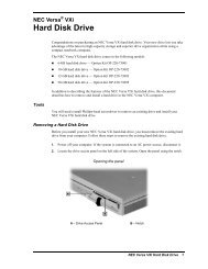
Removing the Hard Disk Drive .............................................................................4-8<br />
Keyboard ..............................................................................................................4-10<br />
LCD <strong>and</strong> Top Cover Assembly.............................................................................4-10<br />
Hinge covers..................................................................................................4-10<br />
Bottom Assembly..................................................................................................4-11<br />
Illustrated Parts Breakdown.........................................................................................4-12<br />
<strong>Service</strong> Information......................................................................................................4-16<br />
Technical <strong>Support</strong>........................................................................................................4-16<br />
Product Information.....................................................................................................4-17
vi<br />
Contents<br />
Ordering Information from Faxflash .............................................................................4-17<br />
Appendix A Connector Locations <strong>and</strong> Pin Assignments<br />
Appendix B<br />
Video Modes<br />
Index<br />
List of Figures<br />
1-1 NEC <strong>Versa</strong> <strong>5000</strong> Notebook ........................................................................... 1-1<br />
1-2 Location of Controls on the Front of the NEC <strong>Versa</strong> <strong>5000</strong>............................. 1-2<br />
1-3 LCD Status Bar <strong>and</strong> Button Locations ........................................................... 1-4<br />
1-4 Keyboard Layout ........................................................................................... 1-6<br />
1-5 <strong>Versa</strong>Glide Location ...................................................................................... 1-7<br />
1-6 Left Side Features.......................................................................................... 1-8<br />
1-7 Bottom of the System .................................................................................... 1-9<br />
1-8 Back system features...................................................................................... 1-9<br />
2-1 Connecting the AC Adapter ........................................................................... 2-1<br />
2-2 Power <strong>and</strong> I/O Connector Locations .............................................................. 2-3<br />
2-3 NEC <strong>Versa</strong> AC Adapter................................................................................. 2-4<br />
2-4 Batter Release Latches................................................................................... 2-7<br />
2-5 Sliding the Battery Release Latches................................................................ 2-8<br />
2-6 Removing the Battery Pack............................................................................ 2-8<br />
2-7 Installing the Battery Pack.............................................................................. 2-9<br />
2-8 Replacing the Latch........................................................................................ 2-10<br />
2-9 Power Button <strong>and</strong> Status LED Location ........................................................ 2-12<br />
2-10 Setup Main Menu........................................................................................... 2-19<br />
2-11 Password Override Switch ............................................................................. 2-27<br />
4-1 Releasing the Battery Pack............................................................................. 4-5<br />
4-2 Release Lever Cover ...................................................................................... 4-6<br />
4-3 Opening the Cover ......................................................................................... 4-6<br />
4-4 Pressing the Release Lever ............................................................................. 4-7<br />
4-5 Removing the Device ..................................................................................... 4-7<br />
4-6 Releasing the Spacer ...................................................................................... 4-8
Contents<br />
vii<br />
4-7 Sliding the Drive Towards the Spacer............................................................. 4-9<br />
4-8 Removing the Hard Drive............................................................................... 4-9<br />
4-9 Top Cover Subassembly................................................................................. 4-11<br />
4-10 NEC <strong>Versa</strong> Model <strong>5000</strong> Illustrated Parts Breakdown..................................... 4-15<br />
A-1 CPU Board Layout ........................................................................................ A-1<br />
A-2 I/O Board Layout........................................................................................... A-2<br />
List of Tables<br />
1-1 Model Configurations .................................................................................... 1-2<br />
1-2 Memory Map ................................................................................................. 1-13<br />
1-3 NEC <strong>Versa</strong> <strong>Series</strong> Chip Types <strong>and</strong> Technologies............................................ 1-15<br />
1-4 Interrupt Controllers ...................................................................................... 1-18<br />
1-5 Automatic Power-Saving Features ................................................................. 1-19<br />
1-6 Maximum Performance Default Settings......................................................... 1-21<br />
1-7 Specifications................................................................................................. 1-22<br />
2-1 I/O Connector Descriptions............................................................................ 2-3<br />
2-2 Control <strong>and</strong> Switch Functions ........................................................................ 2-12<br />
2-3 Fn Key Operations ......................................................................................... 2-14<br />
2-4 POST Error Messages.................................................................................... 2-17<br />
2-5 Setup Key Functions ...................................................................................... 2-20<br />
2-6 Setup Parameters ........................................................................................... 2-21<br />
2-7 Automatic Power-Saving Features ................................................................. 2-30<br />
3-1 Quick Troubleshooting................................................................................... 3-1<br />
4-1 NEC <strong>Versa</strong> <strong>5000</strong> <strong>Series</strong> Disassembly Sequence .............................................. 4-4<br />
4-2 Top Cover Components................................................................................. 4-12<br />
4-3 NEC <strong>Versa</strong> <strong>5000</strong> <strong>Series</strong> Field-Replaceable Parts............................................. 4-13<br />
4-4 NEC <strong>Service</strong> <strong>and</strong> Information Telephone Numbers......................................... 4-16<br />
A-1 CPU Board Connectors.................................................................................. A-2<br />
A-2 Top Cover Subassembly................................................................................. A-3<br />
A-3 Keyboard/Mouse Connectors......................................................................... A-3<br />
A-4 Serial Port Connector Pin Assignments .......................................................... A-3<br />
A-5 CRT Connector Pin Assignments ................................................................... A-4
viii<br />
Contents<br />
A-6 Parallel Printer Pin Assignments ..................................................................... A-4<br />
A-7 Power Connector ........................................................................................... A-5<br />
A-8 Hard Disk Drive Connector............................................................................ A-5<br />
B-1 LCD Display Mode Setting (800x600 TFT Color LCD <strong>and</strong><br />
Simultaneous CRT Display) ....................................................................... B-1<br />
B-2 LCD Display Mode Setting (800x600 TFT Color LCD <strong>and</strong><br />
Simultaneous CRT Display) ....................................................................... B-3<br />
B-3 Panning Video Mode (800x600 TFT Color LCD <strong>and</strong> Simultaneous<br />
CRT Display) .............................................................................................. B-4
Section 1<br />
Technical Information<br />
The NEC <strong>Versa</strong> <strong>5000</strong> <strong>Series</strong> notebook computer is lightweight, compact, <strong>and</strong> fully IBM<br />
compatible.<br />
NOTE<br />
This service manual covers only the NEC<br />
<strong>Versa</strong> 5060 <strong>and</strong> 5060X models. All figures in this<br />
manual reflect these models.<br />
Figure 1-1 NEC <strong>Versa</strong> <strong>5000</strong> <strong>Series</strong> Notebook<br />
This section of the manual provides system configuration information, including an overview<br />
of hardware <strong>and</strong> interface components. See the following table for a system-specific<br />
breakdown of the hardware.
1-2 Technical Information<br />
Table 1-1 Model Configurations<br />
Feature NEC <strong>Versa</strong> 5060 NEC <strong>Versa</strong> 5060X<br />
CPU Intel Pentium® with<br />
MMX technology<br />
P55CLM/166 MHz<br />
Intel Pentium® with<br />
MMX technology<br />
P55CLM/166 MHz<br />
On-Board DRAM 16-MB 16-MB + 16-MB<br />
installed in slot<br />
Video Memory 2-MB 2-MB<br />
Hard Disk Drive 1.6 GB 2.1 or 3.2 GB<br />
CD-ROM Reader 20X CD ROM Reader 20X CD ROM Reader<br />
Color LCD 12.1” Super VGA<br />
(SVGA),TFT Color<br />
Display<br />
13.3” Extended<br />
Graphics Array<br />
(XGA),TFT Color<br />
Display<br />
HARDWARE OVERVIEW—FRONT<br />
Take a moment to become familiar with the location <strong>and</strong> function of controls located on<br />
the front of the system.<br />
Figure 1-2 Location of Controls on the Front of the NEC <strong>Versa</strong> <strong>5000</strong>
Technical Information 1-3<br />
Liquid Crystal Display (LCD)<br />
The LCD operates with the NeoMagic NM2160 controller. The controller supports XGA<br />
<strong>and</strong> SVGA, uses a 64-bit accelerator with a Peripheral Component Interconnect (PCI) interface.<br />
The LCD also supports VESA timing.<br />
The NEC <strong>Versa</strong> 5060 LCD features the following:<br />
„ 12.1-inch Super Video Graphics Array (SVGA) TFT high-resolution active<br />
matrix SVGA color display<br />
„ 0.3075 mm dot pitch<br />
„ 18-bit digital interface<br />
„ 800 x 600 resolution<br />
„ 65,536 colors.<br />
The NEC <strong>Versa</strong> 5060X LCD features the following:<br />
„ 13.3-inch Extended Graphics Array (XGA) TFT high-resolution active matrix<br />
XGA color display<br />
„ 0.264 mm dot pitch<br />
„ 18-bit digital interface with LVDS<br />
„ 1024 x 768 resolution<br />
„ 65,536 colors.<br />
Additional LCD panel features:<br />
Power LED that indicates the current power status. This LED is visible with the LCD<br />
panel opened or closed.<br />
Another video feature includes a CRT port on the system's rear panel that allows the user<br />
to connect an optional monochrome or color external display to the system. The computer<br />
can support the LCD <strong>and</strong> external display simultaneously.<br />
Power-saving features for controlling the LCD's backlighting include the ROM-based hot<br />
key combination Fn F5, <strong>and</strong> Auto Setup power management settings. See Section 2, Setup<br />
<strong>and</strong> Operation, for information on using these settings. In addition, the automatic LCD<br />
status feature conserves the backlight.
1-4 Technical Information<br />
Power Button <strong>and</strong> Status LEDs<br />
NEC <strong>Versa</strong> provides a Power button <strong>and</strong> LEDs to track system status. Descriptions of<br />
these features follow the figure.<br />
Figure 1-3 LCD Status Bar <strong>and</strong> Button Locations<br />
„ Power Button — The Power button is located on the chassis just below the<br />
LCD. It turns NEC <strong>Versa</strong> <strong>5000</strong> power on <strong>and</strong> off. Press the button to turn<br />
power on; press it again to turn power off.<br />
⎯ When power is on, the Power LED to the right of the Power button<br />
lights. (The Power LED is the left-most LED in the row of LEDs.)<br />
See “Setup Parameters” in Section 2 for information about defining<br />
this button as a Suspend/Resume button.<br />
⎯ If your system is in Suspend mode or has gone into Save to Disk<br />
mode, pressing the Power button puts the system in Operation mode.<br />
NOTE<br />
After turning off the system, wait 5 seconds<br />
before turning it back on. This gives system components<br />
a chance to power down properly.
Technical Information 1-5<br />
„ The Battery/Charging Status LED is located on the right-h<strong>and</strong> LCD<br />
hinge <strong>and</strong> lights to indicate the following:<br />
⎯ Green – the battery is fully charged <strong>and</strong> the system is connected to<br />
AC power.<br />
⎯ Amber – the battery is recharging.<br />
⎯ Off – the AC adapter is disconnected or the battery is not installed.<br />
„ A bank of status LEDs is located on the chassis at the top of the keyboard<br />
to the right of the Power button. These LEDs are identified by<br />
icons <strong>and</strong> include the following (described from left to right):<br />
⎯ The Power LED lights in the following sequence to indicate system<br />
operation status.<br />
– lights green when running on AC power.<br />
– blinks green when the system is in Suspend mode.<br />
– lights amber when running on battery power with<br />
a charged battery.<br />
The Power LED also warns you about a low battery state. The<br />
system emits a beep <strong>and</strong> the Power LED behaves as follows:<br />
– blinks amber when battery power is low.<br />
– flashes amber when battery power is extremely<br />
low.<br />
The Power LED remains unlit under the following conditions:<br />
– if the system is not connected to AC power <strong>and</strong><br />
the battery is not charged or installed.<br />
– the system is not powered on.<br />
– the system is in Save to Disk mode.<br />
⎯ Hard Disk Drive – Lights when the NEC <strong>Versa</strong> <strong>5000</strong> writes data to<br />
or retrieves data from the hard disk drive.<br />
⎯ CD-ROM Reader – Lights when data is read from a compact disc in<br />
the CD-ROM drive.<br />
⎯ Diskette Drive – Lights when data is written to or retrieved from the<br />
3.5-inch diskette drive.<br />
⎯ Caps Lock – Lights when Caps Lock is on.<br />
⎯ Num Lock – Lights when Num Lock mode is active.
1-6 Technical Information<br />
Keyboard<br />
⎯ Scroll Lock – Lights when the Scroll Lock is on.<br />
The built-in, 85-key keyboard (U.S.) or 79-key keyboard (UK <strong>and</strong> Germany) uses the<br />
st<strong>and</strong>ard QWERTY format. The keyboard provides 12 function keys <strong>and</strong> 7 cursor control<br />
keys, with an Fn key for ROM-based key functions. The numeric keypad is embedded in<br />
the st<strong>and</strong>ard key layout.<br />
Figure 1-4<br />
Keyboard Layout<br />
NEC <strong>Versa</strong>Glide<br />
The NEC <strong>Versa</strong>Glide is a built-in mechanism that functions as the system’s mouse. It controls<br />
the on-screen pointer (cursor). To use the <strong>Versa</strong>Glide, move your finger across the<br />
NEC <strong>Versa</strong>Glide pad, <strong>and</strong> the cursor follows. The buttons below the NEC <strong>Versa</strong>Glide allow<br />
the user to select or deselect menu items. Tap <strong>and</strong> double-tap are supported on the<br />
<strong>Versa</strong>Glide pad.
Technical Information 1-7<br />
Figure 1-5<br />
<strong>Versa</strong>Glide Location<br />
UltraSlim <strong>Versa</strong>Bay<br />
A st<strong>and</strong>ard 1.44-MB diskette drive comes installed in the UltraSlim <strong>Versa</strong>Bay slot on the<br />
front of the computer. The UltraSlim <strong>Versa</strong>Bay expansion slot lets the user replace the<br />
st<strong>and</strong>ard diskette drive with the 20X CD-ROM reader that also ships with the system. In<br />
addition to the CD-ROM reader, the UltraSlim <strong>Versa</strong>Bay accepts NEC options including a<br />
Weight Saving Module.<br />
HARDWARE OVERVIEW—SIDES OF THE SYSTEM<br />
Your NEC <strong>Versa</strong> <strong>5000</strong> comes with many features on the left side of the system. The right<br />
side of the system features a port for securing the PortBar <strong>and</strong> air vents. Keep the air vents<br />
clear to allow for proper air circulation.<br />
! CAUTION<br />
Do not block the air vents. Doing so can damage the<br />
system by causing it to overheat.
1-8 Technical Information<br />
The features found on the left side of the system are shown in the following figure.<br />
Descriptions follow the figure.<br />
Figure 1-6 Left side features<br />
„ PC Card Release Buttons — Press the Release button when you want to<br />
remove an installed PC card.<br />
„ Audio Ports — Use these ports to attach your external audio options, including<br />
the following:<br />
⎯ Microphone — Connects to an external microphone for monophonic<br />
recording or amplification through the unit. Plugging in an external<br />
microphone disables the built-in microphone.<br />
⎯ Stereo Line In — Lets you use another audio system, like a home<br />
stereo, as an input source. Use a cable to connect to the Line-Out port<br />
on the other audio system to record or play.<br />
⎯ Headphones — Lets you plug in stereo headphones or powered<br />
speakers.<br />
„ Volume Control Dial — Turn the volume control dial clockwise to increase<br />
speaker volume, or counter-clockwise to decrease speaker volume.<br />
„ Kensington Lock Port — Use this port for added security by attaching a<br />
Kensington Lock.<br />
„ Emergency Reset Switch — This recessed switch lets you restart your<br />
system. Use a pointed object, like a straightened paper clip, to push in<br />
the Reset switch. Do not use a pen or pencil to push the reset switch.<br />
Use this button only if your system locks up, fails to respond to keystrokes,<br />
or fails to respond to the power button.<br />
„ PC Card Slots — Two PC card slots let you insert one or two Type II PC<br />
cards, or one Type III PC card.
Technical Information 1-9<br />
„ PortBar Port — Use these ports to secure the PortBar. A matching Port-<br />
Bar port is located on the right side of the system. Two others are located<br />
on the back.<br />
Around the Bottom of the System<br />
The bottom of the NEC <strong>Versa</strong> <strong>5000</strong> is the location of the system’s memory module sockets,<br />
password override switch, battery pack release latches, <strong>Versa</strong>Bay release lever <strong>and</strong><br />
hard disk drive bay, as described next.<br />
Figure 1-7 Bottom of the system<br />
„ Password Override Switch — This recessed switch removes any settings<br />
that you made in the Setup utility, including your system password.<br />
To remove your password, power on your system. Use a pointed object,<br />
such as a straightened paper clip, to push in the switch. Power off, <strong>and</strong><br />
then power on to restart your computer. Go into the Setup utility <strong>and</strong> set<br />
a new password. Reset any other system settings that you may have<br />
changed.<br />
„ <strong>Versa</strong>Bay Release Lever Cover — Open the release lever cover to access<br />
the <strong>Versa</strong>Bay Release Lever. Pushing the lever towards the front of the<br />
system releases the device currently installed in the <strong>Versa</strong>Bay.
1-10 Technical Information<br />
NOTE<br />
Opening the <strong>Versa</strong>Bay Release Lever Cover<br />
immediately puts the system into Suspend mode.<br />
After installing the <strong>Versa</strong>Bay device, press the<br />
Power button to resume the system from Suspend.<br />
„ Battery Pack — A Lithium-Ion (Li-Ion) rechargeable battery pack comes<br />
installed in this bay on the bottom of the NEC <strong>Versa</strong>.<br />
„ Battery Release Latches — Lets you remove the battery pack installed in<br />
the battery bay.<br />
„ Memory Expansion Bay Cover — Pop open the protective cover to access<br />
two RAM expansion sockets for small outline double inline memory<br />
modules (SO-DIMM).<br />
„ Hard Disk Drive — A removable hard disk drive ships st<strong>and</strong>ard with<br />
your system <strong>and</strong> is located on the bottom of the unit. Depending on your<br />
configuration, this bay contains a 1.6-, 2- or 3-gigabyte (GB) hard disk<br />
drive. (Chapter 4 describes how to remove this drive.)<br />
The drive letter assigned to 1.6-GB <strong>and</strong> 2-GB hard drives is C:. If your<br />
system ships with a 3-GB drive, it is partitioned into two drives. Drive<br />
letters are C: <strong>and</strong> D:.<br />
Around the Back of the System<br />
System ports for connecting your NEC <strong>Versa</strong> <strong>5000</strong> to optional devices (like a printer or<br />
external monitor) are located on the back of the system. For an underst<strong>and</strong>ing of each feature,<br />
see the descriptions that follow the figure.<br />
Figure 1-8 Back system features
Technical Information 1-11<br />
„ Keyboard/Mouse Port — Use the st<strong>and</strong>ard PS/2 port to connect an external<br />
PS/2-style mouse or a PS/2-style keyboard to the system.<br />
„ <strong>Support</strong> Feet — Slide the two support feet down from the back of the<br />
unit to tilt your system forward for more comfortable keyboard access.<br />
„ Infrared (IR) Port — Use this port to transfer files between your NEC<br />
<strong>Versa</strong> <strong>and</strong> an IR-equipped desktop or notebook computer. You can also<br />
print to an IR-equipped printer without using cables.<br />
„ Expansion Port — Use this 120-pin port to connect to the NEC PortBar<br />
<strong>5000</strong>.<br />
„ Monitor (Video) Port — Use this 15-pin port to attach an external<br />
monitor to your NEC <strong>Versa</strong> <strong>5000</strong>. You can run the LCD display <strong>and</strong> the<br />
external monitor simultaneously or run either alone.<br />
„ USB Port — Use this port to connect a USB device or devices to your<br />
NEC <strong>Versa</strong> system.<br />
„ PortBar Ports — Use these ports to secure the optional PortBar. PortBar<br />
ports are located on the back <strong>and</strong> sides of the system at each end.<br />
„ External Diskette Drive Connector — Connect the External Diskette<br />
Drive cable that came with your system to this port. Using the FDD connector<br />
frees up the <strong>Versa</strong>Bay for installing the 20X CD-ROM reader.<br />
„ Parallel Port — Use this 25-pin port to connect a parallel printer or other<br />
parallel device. This port provides ECP mode support. The ECP st<strong>and</strong>ard<br />
provides you with a greater transfer speed than the conventional parallel<br />
port. It also supports bi-directional <strong>and</strong> uni-directional protocols.<br />
„ Serial Port — Use this 9-pin port to connect an external modem or other<br />
serial device.<br />
„ AC Power Port — Lets you attach the NEC <strong>Versa</strong> <strong>5000</strong> to the AC power<br />
source using the AC adapter that comes with your system. Keep the system<br />
connected to AC power whenever possible to keep the battery pack<br />
<strong>and</strong> internal CMOS battery charged.<br />
HARDWARE OVERVIEW—INTERNAL COMPONENTS<br />
Review the following sections for a description of the system’s internal hardware.<br />
Battery Pack<br />
The system uses a rechargeable Lithium-Ion (Li-Ion) battery as its transient power source.<br />
The battery pack installs in the compartment next to the UltraSlim <strong>Versa</strong>Bay on the bottom<br />
of the NEC <strong>Versa</strong>.
1-12 Technical Information<br />
Hard Disk Drive<br />
A st<strong>and</strong>ard 2.5-inch 1.6-GB 9.5 mm, 2.1-GB 12.7 mm or 3.2-GB 12.7 mm hard disk drive<br />
ships with the system.<br />
Diskette Drive<br />
The interchangeable 3.5-inch 1.44 MB diskette drive installs in the front of the system in<br />
the UltraSlim <strong>Versa</strong>Bay slot.<br />
20X CD-ROM Reader<br />
A 20X CD-ROM reader ships with the NEC <strong>Versa</strong> <strong>5000</strong>. The interchangeable twentyspeed<br />
CD-ROM reader features the latest in CD-ROM technology. It installs in the front of<br />
the system in the UltraSlim <strong>Versa</strong>Bay slot.<br />
CPU Board<br />
The CPU board is located between the Main board <strong>and</strong> Fan/Heat Sink assembly. The CPU<br />
board is part of a subassembly, which includes a heat sink, fan <strong>and</strong> the CPU board.<br />
Audio Board<br />
The audio board provides the NEC <strong>Versa</strong> system with its audio capabilities via line-in/lineout<br />
jacks, <strong>and</strong> headphone/microphone jacks. It is situated on top of the main board. Audio<br />
board integrates the following features:<br />
Main Board<br />
⎯ ESS Technology Plug <strong>and</strong> Play support<br />
⎯ ES1869A<br />
⎯ Integrated Music Synthesis, ESFM <strong>and</strong> Stereo Digital to Analog Converter<br />
(DAC) FM Synthesizer<br />
⎯ 16 bit Stereo CODEC<br />
⎯ 4.0KHz to 44.1KHz Sampling Rate<br />
⎯ 7 Channel Mixer.<br />
The system Main board contains peripheral subsystems including serial, parallel <strong>and</strong> video<br />
ports, <strong>and</strong> CPU. It is located underneath the keyboard. Refer to Appendix A for a list of<br />
connectors.
Technical Information 1-13<br />
Bridge Battery<br />
The bridge battery saves the memory contents <strong>and</strong> system status for up to 5 minutes while<br />
in Suspend mode. It is connected to the Audio board via connector P11. The AC adapter<br />
maintains voltage in the bridge battery when the system is powered on or off. The bridge<br />
battery stores 3.6 Volts, 70 mAH.<br />
SYSTEM MEMORY<br />
The CPU board provides 16 MB (3.3 V SO-DIMM) of st<strong>and</strong>ard RAM.<br />
Optional SO-DIMMs with a value of 16-MB, 32-MB <strong>and</strong> 64 MB can be added to increase system<br />
memory <strong>Versa</strong> 5060/5060X: Maximum 80-MB, <strong>Versa</strong> 5080/5080X: Maximum 144-MB.<br />
In addition, 256-KB of read-only memory (ROM), 1 x 28F020, enables the system BIOS to be flashed.<br />
The system provides 2 MB of video RAM (50-ns HyperPage mode, self-refresh).<br />
The following Cache RAM is provided:<br />
L1: 32 KB (Internal Pentium)<br />
L2: 256 KB write back (External).<br />
Memory Map<br />
The system supports system <strong>and</strong> video shadowing, both controlled through complementary<br />
metal oxide semiconductor (CMOS). The system supports BIOS as a cacheable area with<br />
write protection. Table 1-2 lists the system's memory map.<br />
Table 1-2<br />
Memory Map<br />
Memory Space Size Function<br />
0000000h-009FFFFh 640 KB DOS Applications & Optional Memory<br />
Space Gap<br />
00A0000h-00B7FFFh 96 KB Video (VGA) Graphics Memory<br />
00B8000h-00BFFFFh 32 KB Text Mode Memory (SMM Space)<br />
00C0000h-00C7FFFh 40 KB Video (VGA) BIOS<br />
00C8000h-00D7FFFh 128 KB PCMCIA Window <strong>and</strong> USB (Extended<br />
Memory or Upper Memory Block)<br />
00D8000h-00DFFFFh 32 KB Boot Block Code CMOS Save Area<br />
00E0000h-000FFFFFh 64 KB System BIOS ROM<br />
To -00FFFFFFh 16 MB Total Base Memory<br />
To -FFFEFFFFh 80 MB Total Expansion Memory
1-14 Technical Information<br />
SYSTEM VIDEO<br />
The system's LCD operates using the NeoMagic NM2160 Controller. Video signals travel<br />
from the controller through the system's 15-pin D-SUB connector using 3.3/5 volts.<br />
System video integrates a PCI-bus interface. The system ships with 2 MB Video RAM<br />
(VRAM). It supports video modes up to 1024 x 768 with 64K colors in LCD mode.<br />
See Appendix B for a list of Video modes.<br />
PARALLEL INTERFACE<br />
The system' s parallel interface integrates National Semiconductor’s PC87338 chip with a<br />
25-pin D-subconnector. The port is located on the system's rear panel.<br />
The modes of operation available for a PC87338 chip are:<br />
„ compatibility mode<br />
„ nibble mode<br />
„ byte mode<br />
„ Extended Capabilities Port (ECP)<br />
The user selects between three parallel interface modes using Auto Setup. These include<br />
unidirectional, bidirectional, extended or enhanced. Unidirectional mode sends data output<br />
from the st<strong>and</strong>ard ISA port only. Bidirectional mode sends data using the st<strong>and</strong>ard ISA<br />
port or PS/2 technology. Enhanced mode enables high speed data transmission to occur<br />
using either the unidirectional or bidirectional modes.<br />
The default parallel port address is 378h <strong>and</strong> the interrupt level is IRQ07. Pin locations for<br />
the parallel interface are listed in Appendix A.<br />
SERIAL INTERFACE<br />
The RS-232C serial port is a 9-pin connector on the system’s rear panel. The serial port<br />
consists of a 16550A <strong>and</strong> 16450 compatible serial port controller with a programmable<br />
baud rate up to 115,200 bps. The serial port connects an RS-232C device or an external<br />
modem. The default serial port address is 3F8h <strong>and</strong> the interrupt level is IRQ04.
Technical Information 1-15<br />
NEC VERSA CHIP SET<br />
Refer to Table 1-3 for a quick summary of chip types used in the system. See the Abbreviations<br />
section at the beginning of this manual for a translation of chip technologies.<br />
Table 1-3 NEC <strong>Versa</strong> <strong>Series</strong> Chip Types <strong>and</strong> Technologies<br />
Chip Manufacturer Description Technology<br />
Intel Pentium<br />
P55CTT80503<br />
Intel 166 MHz CPU 320-pin TCP<br />
82C700(FireStar) Opti FireStar System Controller 432--pin BGA<br />
82C861(FireLink) Opti USB Controller 100-pin TQFP<br />
N28F002BC-90 Intel 256k x 8 Flash ROM 32-pin PLCC<br />
NM2160 NeoMagic VGA Controller 208-pin FQFP<br />
PC97338 National<br />
Semiconductor<br />
Diskette Controller, IDE,<br />
Parallel Interface<br />
100-pin TQFP<br />
H8/3434 Hitachi Keyboard Controller 64-pin TQFP<br />
PCI1131 Texas Instruments PC Card Controller 208-pin QFP<br />
ES1869 ESS Technologies Sound Controller 100-pin PQFP<br />
Intel Pentium P55CLM Microprocessor<br />
The 166 MHz Intel Pentium microprocessors with MMX technology used in the NEC<br />
<strong>Versa</strong> <strong>Series</strong> computer is built on Intel’s advanced 2.5V BiCMOS silicon technology. The<br />
CPU has on-chip dual-processing, a local multiprocessor interrupt controller, <strong>and</strong> power<br />
management features. NEC adopted the chip specifically for its pipelined Floating Point<br />
Unit (FPU), <strong>and</strong> local interrupt management.<br />
FireStar System Controllers<br />
NEC implements Opti’s 64-bit single chip controller (82C700) for the NEC <strong>Versa</strong> <strong>5000</strong><br />
<strong>Series</strong> notebook’s subsystems including the DRAM controller, Second Level Cache Controller<br />
<strong>and</strong> PCI Bus interface. The FireStar PCI set features include:<br />
USB Controller<br />
„ 3.3V EDO DIMM (70-ns) support<br />
„ direct mapped organization write-back policy<br />
„ fully synchronous 33 MHz PCI bus interface.<br />
The Opti 82C861 FireStar chip is a PCI USB controller. The controller based on Open HCI<br />
st<strong>and</strong>ard <strong>and</strong> supports hot plug in <strong>and</strong> unplug.
1-16 Technical Information<br />
The chip features include:<br />
„ USB Specification Rev 1.0<br />
„ Open HCI Specification Rev 1.0a.<br />
256K X Flash ROM<br />
The N28F002BC-90 flash ROM is a 32-pin, plastic lead chip carrier (PLCC). The chip allows<br />
easy updates to the system's BIOS if needed. More specifically, the ROM is flashed<br />
electronically, installing the latest BIOS revisions to the system. It is possible to reprogram<br />
the BIOS up to 100,000 times. See Section 2, Setup <strong>and</strong> Operation, for BIOS update procedures.<br />
The N28F002BC-90 provides the system upgrade capability as well as the following:<br />
„ 256 KB memory<br />
„ Quick-Pulse Programming Algorithm<br />
„ 150 nanoseconds (ns) maximum access time<br />
„ ETOX Nonvolatile flash technology<br />
„ CMOS low power consumption<br />
ROM BIOS<br />
The system uses a Flash ROM known as the system's ROM BIOS to store machine language<br />
programs. The BIOS size is 256 KB, consisting of the system utility (for PC cards,<br />
Auto Setup), system BIOS, video BIOS, <strong>and</strong> power management.<br />
The BIOS programs execute the power-on self-test (POST), initialize CPU controllers, <strong>and</strong><br />
interact with the LCD indicator panel, diskette drive, hard drive, communication devices<br />
<strong>and</strong> peripherals. The system BIOS also contains Auto Setup <strong>and</strong> provides VGA controller<br />
support. The ROM BIOS is copied into RAM (shadowing) for optimum performance.<br />
The ROM BIOS contains both the system <strong>and</strong> video BIOS. The system BIOS is located in<br />
the upper portion of the device; video BIOS is located in the lower portion. System BIOS<br />
is located between 00F0000h-000FFFFFh.<br />
The BIOS often changes after the product release to provide enhanced features or bug<br />
fixes. To acquire the latest BIOS release, the ROM is flashed electronically allowing the<br />
BIOS update to occur without removing the ROM. See Section 2, Setup <strong>and</strong> Operation, for<br />
BIOS upgrade procedures.
Technical Information 1-17<br />
VGA Controller<br />
The NeoMagic NM2160 is a PCI 128-bit Graphics Accelerator. The integrated programmable<br />
linear address feature accelerates the graphics user interface (GUI) performance.<br />
The controller also supports Hardware Multimedia <strong>and</strong> VESA interface st<strong>and</strong>ards. The<br />
controller provides advanced power management that helps to minimize power usage in<br />
the following modes:<br />
„ normal operation<br />
„ St<strong>and</strong>by (sleep) mode<br />
„ panel off power saving modes.<br />
Parallel Interface<br />
The PC87338VJG chip is a 100-pin Thin Quad Flat Plastic (TQFP) chip. The controller<br />
changes 8-bit parallel data into serial data <strong>and</strong> writes the data to the diskette. Conversely,<br />
the serial data is transmitted from the diskette into parallel data, where it remains until the<br />
read operation takes place.<br />
„ Additional PC87338VJG chip operations include:<br />
„ ISA compatibility<br />
„ low-power CMOS with enhanced power-down mode<br />
Keyboard Controller<br />
The keyboard controller (H8/3434) supports a PS/2-style keyboard <strong>and</strong>, mouse. Refer to<br />
Appendix A for keyboard interface connector pin assignments.<br />
When data is written to the output buffer, the controller generates an interrupt, <strong>and</strong> requests<br />
the CPU to receive the data. The controller automatically adds an even parity bit to the data<br />
sent <strong>and</strong> waits for a response. The device must acknowledge that the data was successfully<br />
received by sending a response to the controller for each byte of data received.<br />
PC CardBus Controller<br />
The Texas Instruments PCI1131 controller interfaces with the PCI bus, PC CardBus socket<br />
<strong>and</strong> configuration registers to provide:<br />
„ compliant with PCI 2.1 <strong>and</strong> 1995 PC card st<strong>and</strong>ards<br />
„ CardBus slots with hot insertion <strong>and</strong> removal<br />
„ independent Read <strong>and</strong> Write buffers for each direction<br />
„ burst transfers to maximize data throughput on the PCI CardBus bus.
1-18 Technical Information<br />
Sound Integrated Circuit<br />
The ESS Technologies chip set ES1869A provides dynamic audio circuitry with the following:<br />
„ Audio digital processor<br />
„ Plug <strong>and</strong> Play support<br />
„ High-performance 16-bit Stereo Codec<br />
„ Full-duplex operation for simultaneous record <strong>and</strong> playback<br />
„ Analog joystick quad timer <strong>and</strong> digital joystick support.<br />
Interrupt Controllers<br />
Using interrupts, it is possible to change the system’s code sequence. To change the sequence,<br />
reassign the interrupt-levels. Fifteen interrupts can be used with a cascade connection<br />
of two 82C59 interrupt controllers.<br />
Interrupt-level assignments 0 through 15 are listed in Table 1-4, in order of decreasing<br />
priority.<br />
Table 1-4 Interrupt Controllers<br />
Channel Device<br />
IRQ00 System Timer<br />
IRQ01 Keyboard<br />
IRQ02 Second Interrupt Controller<br />
IRQ03 COM2 (internal IR port)<br />
IRQ04 COM1 (internal serial port)<br />
IRQ05 Sound Chip, MIDI (default)<br />
IRQ06 Floppy Disk Drive Controller<br />
IRQ07 LPT1 Default (internal printer port)<br />
IRQ08 Real Time Clock<br />
IRQ09 USB<br />
IRQ10 Not Used<br />
IRQ11 CardBus controller<br />
IRQ12 Internal Glide Pointer or External<br />
PS/2 Mouse<br />
IRQ13 Co-Processor<br />
IRQ14 Primary IDE (Hard Disk Drive)<br />
IRQ15 Secondary IDE (CD-ROM)
Technical Information 1-19<br />
POWER MANAGEMENT OVERVIEW<br />
Power Management in the NEC <strong>Versa</strong> lets you conserve energy, save battery power, extend<br />
the life of your LCD backlight, <strong>and</strong> protect against data loss due to low battery power.<br />
Set some features to function automatically or activate them manually with the keyboard or<br />
a button. It is wise to keep Power Management features enabled, even when using AC<br />
power.<br />
The system ships with many power-saving features already enabled. See the following table.<br />
Device<br />
Table 1-5 Automatic Power-Saving Features<br />
Default<br />
Timeout<br />
Comment<br />
Idle Mode On Idle mode slows down the CPU during brief<br />
periods when the system is not busy.<br />
St<strong>and</strong>by Timeout 4 minutes Specifies how long the system is in Idle mode<br />
before entering St<strong>and</strong>by mode. St<strong>and</strong>by turns off<br />
various system devices including the screen.<br />
Auto Suspend<br />
Timeout<br />
10 minutes This setting specifies how long the system<br />
remains in St<strong>and</strong>by mode before entering<br />
Suspend.<br />
Hard Disk Timeout 2 minutes Stops the hard disk motor when the hard disk is<br />
not accessed for the specified timeout.<br />
Video Timeout 2 minutes Shuts off video screen after the timeout specified<br />
elapses.<br />
CD-ROM Timeout 45 seconds Specifies how long the CD-ROM reader remains<br />
inactive before being turned off.<br />
NOTE<br />
In Windows 95 systems, power management<br />
settings under Windows override the settings established<br />
in Setup.<br />
You can change the timeout period for any of the devices using Setup. See Section 2 for<br />
Setup utility procedures.<br />
Use the FnF7 key combination to set the power management level you can toggle between<br />
Highest Performance, Longest Battery Life, Custom Power Management, <strong>and</strong> Off. Default<br />
values change depending on the type of power management you use.
1-20 Technical Information<br />
System Power Management<br />
NEC <strong>Versa</strong> system power management consists of the following operation modes. These<br />
modes are:<br />
„ Active Mode • In active mode, the system uses no power management. It<br />
operates with the default clock speed. The system continues to run at this<br />
speed unless overwritten by the power management features.<br />
„ St<strong>and</strong>by Mode • The system switches automatically to St<strong>and</strong>by mode.<br />
This eliminates unnecessary power consumption when you operate the<br />
system on battery power or AC. St<strong>and</strong>by mode shuts down the LCD<br />
panel, providing privacy as well as power savings.<br />
„ Suspend Mode • Suspend mode causes the CPU to power down, local<br />
devices to shut down, <strong>and</strong> register values to be stored in RAM. System<br />
RAM is put into a slow refresh state.<br />
The system resumes Active mode when you press the Suspend button, or the system is set<br />
to resume at a certain time of day. Suspend mode lets you save power without first saving<br />
the working data.<br />
Press the Fn-Esc keys simultaneously to enter Suspend mode when you need to be away<br />
from the system for a short period of time <strong>and</strong> want to return to where you left off.<br />
In addition, to quickly activate the Save to File feature, press the Fn-Power Button<br />
buttons simultaneously. This shuts down the system, <strong>and</strong> saves the current working data to<br />
a file.<br />
Local Power Management<br />
Use Auto Setup to select one of four power management settings for local devices. These<br />
include Longest Life, Maximum Performance, Customize, <strong>and</strong> Power Management Off.<br />
The power management levels are also available during AC operation. The NEC <strong>Versa</strong><br />
computer ships with Longest Life as the default power management setting. See Section 2<br />
for specific procedures on using Auto Setup to select the power management settings.<br />
When set to Longest Life, CMOS will set local device timeout values, a local st<strong>and</strong>by<br />
timeout value, <strong>and</strong> a suspend timeout value to ensure the longest battery life. The Maximum<br />
Performance setting selects CMOS values that will provide minimal energy savings<br />
<strong>and</strong> a shorter battery life. The customize settings enable end-users to set the timeout values<br />
of their choice. The Power Management Off selection terminates all power management<br />
timers.<br />
Local device timers in the system control power consumption in the LCD <strong>and</strong> Hard Disk<br />
Drive. Table 1-6 shows NEC <strong>Versa</strong> <strong>Series</strong> Maximum Performance default power management<br />
timers.
Technical Information 1-21<br />
Table 1-6 Maximum Performance Default Settings<br />
Power<br />
Management Mode<br />
Automatic<br />
Suspend Hard Disk Timer Video Timeout<br />
Longest Life 10 minutes 2 minutes 2 minutes<br />
Maximum Performance 30 minutes 2 minutes 6 minutes<br />
Custom 10 minutes 2 minutes 2 minutes<br />
PLUG AND PLAY<br />
The NEC <strong>Versa</strong> features Plug <strong>and</strong> Play functionality. Plug <strong>and</strong> Play is the ability of the<br />
BIOS <strong>and</strong>/or operating system to dynamically assign system resources to a newly installed<br />
device without user intervention.<br />
For example, you can suspend the system, add a monitor or device to the <strong>Versa</strong>Bay, <strong>and</strong><br />
when you resume working, the NEC <strong>Versa</strong> recognizes the devices that have been connected<br />
to it. Similarly, you can remove external devices in Suspend mode <strong>and</strong> the NEC<br />
<strong>Versa</strong> detects the status when resumed.<br />
The NEC <strong>Versa</strong> is capable of having a keyboard or mouse added or removed while in the<br />
Power On mode. This capability is known a Hot Swap. Changes made while in Suspend<br />
Mode are classified as a Warm Swap.
1-22 Technical Information<br />
SPECIFICATIONS<br />
Table 1-7 provides a complete list of NEC <strong>Versa</strong> <strong>Series</strong> system specifications.<br />
Item Specification<br />
Table 1-7 Specifications<br />
Chassis Configuration<br />
Size Width: 12.0 in. (306 mm)<br />
Depth: 9.6 in. (243 mm)<br />
Height: 1.5 in. (38 mm)<br />
Weight: 4.9 lb (2.23 kg) with Weight Saving Module<br />
5.3 lb (2.4 kg) with FDD<br />
5.5 lb (2.5 kg) with CD-ROM<br />
Exact weight depends on options<br />
Keyboard PS/2 compatible, 85-key (both U.S. <strong>and</strong> International) with<br />
QWERTY-key layout (International keyboards are countryspecific)<br />
Device Slots Two PC Card slots that support up to two optional cardsoriented<br />
one on top of the other<br />
One 3 1/2-inch x 0.75-inch high slot, front access, for st<strong>and</strong>ard<br />
1.44 diskette drive, optical diskette drive 120 MB or 20X CD-<br />
ROM reader.<br />
Power 100 to 240 Volts AC at 50 or 60 Hz<br />
Output Voltage — 19 V DC, 2.6 A (49.4 W)<br />
Battery Pack Weight ⎯ .99 lb (.51 Kg)<br />
Voltage ⎯ 14.4 V<br />
Capacity ⎯ 2400 mAH<br />
Front Panel Controls Power Button<br />
Battery Life ⎯ Approximately 1.5 to 3 hours (depending on<br />
model <strong>and</strong> power management settings)<br />
LEDs Battery/Charging Status LEDs<br />
Recharging Time ⎯ Approximately 3 hours when the system is<br />
on or off<br />
Bridge Battery ⎯ Backs up memory contents up to 5 minutes in<br />
Suspend mode<br />
Status LEDs ⎯ Power, Hard Disk Drive, CD-ROM Reader,<br />
Diskette Drive, Caps Lock, Number Lock <strong>and</strong> Scroll Lock.
Technical Information 1-23<br />
Item Specification<br />
Table 1-7 Specifications (cont’d)<br />
System Board<br />
CPU Intel Pentium 166 MHz<br />
Clock Speed 166 MHz<br />
CPU Bus Speed 66 MHz<br />
Flash ROM 256 KB: 28F002<br />
Connector <strong>Support</strong> Parallel —1 port, 25-pin D-sub<br />
Serial — 1 port, 9-pin D-sub<br />
Infrared — 1 on back of system<br />
VGA — 1 port, 15-pin high-density D-sub<br />
External Keyboard/External Mouse — 1 port, PS/2, 6-pin<br />
MiniDin; exclusionary use or both supported with optional<br />
Y-adapter<br />
Expansion — 1 port, 120-pin for optional PortBar <strong>5000</strong><br />
Mono MIC IN — 1 port, 3-pin, Mini Pin Jack<br />
Stereo Headphones/Line-Out — 1 port, 3-pin, Mini Pin Jack, .5<br />
watts per channel<br />
Stereo Line-In — 1 port, 3-pin, Mini Pin Jack<br />
USB Port — 1 port, 4 pin<br />
External Diskette Drive ⎯ 1 port for the external connection of<br />
the diskette drive, 26 pin<br />
DC In — 1 port, for AC adapter cable<br />
Memory<br />
System Memory 16 or 32 MB high-speed EDO access 60 ns<br />
Optional Two so-DIMM sockets (for expansion memory<br />
Video RAM 2 MB<br />
Exp<strong>and</strong>able in 16-MB, 32-MB increments<br />
Maximum 80-MB (by adding 2 so-DIMM of 32-MB)<br />
Video Interface (VGA)<br />
LCD NEC <strong>Versa</strong> 5060 12.1-inch high-resolution active matrix Thin Film Transistor<br />
(TFT) Super VGA (SVGA) color display, 800 x 600 pixels,<br />
0.3075 mm dot pitch, 65,536 colors<br />
LCD NEC <strong>Versa</strong> 5060X 13.3-inch high-resolution active matrix Thin Film Transistor<br />
(TFT) Extended Graphics Array (XGA) color display, 1024 x<br />
768 pixels, 0.264 mm dot pitch, 256,000 colors
1-24 Technical Information<br />
Item Specification<br />
Table 1-7 Specifications (cont’d)<br />
Internal Device <strong>Support</strong><br />
Diskette Drive User-removable 3 1/2-inch, 1.44-MB, installs in UltraSlim<br />
<strong>Versa</strong>Bay slot or connects to the external FDD connector<br />
Hard Disk Drives IDE interface (built-in), System ships with a 1.6, 2.1 or 3.2-GB<br />
hard disk drive<br />
20X CD-ROM Reader User-removable twenty-speed (20X) CD-ROM reader, installs<br />
in UltraSlim <strong>Versa</strong>Bay slot<br />
External Device <strong>Support</strong><br />
CRT Displays up to 1280 x 1024 resolution x 256 colors<br />
Mouse PS/2-compatible mouse<br />
Keyboard Built-in 85 key keyboard with 12 programmable function keys,<br />
embedded numeric keypad <strong>and</strong> special function control keys,<br />
dedicated screen control keys, <strong>and</strong> inverted “T” cursor keys /<br />
IBM enhanced 101/102-key compatible keyboard<br />
Software<br />
St<strong>and</strong>ard Window 95<br />
LapLink ®<br />
McAfee VirusScan<br />
McAfee WebScan<br />
CyberMedia ® First Aid ® 97<br />
Prodigy Internet<br />
America Online ®<br />
Microsoft Internet Explorer<br />
CompuServe ® 3.0<br />
Official Airline Guide (OAG ® )<br />
Microsoft Internet Explorer <br />
Recommended Environment<br />
Operation Temperature: 41° to 95°F (5° to 35°C)<br />
Relative Humidity: 20% to 80% (No condensation)<br />
Storage Temperature: -4° to 140°F (-20° to 60°C)<br />
Relative Humidity: 10% to 80% (No condensation)
Technical Information 1-25<br />
Item Specification<br />
Administrative Compliance<br />
Table 1-7 Specifications (cont’d)<br />
U.S.: FCC, UL<br />
Canada: CSA, DOC<br />
Germany: VDE, TUV, CE<br />
Australia: AS for AC adapter only<br />
Other Compliance PC97 Compliance<br />
Energy Star<br />
VESA & PnP VESA<br />
PnP ISA
Section 2<br />
Setup <strong>and</strong> Operation<br />
This section provides setup <strong>and</strong> operation information for the NEC <strong>Versa</strong> series system<br />
(including cabling, power-on verification <strong>and</strong> using the Setup utility, from this point on referred<br />
to as “Setup” only).<br />
UNPACKING THE SYSTEM<br />
Find an area away from devices that generate strong magnetic fields (electric motors, transformers,<br />
etc.). Place the shipping carton on a sturdy surface <strong>and</strong> carefully unpack the system.<br />
The carton contents include the system, CD-ROM reader, AC adapter, AC power<br />
cord, battery, software CDs, <strong>and</strong> user documentation.<br />
HARDWARE SETUP<br />
When connecting power <strong>and</strong> signal cables, do the following.<br />
NOTE<br />
Always plug the AC adapter cord into an<br />
easily accessible outlet.<br />
1. Connect the AC adapter cable to the power port on rear of the NEC <strong>Versa</strong>.<br />
2. Plug one end of the AC power cable into the AC adapter <strong>and</strong> the other end into a<br />
properly grounded 120- or 240-volt wall outlet.<br />
Figure 2-1 Connecting the AC Adapter
2-2 Setup <strong>and</strong> Operation<br />
NOTE<br />
Do not cover or place objects on the AC<br />
adapter. This will allow heat to dissipate properly.<br />
3. Ensure that all connections are properly seated <strong>and</strong> secure.<br />
! CAUTION<br />
This equipment uses an ungrounded power cable. Replace the cord if it becomes<br />
damaged. U.S. <strong>and</strong> Canadian replacement cords must be ULapproved<br />
(CSA certified in Canada) type SPT-2, 18 AWG, 2-conductor cord<br />
with a permanently attached NEMA type 5-15P plug at one end, <strong>and</strong> a permanently<br />
attached connector body on the other. Cord length may not exceed<br />
15 feet. Outside the U.S. <strong>and</strong> Canada the cord must be rated for at<br />
least 250VAC at 10 amps, <strong>and</strong> must indicate international safety agency<br />
approval. The plug must be a type appropriate for the country where it is<br />
used.<br />
Obtain replacement cords at an authorized service center. The replacement<br />
must be of the same type <strong>and</strong> voltage rating as the original cord.<br />
4. To power on, locate the Power button just below the LCD screen near the left<br />
hinge <strong>and</strong> push it in. To power off the system, use the Windows 95 Start menu<br />
shut down selection.<br />
NOTE<br />
If operating the system on DC power,<br />
verify that the system has a charged battery pack<br />
installed.
Setup <strong>and</strong> Operation 2-3<br />
Cable Connections<br />
Figure 2-2 shows the external connectors for the system. Where appropriate, secure cables<br />
by tightening the cable holding screws.<br />
Table 2-1 describes the I/O connectors on the rear of the system. For pin assignments, see<br />
Appendix A.<br />
Figure 2-2 Power <strong>and</strong> I/O Connector Locations<br />
I/O Connector Function<br />
Table 2-1 I/O Connector Descriptions<br />
Keyboard/Mouse Port Connects to a PS/2-style mouse, or a 101-key, external PS/2-style<br />
keyboard.<br />
IR Port Exchanges data via infrared technology<br />
Expansion Port Provides a 120-pin connector to attach the optional PortBar <strong>5000</strong>.<br />
Monitor Port Connects to a 15-pin external CRT.<br />
USB Port Provides a 4-pin connector to attach to a USB device.<br />
AC Power Port Connects to a DC power source.<br />
Serial Port Provides a 9-pin connector to attach to an RS-232C device.<br />
Parallel Port Connects to a 25-pin parallel device.<br />
External FDD Connector Connects to an external diskette drive.
2-4 Setup <strong>and</strong> Operation<br />
POWER SOURCES<br />
The NEC <strong>Versa</strong> can be powered using three different sources, as follows:<br />
„ the AC adapter connected to an electrical wall outlet (using AC power)<br />
„ the battery pack<br />
„ an optional DC adapter connected.<br />
The following sections summarize the power sources.<br />
Using the AC Adapter<br />
Use the AC adapter <strong>and</strong> power cable that came with the NEC <strong>Versa</strong> to run the computer on<br />
alternating current (AC) power, or to recharge the battery pack. Use the AC adapter whenever<br />
a wall outlet is nearby.<br />
! WARNING<br />
Do not attempt to disassemble the AC adapter.<br />
The AC adapter has no user-replaceable or<br />
serviceable parts inside. Dangerous voltage in<br />
the AC adapter can cause serious personal injury<br />
or death. The AC adapter is intended for use<br />
only with a NEC <strong>Versa</strong> <strong>5000</strong> <strong>Series</strong> computer.<br />
Both must meet EN60950 st<strong>and</strong>ards.<br />
Keep the adapter connected whenever possible. The AC adapter charges the battery<br />
whether or not you are using the NEC <strong>Versa</strong>.<br />
Figure 2-3 NEC <strong>Versa</strong> AC Adapter<br />
See the “Hardware Setup” earlier in this section for steps on connecting the AC adapter.
Setup <strong>and</strong> Operation 2-5<br />
Using the Main Battery Pack<br />
The NEC <strong>Versa</strong> comes with a rechargeable Lithium Ion (Li-Ion) battery pack. Battery<br />
power lasts for approximately one <strong>and</strong> half to three hours with power management features<br />
enabled. The battery pack is easy to install <strong>and</strong> remove.<br />
Checking Battery Power Levels<br />
Your NEC <strong>Versa</strong> <strong>5000</strong> <strong>Series</strong> system provides two tools to help you keep track of the main<br />
battery's power level:<br />
„ Battery Gauge utility, which lets you quickly identify how much battery power<br />
you have available.<br />
„ Windows 95 Battery Gauge, which lets you quickly identify how much battery<br />
power you have available.<br />
When remaining battery power falls to 10%, the system emits a single beep; when battery<br />
power falls to about 5%, the system beeps once every 60 seconds. When 3% battery power<br />
remains Save to File automatically initializes.<br />
What to Do When Battery Power Gets Low<br />
When battery power is very low, the power LED flashes amber. When battery power gets<br />
low, do either of the following:<br />
„ Press the Fn-Esc keys simultaneously to put the system in Suspend mode, remove<br />
the battery pack, <strong>and</strong> replace it with a fully charged Li-Ion battery.<br />
„ Leave the battery pack in the system <strong>and</strong> connect your NEC <strong>Versa</strong> to the AC<br />
adapter <strong>and</strong> a wall outlet. If you connect the system to AC power <strong>and</strong> continue to<br />
use it, the battery recharges in approximately 3 hours. If you connect the system<br />
to AC power <strong>and</strong> do not use it, the battery recharges in about 3 hours.<br />
Customers can also buy an optional NEC <strong>Versa</strong> battery charger to quickly charge the battery.<br />
See the online <strong>Versa</strong> Tools Catalog for more information.<br />
When to Change the Battery<br />
The following symptoms indicate that battery life is nearing an end. Replace batteries that<br />
display these symptoms.<br />
„ Shorter work times.<br />
„ Discoloration, warping.<br />
„ Hot to the touch.<br />
„ Strange odor.
2-6 Setup <strong>and</strong> Operation<br />
Battery H<strong>and</strong>ling<br />
Keep the following in mind when removing or replacing a battery.<br />
„ Use Li-Ion batteries only in the NEC <strong>Versa</strong> computer for which they are designed.<br />
„ Turn off power to the system after use. Keeping system power on can degrade<br />
battery performance <strong>and</strong> shorten battery life.<br />
„ Clean the battery terminals with a dry cloth when they get dirty.<br />
„ Keep the battery out of the reach of children.<br />
! WARNING<br />
There is a danger of explosion if the battery is incorrectly replaced. Replace<br />
only with the same or equivalent type recommended by the manufacturer.<br />
Discard used batteries according to the manufacturer’s instructions.<br />
„ Keep the battery away from heat sources including direct sunlight, open<br />
fires, microwave ovens, <strong>and</strong> high-voltage containers. Temperatures over<br />
60ºC (140ºF) may cause damage.<br />
„ Do not drop or impact the battery.<br />
„ Do not disassemble the battery.<br />
„ Do not solder the battery.<br />
„ Do not puncture the battery.<br />
„ Do not use a battery that appears damaged or deformed, has any rust on<br />
its casing, is discolored, overheats, or emits a foul odor.<br />
„ Keep the battery dry <strong>and</strong> away from water.<br />
„ Keep metal objects away from battery terminals. Metal objects in contact<br />
with the terminals can cause a short circuit <strong>and</strong> damage.<br />
„ If the battery leaks onto skin or clothing, wash the area immediately.<br />
Battery fluid can cause a skin rash <strong>and</strong> damage fabric.<br />
„ If battery fluid gets in eyes, DO NOT rub; rinse with clear water immediately<br />
<strong>and</strong> see a doctor.<br />
„ Make sure the battery is properly installed in the battery bay.
Setup <strong>and</strong> Operation 2-7<br />
Replacing the Battery Pack<br />
Replace the battery pack installed in your NEC <strong>Versa</strong> system as follows.<br />
NOTE<br />
Use Li-Ion batteries in the NEC <strong>Versa</strong><br />
computer for which they are designed.<br />
1. Close the LCD panel <strong>and</strong> turn the system upside down. Locate the<br />
battery bay latches on the bottom of the system.<br />
Figure 2-4 Battery Release latches<br />
2. Press the small battery bay latch towards the middle of the system to<br />
unlock the other latch.<br />
3. Press the other battery bay latch away from the battery.
2-8 Setup <strong>and</strong> Operation<br />
Figure 2-5 Sliding the battery release latches<br />
4. Lift up the end of the installed battery pack closest to the latches.<br />
5. Pull the battery away from the bay <strong>and</strong> lift it out.<br />
Figure 2-6 Removing the battery pack
Setup <strong>and</strong> Operation 2-9<br />
6. To install the charged battery pack, lower the end of the battery pack<br />
without connectors into the bay.<br />
Figure 2-7 Installing the battery pack<br />
7. Make sure the battery contacts are aligned properly with the connector<br />
inside the bay <strong>and</strong> press down on the battery pack to secure the connection.<br />
The large battery bay latch snaps into place.<br />
8. Slide the smaller latch towards the side of the unit to lock the large battery<br />
bay latch.
2-10 Setup <strong>and</strong> Operation<br />
Figure 2-8<br />
Replacing the latch<br />
Battery Precautions<br />
To prevent accidental battery ignition, rupture, or explosion, adhere to the following:<br />
NOTE<br />
To avoid personal injury <strong>and</strong> property<br />
damage, read these battery precautions on h<strong>and</strong>ling,<br />
charging, <strong>and</strong> disposing of Li-Ion batteries.<br />
„ Keep the battery away from heat sources including direct sunlight, open fires,<br />
microwave ovens, <strong>and</strong> high-voltage containers. Temperatures over 140º F (60ºC)<br />
may cause damage.<br />
„ Do not drop or impact the battery.<br />
„ Do not disassemble the battery.<br />
„ Do not solder the battery.<br />
„ Do not puncture the battery.<br />
„ Do not use a battery that appears damaged or deformed, has any rust on its casing,<br />
is discolored, overheats, or emits a foul odor.<br />
„ Keep the battery dry <strong>and</strong> away from water.
Setup <strong>and</strong> Operation 2-11<br />
„ Keep metal objects away from battery terminals. Metal objects in contact with<br />
the terminals can cause a short circuit <strong>and</strong> damage.<br />
If the battery leaks:<br />
„ If the battery leaks onto skin or clothing, wash the area immediately with clean<br />
water. Battery fluid can cause a skin rash <strong>and</strong> damage fabric.<br />
„ If battery fluid gets into eyes, DO NOT rub; rinse with clear water immediately<br />
<strong>and</strong> consult a doctor.<br />
„ Take extra precautions to keep a leaking battery away from fire. There is a danger<br />
of ignition or explosion.<br />
Recharging Battery Precautions<br />
Adhere to the following precautions when recharging the Li-Ion battery.<br />
„ Read the instructions that came with the battery charger before charging the battery.<br />
„ Use only the NEC battery charger designed for your NEC <strong>Versa</strong> battery type.<br />
Different NEC <strong>Versa</strong> models require different batteries <strong>and</strong> battery chargers.<br />
„ Charge the battery for the specified charge time only.<br />
„ During charging, keep the environmental temperature between 32°F <strong>and</strong> 104°F<br />
(0°C to 40°C).<br />
Extending Battery Life<br />
While on the road, it is important to be aware of the simple things you can do to extend the<br />
life of the system’s main battery. One way is to keep the LCD backlight setting at the lowest.<br />
You can toggle between these four settings by pressing the function keys, Fn - F5.
2-12 Setup <strong>and</strong> Operation<br />
OPERATING CONTROLS<br />
The following section describes system controls, the LEDs, <strong>and</strong> function keys.<br />
Power Button <strong>and</strong> Status LEDs<br />
Your NEC <strong>Versa</strong> provides a Power button <strong>and</strong> LEDs to track system status. Descriptions<br />
of these features follow the figure.<br />
Figure 2-9 Power button <strong>and</strong> Status LED location<br />
„ Power Button — The Power button is located on the chassis just below the LCD. It<br />
turns NEC <strong>Versa</strong> <strong>5000</strong> power on <strong>and</strong> off. Press the button to turn power on; press it<br />
again to turn power off.<br />
When power is on, the Power LED to the right of the Power button lights. (The<br />
Power LED is the left-most LED in the row of LEDs.) See “Setup Parameters” in<br />
later in this section for information about defining this button as a Suspend/Resume<br />
button.<br />
If your system is in Suspend mode or has gone into Save to Disk mode, pressing<br />
the Power button puts the system in Operation mode.
Setup <strong>and</strong> Operation 2-13<br />
NOTE<br />
After turning off the system, wait 5 seconds<br />
before turning it back on. This gives system components<br />
a chance to power down properly.<br />
„ The Battery/Charging Status LED is located on the right-h<strong>and</strong> LCD hinge <strong>and</strong><br />
lights to indicate the following:<br />
⎯ Green – the battery is fully charged <strong>and</strong> the system is connected to AC<br />
power.<br />
⎯ Amber – the battery is recharging.<br />
⎯ Off – the AC adapter is disconnected or the battery is not installed.<br />
„ A bank of status LEDs is located on the chassis at the top of the keyboard to the<br />
right of the Power button. These LEDs are identified by icons <strong>and</strong> include the<br />
following (described from left to right):<br />
⎯ The Power LED lights in the following sequence to indicate system operation<br />
status.<br />
– lights green when running on AC power.<br />
– blinks green when the system is in Suspend mode.<br />
– lights amber when running on battery power with<br />
a charged battery.<br />
The Power LED also warns you about a low battery state. The system emits<br />
a beep <strong>and</strong> the Power LED behaves as follows:<br />
– blinks amber when battery power is low.<br />
– flashes amber when battery power is extremely<br />
low.<br />
The Power LED remains unlit under the following conditions:<br />
– if the system is not connected to AC power <strong>and</strong><br />
the battery is not charged or installed.<br />
– the system is not powered on.<br />
– the system is in Save to Disk mode.
2-14 Setup <strong>and</strong> Operation<br />
⎯ Hard Disk Drive – Lights when the NEC <strong>Versa</strong> <strong>5000</strong> writes data to or retrieves<br />
data from the hard disk drive.<br />
⎯ CD-ROM Reader – Lights when data is read from a compact disc in the CD-<br />
ROM drive.<br />
⎯ Diskette Drive – Lights when data is written to or retrieved from the 3.5-inch<br />
diskette drive.<br />
⎯ Caps Lock – Lights when Caps Lock is on.<br />
⎯ Num Lock – Lights when Num Lock mode is active.<br />
⎯ Scroll Lock – Lights when the Scroll Lock is on.<br />
Function Keys (Fn Keys)<br />
Function keys set specific system parameters <strong>and</strong> are built into the ROM. When using<br />
these keys, simultaneously press Fn <strong>and</strong> the corresponding function key. See Table 2-3 for<br />
a list of ROM-based hot keys. ROM-based hot keys change system parameters temporarily.<br />
Hot Key functions operate until the system is turned off or reset.<br />
Table 2-3 Function Keys<br />
Key Combination Function<br />
Fn-Esc Initiates Suspend mode.<br />
Fn- Power Button Initiates a Suspend to Disk.<br />
Fn-F2 Toggles character highlighting on <strong>and</strong> off (DOS<br />
display only).<br />
Fn-F3 Toggles the display between three video modes,<br />
LCD, CRT, or simultaneous display on both.<br />
Fn-F5 Adjusts the LCD panel brightness.<br />
Fn-F6 Sets the internal system speaker volume to on or off.<br />
Fn-F7 Toggles between various power management levels<br />
(Off, Custom, Highest Performance, <strong>and</strong> Longest<br />
Life.)<br />
Fn-F12 Sets Scroll Lock on or off.<br />
NumLock Toggles Num Lock on <strong>and</strong> off activating <strong>and</strong><br />
deactivating the embedded numeric keypad.<br />
Fn-LeftCtrl Simulates the right Ctrl key.
Setup <strong>and</strong> Operation 2-15<br />
„ Other key combinations — the following key combinations are available<br />
with some applications:<br />
Fn-Prt Scr — sends a system request (SysReq) used in some terminal<br />
emulation applications.<br />
Fn-Pause — sends a break (Break) comm<strong>and</strong> in some applications.<br />
„ Windows 95 keys — You can use the following two key combinations to<br />
facilitate your work:<br />
⎯ Shortcut/Application key – provides quick access to shortcut menus.<br />
(This key acts like a right mouse button.)<br />
⎯ Floating Window key – displays the Start menu.<br />
„ Cursor Control keys — Cursor control keys let you position the cursor<br />
on the screen where you want. On the screen, the cursor is a blinking<br />
underline, block, or vertical bar depending on the application. The cursor<br />
indicates where the next typed character will be inserted.<br />
„ Typewriter keys — The typewriter keys (also called alphanumeric keys)<br />
are used to enter text. Keys with blue printing on them behave differently<br />
when combined with Fn.<br />
„ Numeric Keypad — Pressing NumLock on the keyboard activates the<br />
numeric keypad numbers <strong>and</strong> functions printed in blue on top of these<br />
keys.<br />
The keypad lets you type numbers, a decimal point <strong>and</strong> mathematical<br />
oper<strong>and</strong>s (+, –, *, /) as you would on a calculator. The keypad is ideal for<br />
entering long lists of numbers.<br />
To use the numeric keypad, press NumLock. When you press NumLock<br />
again, the keys revert to their normal functions as typewriter keys.<br />
Holding the Fn key down while pressing cursor control keys on the numeric<br />
keypad makes the keys function as control keys.<br />
„ Control keys — Ctrl, Alt, Fn, <strong>and</strong> Shift are controls used in conjunction<br />
with other keys to change their functions. To use control keys, press <strong>and</strong><br />
hold the control key while pressing another key. For example, “press Ctrl<br />
c” means to hold down the Ctrl key <strong>and</strong> type the letter c. How the key<br />
combination works depends on the applications you are running.<br />
Smart Power Switch<br />
The Smart Power switch provides an automatic feature that prevents you from accidentally<br />
powering off the NEC <strong>Versa</strong>, <strong>and</strong> losing your data while your system is in Suspend mode.<br />
The Smart Power switch senses that the system is in Suspend mode <strong>and</strong> prevents you from<br />
directly powering off the system when you press the Power button.
2-16 Setup <strong>and</strong> Operation<br />
To power off the system from Suspend mode,<br />
1. press the Suspend/Resume button to make the system active.<br />
2. press the Power button to turn off the system.<br />
POWER-ON SELF-TEST (POST)<br />
Each time the system is powered on, the system checks the working status of components<br />
through an automatic power-on self-test (POST). The test checks the system configuration<br />
for any discrepancies. One beep means that POST is successful. If any problems in data<br />
transfer or hardware exist, an error message appears.<br />
If the message is an Invalid Configuration message, press F2 to enter the Setup utility. The<br />
system collects Setup data <strong>and</strong> lists the changes detected in the current parameter settings,<br />
that can be seen in St<strong>and</strong>ard CMOS Setup. Press Enter to review the settings, <strong>and</strong> make<br />
any necessary corrections.<br />
If no error messages appear but the system still malfunctions, check the items in the list<br />
below.<br />
„ The Power button for each peripheral is on.<br />
„ All cables <strong>and</strong> power cords are tightly connected.<br />
„ The electrical outlet is working.<br />
„ All options have been properly installed.<br />
NOTE<br />
If the system parameters (date, time, options, etc.)<br />
have not been entered for the present configuration, enter<br />
them when you complete the setup procedures (see “System<br />
Parameters” in this section).
Setup <strong>and</strong> Operation 2-17<br />
POST Errors<br />
Error messages will appear during POST when configuration information does not match<br />
the settings stored in memory. Error messages will also appear if the system loses the configuration<br />
information due to hardware failure.<br />
Refer to Table 2-4 for a description of POST error messages.<br />
Table 2-4 POST Error Messages<br />
Message What To Do<br />
Invalid system disk Replace the disk <strong>and</strong> then press any key.<br />
Diskette boot failure<br />
Non-system disk or<br />
disk error; Replace<br />
<strong>and</strong> press any key<br />
when ready<br />
Operating System<br />
Not Found<br />
or<br />
C: drive failure<br />
Invalid configuration<br />
information – run<br />
Setup program<br />
Real time clock<br />
failure<br />
Insert a bootable disk in drive A <strong>and</strong> press any<br />
other key.<br />
Remove the diskette from drive A <strong>and</strong> press any<br />
key to start the system from the hard disk.<br />
Or, insert a bootable disk in drive A <strong>and</strong> press<br />
any key.<br />
Press F2 to start Setup. Change the hard<br />
disk type to the correct setting. Exit <strong>and</strong> save<br />
Setup changes.<br />
One or more system configuration parameters<br />
are not properly set. Start Setup, set<br />
them correctly, <strong>and</strong> exit <strong>and</strong> save to update<br />
the parameters.<br />
Set time <strong>and</strong> date using Setup. Exit <strong>and</strong> save to<br />
update the parameters.<br />
CMOS date <strong>and</strong> time<br />
not set<br />
Set the time <strong>and</strong> date using Setup. Exit <strong>and</strong><br />
save Setup changes to update the parameters.<br />
System CMOS<br />
Checksum failure –<br />
run Setup Press (F1)<br />
to resume.<br />
Fixed disk<br />
configuration error<br />
C: drive error or<br />
failure<br />
Press F2 to enter Setup. Under Exit, set the<br />
default values. Under Main, set the date <strong>and</strong><br />
time. Save your changes <strong>and</strong> exit.<br />
Start Setup. Exit <strong>and</strong> save to update the<br />
parameters. Check to see if the hard disk<br />
connector is seated properly. If there is still a<br />
problem, the hard disk might need repair.<br />
Press F2 to start Setup. Exit <strong>and</strong> save to update<br />
the parameters.<br />
Check to see if the hard disk connector is<br />
seated properly.<br />
If there is still a problem, the hard disk might<br />
need repair.
2-18 Setup <strong>and</strong> Operation<br />
Hard Disk controller<br />
failure<br />
Press F2 to start Setup. Exit <strong>and</strong> save to update<br />
the parameters.<br />
Check to see if the hard disk connector is<br />
seated properly.<br />
The hard disk controller does not work <strong>and</strong><br />
might need repair.<br />
Keyboard controller<br />
failure<br />
Unplug external keyboard if attached <strong>and</strong> reboot<br />
the system. If it still fails, have the system<br />
repaired.<br />
Keyboard Error<br />
KB\interface error<br />
NOTE<br />
Repeated keystrokes during boot may<br />
produce an error message.<br />
A timing problem exists with the keyboard. If the<br />
error message remains, the keyboard may have<br />
to be repaired.<br />
Error exists in keyboard connector. If the error<br />
message remains, the keyboard may have to be<br />
repaired.<br />
NOTE<br />
If a display related error occurs it is indicated<br />
by beeps. Display related errors usually<br />
require a system board replacement.<br />
SETUP UTILITY<br />
The Setup utility is a ROM-based program. It is functional when enabled (factory default).<br />
Setup automatically detects current system parameters during the power-on self-test<br />
(POST), described in the previous section. It also provides the following functions:<br />
„ sets date <strong>and</strong> time<br />
„ signals any hardware discrepancies during POST via error messages<br />
„ verifies that any optional memory that you installed was installed correctly<br />
„ integrates user defined security features.
Setup <strong>and</strong> Operation 2-19<br />
Accessing Setup<br />
To access Setup, press F2 at the power-on prompt.<br />
With an Error at POST<br />
You will need to use the Setup utility if the system detects an error during POST, it<br />
prompts you with double beep sound <strong>and</strong> a message: "Press to Run SETUP.”<br />
With No Errors at POST<br />
To enter Setup when no error message is displayed during POST, press F2 when the<br />
prompt appears.<br />
Setup Utility Main Menu<br />
After you press F2, the system displays the Setup Main Menu screen, similar to the following.<br />
Figure 2-10 Setup Main Menu<br />
Use the up <strong>and</strong> down arrow keys (located on the lower right corner of the keyboard) to<br />
toggle through the Setup menu items.<br />
How to Use Setup<br />
The following sections describe how to use Setup, including these topics:<br />
„ Looking at screens
2-20 Setup <strong>and</strong> Operation<br />
„ Using keys<br />
„ Checking <strong>and</strong> setting system parameters.<br />
Looking at Screens<br />
Setup screens have three areas as described next.<br />
„ Parameters<br />
The left part of the screen. This area lists parameters <strong>and</strong> their current settings.<br />
„ Item Specific Help<br />
The right part of the screen. This area lists alternate settings.<br />
„ Key Legend<br />
The bottom of the screen. These lines display the keys that move the cursor <strong>and</strong><br />
select parameters.<br />
Using Keys<br />
The following table lists Setup keys <strong>and</strong> their functions.<br />
Table 2-5 Setup Key Functions<br />
Key What It Does<br />
F1 Accesses the BIOS help program to answer any questions<br />
that you may have about using Setup.<br />
Esc Closes the current window or drop-down screen, de-activates<br />
the menu bar, or closes the Setup utility.<br />
↑ ↓ Moves the cursor up or down among the parameters on a<br />
drop-down menu.<br />
← → Scrolls, left or right, along the menu bar <strong>and</strong> highlights the<br />
current menu selection.<br />
-/+ Allows you to change values or toggle through the available<br />
settings for the highlighted parameter.<br />
Enter Opens the currently highlighted menu or parameter item.<br />
After highlighting a selection with the menu triangle next to it,<br />
press Enter to display the settings available for the option.<br />
F9 Resets all system parameters on the current drop-down<br />
screen to their original default settings.<br />
F10 Resets a field to its previous value.<br />
Home/End Moves to the first/last parameter of the currently open dropdown<br />
screen.<br />
Tab For some settings, moves the cursor between the subfields.<br />
For example, for Startup / Date <strong>and</strong> Time, Tab moves the<br />
cursor from day to month to year to hour to minute to second.
Setup <strong>and</strong> Operation 2-21<br />
Checking/Setting System Parameters<br />
See the following table for a list of parameters, their factory default settings, <strong>and</strong> alternate<br />
settings. As you set each parameter, the Item-Specific Help describes the feature that it<br />
controls.<br />
To reset all system parameters to their factory default settings, select Default Values on the<br />
Exit screen.<br />
Table 2-6 Setup Parameters<br />
Menu <strong>and</strong><br />
Parameter<br />
Default<br />
Setting<br />
Other Settings<br />
Available<br />
Main<br />
System Time HR:MIN:SEC<br />
System Date MO/DAY/YEAR<br />
Diskette A 1.44 MB, 3 ½” None<br />
IDE Adapter 0 Master<br />
Autotype Fixed Disk<br />
Type<br />
Cylinders<br />
Heads<br />
Sectors/Track<br />
Write Precomp<br />
Multi-Sector<br />
Transfers<br />
LBA Mode Control<br />
32 Bit I/O<br />
Transfer Mode<br />
IDE Adapter 1 Master<br />
Autotype Fixed Disk<br />
Type<br />
Cylinders<br />
Heads<br />
Sectors/Track<br />
Write Precomp<br />
Multi-Sector<br />
Transfers<br />
LBA Mode Control<br />
32 Bit I/O<br />
Transfer Mode<br />
C: 2161 Mb<br />
Press Enter<br />
[Auto]<br />
Enabled<br />
Enabled<br />
Enabled<br />
Fast PIO 4<br />
None<br />
Press Enter<br />
Auto<br />
16 Sectors<br />
Enabled<br />
Enabled<br />
St<strong>and</strong>ard<br />
CD, None, 1 through 14,<br />
Rsrv, 16 through 39, User<br />
Disabled, 2, 4, 8 Sectors<br />
Disabled<br />
Disabled<br />
St<strong>and</strong>ard<br />
Fast PIO 1<br />
Fast PIO 2<br />
Fast PIO 3<br />
CD, None, 1 through 14,<br />
Rsrv, 16 through 39, User<br />
Disabled, 2, 4, 8 Sectors<br />
Disabled<br />
Disabled<br />
Fast PIO 1<br />
Fast PIO 2<br />
Fast PIO 3<br />
Fast PIO 4
2-22 Setup <strong>and</strong> Operation<br />
Boot Options<br />
POST Errors<br />
Boot sequence<br />
Floppy check<br />
Summary screen<br />
Keyboard<br />
Numlock<br />
Key Click<br />
Keyboard autorepeat<br />
rate<br />
Keyboard autorepeat<br />
delay<br />
Enabled<br />
1. CD-ROM Drive<br />
2. Diskette Drive<br />
3. Hard Drive<br />
Enabled<br />
Enabled<br />
Off<br />
Disabled<br />
30/sec<br />
1/2 sec<br />
Disabled<br />
Disabled<br />
Disabled<br />
On<br />
Enabled<br />
26.7/sec, 21.8/sec,<br />
18.5/sec, 13.3/sec, 10/sec,<br />
6/sec,<br />
2/sec<br />
3/4 sec, 1 sec, 1/4 sec<br />
Touch Pad Setting Enabled Disable w/ PS/2 Mouse<br />
Setup Message Enabled Disabled<br />
Zv Buffer Disabled Enabled<br />
USB Controller Disabled Enabled<br />
Display Features<br />
Display Device<br />
Text Mode<br />
Expansion<br />
Graphic Mode<br />
Expansion<br />
System Information<br />
Phoenix Version<br />
OEM Version<br />
Keyboard Version<br />
Total Memory Size<br />
CPU<br />
Cache Ram<br />
Multiple Drive Bay<br />
Parallel Port FDD<br />
Battery Remaining<br />
Keyboard<br />
LCD<br />
Disable<br />
Disable<br />
PxxxH<br />
Vxxx<br />
Hxxx<br />
currently installed<br />
memory<br />
Pentium with<br />
MMX<br />
[166MHz]<br />
256 Kb<br />
currently installed<br />
device<br />
Enable<br />
xxx%<br />
USA<br />
CRT; Simultaneous<br />
Enable<br />
Enable<br />
CD-ROM<br />
Disable<br />
Disable<br />
Japanese, Europe
Setup <strong>and</strong> Operation 2-23<br />
Advanced<br />
Integrated Peripherals<br />
COM/LPT setting<br />
COM Port A<br />
COM Port B<br />
COM Port B Device<br />
Fast IR DMA CH<br />
Auto<br />
3F8, IRQ 4<br />
2F8, IRQ 3<br />
Fast IR<br />
0<br />
<strong>Manual</strong><br />
Auto, Disabled<br />
2F8, IRQ 3<br />
3E8, IRQ 4<br />
2E8, IRQ 3<br />
Auto, Disabled<br />
3F8, IRQ 4<br />
3E8, IRQ 4<br />
2E8, IRQ 3<br />
IrDA<br />
1, 3, None<br />
LPT Port<br />
LPT Mode<br />
ECP DMA CH*<br />
Diskette controller<br />
Local Bus IDE<br />
adapter<br />
Audio Setting<br />
Audio I/O Address<br />
Audio FM Address<br />
MIDI Port Address<br />
Audio IRQ Number<br />
Audio DMA Channel<br />
378, IRQ 7<br />
ECP<br />
None<br />
Enabled<br />
Enabled<br />
Auto<br />
220<br />
388<br />
330<br />
5<br />
1 3<br />
Plug & Play O/S Yes No<br />
Large Disk Access<br />
Mode<br />
Security<br />
DOS Other<br />
Auto, Disabled<br />
378, IRQ 5<br />
3BC, IRQ 7<br />
278, IRQ 5<br />
Output Only<br />
Bi-Directional<br />
0, 1, 3<br />
Disabled<br />
Disabled<br />
Supervisor Password is Disabled Enabled<br />
User Password is Disabled Enabled<br />
Set Supervisor<br />
Password<br />
<strong>Manual</strong><br />
240, 260, 280, Disabled<br />
390, 398, Disabled, 380<br />
Disabled, 300, 310, 320<br />
7, 9, 10, 11, 12, None<br />
0 1, 0 3, 1 0, 3 1, 3 0,<br />
None<br />
Press Enter Enter new password<br />
Re-enter new password<br />
Set User Password Press Enter Enter new password<br />
Re-enter new password<br />
Password on boot Disabled Enabled<br />
Power Savings<br />
Power Switch On/Off Suspend/Resume<br />
Lid Switch Suspend Backlight Off
2-24 Setup <strong>and</strong> Operation<br />
Low Battery Beep Enabled Disabled<br />
Power Management Battery Only Always<br />
Power Savings Longest Life Off, Customize, Maximum<br />
Performance<br />
Idle Mode On Off<br />
St<strong>and</strong>by Timeout 4 Minutes 1, 2, 6, 8, 12, 16 Minutes,<br />
Off<br />
Auto Suspend Timeout 10 Minutes 5, 15, 20, 30 Minutes, Off<br />
Hard Disk Timeout 2 Minutes 10, 15, 30, 45 Seconds<br />
1, 4, 6, 8, 10, 15 Minutes<br />
Off<br />
Video Timeout 2 Minutes 10, 15, 30, 45 Seconds<br />
1, 4, 6, 8, 10, 15 Minutes,<br />
Off<br />
CD-ROM Timeout 45 Seconds 10, 15, 30 Seconds<br />
1, 2, 4, 6, 8, 10, 15,<br />
Minutes, Off<br />
Suspend Mode Suspend Save To Disk<br />
Wake up from suspend Off On<br />
Resume Alarm Time HR:MIN:SEC<br />
Exit<br />
Discard Changes &<br />
Exit<br />
Save Changes & Exit<br />
Get Default Values<br />
Load Previous Values<br />
Save Changes<br />
*Available when COM Port B Device is set to IrDA.
Setup <strong>and</strong> Operation 2-25<br />
Setup Menus<br />
Read the following descriptions for an explanation of each item that appears in the Setup<br />
menus, as listed in the preceding table.<br />
Main<br />
Use the Main Setup screen to check or modify your basic system settings. Some fields are<br />
read-only fields that simply display current information.<br />
„ Time <strong>and</strong> Date — let you adjust your system date <strong>and</strong> time.<br />
„ Diskette A — displays the diskette drive type installed in your system.<br />
„ IDE Adapter 0 Master <strong>and</strong> IDE Adapter 1 Master — shows your current hard disk<br />
capacity. Submenus to these two fields let you specify another drive type, define<br />
multi-sector transfer rates, specify LBA mode control, enable or disable 32-bit I/O,<br />
<strong>and</strong> define transfer mode.<br />
„ Boot sequence — allows you to specify if POST error messages appear at boot up,<br />
what the boot sequence should be, <strong>and</strong> whether or not the system checks your diskette<br />
drive type. (Disabling the floppy check speeds up boot time.)<br />
„ Keyboard — lets you specify the country keyboard to use, define if NumLock is on<br />
or off at boot up, enable keyclick, <strong>and</strong> define auto-repeat <strong>and</strong> delay rates.<br />
„ Touchpad settings — allows you to disable the built in touchpad when attaching an<br />
external PS/2-style mouse.<br />
„ Display features — gives you the chance to define your display type, the text expansion<br />
mode, <strong>and</strong> the graphics expansion mode for better viewing.<br />
„ System information — displays information about your system, including the version<br />
of BIOS loaded, total RAM installed, CPU type, Cache RAM, parallel port<br />
status, <strong>and</strong> amount of battery charge remaining.<br />
Advanced<br />
Advanced lets you define specific input/output addresses, audio settings, <strong>and</strong> channel<br />
numbers. Only change the settings in this section if you are very familiar with the way that<br />
a system uses its resources. Making incorrect setting decision in this menu can cause your<br />
system to malfunction.
2-26 Setup <strong>and</strong> Operation<br />
! CAUTION<br />
Setting incorrect values in the Advanced portion of the Setup utility<br />
can result in a system malfunction.<br />
„ Integrated peripherals — lets you disable, enable, or manually change COM port<br />
<strong>and</strong> LPT port address <strong>and</strong> mode. You can also define the audio I/O address, MIDI<br />
port address, audio IRQ number <strong>and</strong> DMA channel.<br />
„ Plug & Play OS — displays whether the operating system on your NEC <strong>Versa</strong> is<br />
plug-<strong>and</strong>-play operating system.<br />
„ Large Disk Access Mode — allows you to specify the large disk access mode to<br />
use.<br />
Security<br />
Your NEC <strong>Versa</strong> <strong>5000</strong> supports a password for system security. Using the Security screen,<br />
you can require that a password be entered at each startup or boot.<br />
You are not prompted to enter a password until you set an initial password. Your system is<br />
not protected until you set a password.<br />
NOTE<br />
If Supervisor <strong>and</strong> User passwords are both implemented,<br />
the user level cannot access the diskette<br />
drive.<br />
Once you set a password, you must enter it before your system will boot up. This feature<br />
allows only an authorized user to access your system, including the Setup program where<br />
you can set or change system parameters.<br />
Set an initial password as follows.<br />
1. Select Security from the menu bar.<br />
2. Open the Set Supervisor Password screen by pressing Enter.<br />
3. In the “Enter New Password” field, enter a password up to eight characters long.<br />
Press Enter on the keyboard.<br />
4. Reenter your password as prompted for verification. Press Enter <strong>and</strong> write your<br />
password down <strong>and</strong> keep it in a secure place in case you forget it.<br />
A dialog box notifies you that changes have been saved. Press Enter to continue. The<br />
“Supervisor Password is” field changes to Enabled. This password keeps anyone<br />
without the password from making changes in Setup.
Setup <strong>and</strong> Operation 2-27<br />
5. Continue to the next field, Set User Password, to enter a user password. Enter the<br />
password twice.<br />
A dialog box notifies you that changes have been saved. Press Enter to continue. The<br />
“User Password is” field changes to Enabled.<br />
6. In the final field on the screen, enable the password on boot to prevent unauthorized<br />
access to the system. The user must then enter the User Password to gain access to<br />
the system.<br />
Remove a previously set password as follows.<br />
1. Enter Setup using the previously set password.<br />
2. In the Security menu, highlight Set Supervisor Password <strong>and</strong> press Enter.<br />
3. In each password field, press Enter. The dialog box stating that changes were saved<br />
appears. Press Enter again.<br />
The password is no longer enabled.<br />
If you forget your password, proceed as follows.<br />
1. With system power on, carefully tilt the system on its side. Using a straightened<br />
paper clip or other pointed object, press in the Password Override Switch on the<br />
bottom of the system.<br />
Figure 2-11 Password Override Switch<br />
2. Reboot <strong>and</strong> enter Setup. You may receive a Checksum error message.<br />
3. Go to the Exit screen <strong>and</strong> select Get Default Values.<br />
4. Press Enter. A dialog box informs you that the default values have been loaded.
2-28 Setup <strong>and</strong> Operation<br />
5. Press Enter to continue. Select Save Changes & Exit. Press Enter twice.<br />
Power Savings<br />
The Power Savings screen lets you balance system performance <strong>and</strong> energy conservation,<br />
for both battery <strong>and</strong> AC operation, using the following parameters.<br />
NOTE<br />
Some operating systems have their own power<br />
management software which overrides the settings in<br />
Setup. In this case, be sure to set your desired power<br />
management settings accordingly in the operating<br />
system.<br />
„ Power Switch – lets you assign your Power button as either an on/off switch or a<br />
Suspend/Resume switch.<br />
„ Lid Switch – allows you to specify how the system reacts when the LCD panel is<br />
closed. You can choose between having the LCD panel backlight go off or having<br />
the system go into Suspend mode.<br />
„ Low Battery Beep – gives you the option of disabling the low battery warning<br />
beep.<br />
„ Power Management – specifies if power management is enabled at all times or only<br />
when using battery power.<br />
„ Power Savings – specifies the type of power management to enable. You can<br />
choose from the following:<br />
⎯ Longest Life (default)<br />
Sets power savings to a maximum <strong>and</strong> system performance to a minimum, by<br />
running the CPU at half speed all of the time.<br />
⎯ Maximum Performance<br />
Sets system performance to a maximum <strong>and</strong> power savings to a minimum, by<br />
running the CPU at full speed all the time.<br />
⎯ Customize<br />
Lets you input your choice of performance <strong>and</strong> power saving parameters. See<br />
“Using Power Management,” later in this chapter, for details.<br />
⎯ Off – lets you turn off power management completely.<br />
„ Suspend Mode – lets you select the type of Suspend mode that your system uses.<br />
Suspend saves the current system state while remaining in a low power mode. Save<br />
to Disk saves the current system state to a special file <strong>and</strong> then shuts down the system.
Setup <strong>and</strong> Operation 2-29<br />
Exit<br />
„ Wake up from suspend – lets you enable your system to resume from suspend in<br />
the time specified by Resume Alarm Time.<br />
„ Resume Alarm Time – lets you specify the time when the system awakes from<br />
Suspend mode.<br />
Lets you save or not save parameter changes when you exit Setup, as follows:<br />
„ Discard Changes & Exit<br />
Exits Setup, without saving changes.<br />
„ Save Changes & Exit<br />
Saves changes <strong>and</strong> restarts the system, so parameter settings take effect immediately.<br />
„ Get Default Values<br />
Restores all Parameter settings to their default settings. Default settings take effect<br />
on the next system startup.<br />
„ Load Previous Values<br />
Reload all the parameter values from the previous Setup settings.<br />
„ Save Changes<br />
Save all Setup changes.<br />
Using Power Management<br />
Power Management in the NEC <strong>Versa</strong> <strong>5000</strong> lets you conserve energy, save battery power,<br />
extend the life of your LCD backlight, <strong>and</strong> protect against data loss due to low battery<br />
power.<br />
You can set some features to function automatically or activate them manually with the<br />
keyboard or a button.<br />
Power Saving Modes<br />
The NEC <strong>Versa</strong> <strong>5000</strong> has three different power consumption states. These include:<br />
„ Active Mode – All components are turned on <strong>and</strong> active.<br />
NOTE<br />
Even in Active Mode, you can specify timeouts<br />
for the LCD panel, hard disk drive <strong>and</strong> CPU.<br />
See “Power Management Settings.”
2-30 Setup <strong>and</strong> Operation<br />
„ St<strong>and</strong>by Mode – Eliminates unnecessary battery or AC power consumption. The<br />
LCD panel, Hard Disk Drive <strong>and</strong> CD-ROM reader all shut down, <strong>and</strong> the Keyboard<br />
Controller <strong>and</strong> CPU slow down, providing both privacy <strong>and</strong> power savings.<br />
To end St<strong>and</strong>by mode, press any key <strong>and</strong> return to Active mode.<br />
„ Suspend Mode – Shuts down every system component, except those that preserve<br />
unsaved data in memory, or system status <strong>and</strong> PC cards if so configured.<br />
To end Suspend mode <strong>and</strong> return to Active mode, press the Power button beneath<br />
the LCD panel <strong>and</strong> resume the system.<br />
You can set your system to enter St<strong>and</strong>by or Suspend modes automatically after a<br />
specified number of minutes of system inactivity. System activity includes keyboard,<br />
<strong>Versa</strong>Glide, diskette or hard disk drive access, PC card modem, network, or<br />
LAN card, serial, or printer port communications.<br />
Power Management Settings<br />
The system arrives set up with many power-saving features already enabled. You can<br />
change the timeout period for these devices in Setup, under the “Power Savings” menu,<br />
with the “Power Savings” set to Customize. The following table lists the default settings<br />
for “Longest Life” mode, the default setting.<br />
Table 2-7 Automatic Power-Saving Features<br />
Device<br />
Default<br />
Timeout Comment<br />
Idle Mode On Idle mode slows down the CPU during brief<br />
periods when the system is not busy.<br />
St<strong>and</strong>by Timeout 2 minutes Specifies how long the system is in Idle mode<br />
before entering St<strong>and</strong>by mode. St<strong>and</strong>by turns<br />
off various system devices including the<br />
screen.<br />
Auto Suspend<br />
Timeout<br />
10 minutes This setting specifies how long the system<br />
remains in St<strong>and</strong>by mode before entering<br />
Suspend.<br />
Hard Disk Timeout 2 minutes Stops the hard disk motor when the hard disk<br />
is not accessed for the specified timeout.<br />
Video Timeout 2 minutes Shuts off video screen after the timeout<br />
specified elapses.<br />
CD-ROM Timeout 2 minutes Specifies how long the CD-ROM reader<br />
remains inactive before being turned off.<br />
NOTE<br />
In Windows 95 systems, power management<br />
settings under Windows override the settings established<br />
in Setup.
Section 3<br />
Troubleshooting<br />
This section focuses on providing you with some information on basic troubleshooting as<br />
well as how to translate some system error messages.<br />
QUICK TROUBLESHOOTING<br />
This section summarizes problems that may develop during system operation <strong>and</strong> lists suggested<br />
corrective actions.<br />
Table 3-1 Quick Troubleshooting<br />
Problem Corrective Actions<br />
No power Check that the AC adapter is plugged into the<br />
power connector of the system. Also, check that<br />
the AC adapter is plugged into a properly<br />
grounded AC power outlet.<br />
If using the battery as the main power source,<br />
check if the battery pack is the right type, is<br />
charged, <strong>and</strong> is inserted correctly.<br />
Check the I/O board of the system. Is it inserted<br />
into the CPU board connector properly?<br />
Otherwise, replace the I/O board.<br />
Data on the LCD is unreadable Check LCD Panel View Expansion in BIOS,<br />
Press Fn-F8 to toggle Panel View Expansion<br />
Check if installed VGA driver is correct.<br />
Check the VGA controller chip on the I/O board<br />
for any loose soldering.<br />
Replace the CPU board.<br />
Battery power does not last long Make sure that the power management features<br />
are enabled.<br />
Recharge the battery pack for 2 hours or up to<br />
100% before using again.<br />
Replace the battery pack.
3-2 Troubleshooting<br />
System halts during boot sequence Check condition of selected boot device<br />
(diskette, hard disk or CD-ROM) for bad boot<br />
track or incorrect OS files.<br />
Try booting from a new bootable diskette <strong>and</strong><br />
recopy or repartition hard disk.<br />
Check for any BIOS error messages on the<br />
display screen.<br />
Replace the CPU board or I/O board.<br />
I/O processing malfunctions Check the connections of all internal devices.<br />
Replace the CPU board or I/O board.<br />
Diskette drive does not work Check if diskette drive cable is connected<br />
properly.<br />
Check if the diskette drive works on the external<br />
FDD Connector or with the PortBar <strong>5000</strong>.<br />
Check diskette type if correct <strong>and</strong> not faulty.<br />
Replace the diskette drive.<br />
Replace the I/O board.<br />
Hard disk drive malfunction Check if hard disk drive is set properly on CMOS<br />
SETUP.<br />
Check drive connections.<br />
Check if disk drive is good.<br />
Replace the CPU board or I/O board.<br />
Memory malfunction Check if the memory module is inserted properly.<br />
Replace the memory module.<br />
Replace the CPU board.<br />
External keyboard or PS/2 mouse<br />
doesn’t work<br />
Check if keyboard or mouse are connected<br />
properly. Check Y-adapter if it is being used.<br />
Power off system first before plugging in the<br />
device.<br />
Replace the keyboard or mouse.<br />
Replace the CPU board or I/O board.
Troubleshooting 3-3<br />
PC card does not work Check the PC card driver installation for any IRQ<br />
or I/O address conflict.<br />
Check if the PC card is inserted properly <strong>and</strong> all<br />
connections are set.<br />
If the PC card is a Type II card, install it in the<br />
system’s other PC card slot.<br />
Replace the PC card.<br />
Replace the I/O board.<br />
NEC <strong>Versa</strong>Glide doesn’t work Check if PS/2 or Alps mouse driver is properly<br />
installed.<br />
Check <strong>Versa</strong>Glide cable inside the system if it is<br />
inserted properly.<br />
Remove <strong>Versa</strong>Glide <strong>and</strong> clean it.<br />
Check the keyboard controller chip for any cold<br />
or loose soldering.<br />
Replace the CPU board.<br />
Serial device does not work Check if device driver is installed properly.<br />
Check if serial device is connected properly.<br />
Check the device drive installation for any IRQ<br />
or I/O address conflict.<br />
Replace serial device.<br />
Check the I/O controller chip on the main board<br />
for any cold or loose soldering.<br />
Replace the I/O board.<br />
Parallel device does not work Check all connections.<br />
Check if external device is turned on.<br />
Check the device drive installation for any IRQ<br />
or I/O address conflict.<br />
Test another parallel device.<br />
Check I/O controller chip on the main board for<br />
any cold or loosed soldering.<br />
Replace the I/O board.
3-4 Troubleshooting<br />
HELPFUL QUESTIONS<br />
Here are some helpful questions to ask when troubleshooting the notebook:<br />
„ Is there any external power source connected to the computer?<br />
„ Is the battery fully charged?<br />
„ Is the computer turned on <strong>and</strong> the Power LED activated?<br />
„ Is the LCD display switched to the external monitor?<br />
„ Are all cables <strong>and</strong> devices connected properly <strong>and</strong> securely?<br />
„ Are all needed device drivers installed properly?<br />
„ Have you checked the AUTOEXEC.BAT <strong>and</strong> CONFIG.SYS files for errors?<br />
„ Is the Suspend Mode activated? Press any key or press the Power switch to<br />
power on the system.
Section 4<br />
Field <strong>Service</strong> Guidelines<br />
This section contains preventive <strong>and</strong> corrective maintenance procedures for the following<br />
NEC <strong>Versa</strong> <strong>5000</strong> <strong>Series</strong> models:<br />
„ NEC <strong>Versa</strong> 5060<br />
„ NEC <strong>Versa</strong> 5060X.<br />
Section 4 is broken into four sections, which are presented in the following order:<br />
„ “Preventive Maintenance” describes cleaning procedures <strong>and</strong> preferred h<strong>and</strong>ling<br />
procedures for sensitive components (for example disk drives, batteries).<br />
„ “Disassembly <strong>and</strong> Assembly” identifies all field replaceable parts with the remainder<br />
of the section containing the removal <strong>and</strong> replacement procedures for the field<br />
replaceable parts.<br />
„ “Illustrated Parts Breakdown” contains an exploded view diagram <strong>and</strong> a listing of<br />
field-replaceable parts with part numbers.<br />
„ “<strong>Service</strong> <strong>and</strong> Product Information” lists NEC service <strong>and</strong> information telephone<br />
numbers.<br />
PREVENTIVE MAINTENANCE<br />
Preventive maintenance is limited to cleaning the plastic case, the keyboard, the display<br />
screen, <strong>and</strong> the diskette drive heads as required.<br />
NOTE<br />
Remove the battery <strong>and</strong> disconnect the<br />
AC adapter before performing any maintenance.<br />
Voltage is present inside the system unit <strong>and</strong><br />
LCD even after the system is turned off.<br />
Cleaning the Notebook Exterior<br />
Use the steps below to clean the outer surface of the system.<br />
1. Power off the system <strong>and</strong> remove all battery packs. Unplug all cables connected<br />
to the system.
4-2 Field <strong>Service</strong> Guidelines<br />
2. Wipe the outside of the system, keyboard, <strong>and</strong> display with a soft, clean cloth.<br />
Remove stains with a damp, almost dry cloth. Use glass cleaner to clean the LCD.<br />
Apply the glass cleaner directly to the cloth <strong>and</strong> then wipe the LCD. Do not use<br />
solvents or strong, abrasive cleaners on any part of the system.<br />
3. Clean the keys with a damp cloth. A small, soft-bristle brush may be used to clean<br />
between the keys. Make sure to use a damp cloth (not wet) to prevent moisture<br />
from seeping between the keyboard <strong>and</strong> the metal plate, possibly damaging the<br />
components under the keys. If the keyboard gets wet, thoroughly dry it before reassembling<br />
the system unit.<br />
Cleaning the Notebook Interior<br />
When servicing the inside of the notebook, remove dust <strong>and</strong> other foreign particles from inside<br />
the system unit as follows.<br />
1. Remove the top cover <strong>and</strong> keyboard using the disassembly procedures discussed<br />
later in this section.<br />
2. Dust or vacuum (with a rubber-tipped nozzle) the inside of the system,<br />
particularly the motherboard surface. Use care to avoid damaging or dislodging<br />
any components or cables.<br />
3. Inspect all cables connectors for damage. Ensure that connectors are seated properly<br />
before replacing the cover.<br />
Protecting the Disk Drives<br />
To protect the disk drives <strong>and</strong> data, back up the system disk periodically on diskettes. Periodically<br />
use a head-cleaning diskette in the disk drive to prolong the life of the drive <strong>and</strong> to<br />
help maintain data integrity.<br />
Here are some maintenance procedures to use when servicing a hard disk:<br />
„ Always back up the data files from the hard disk.<br />
„ Run a virus detecting program to check for possible virus infected areas on the<br />
hard disk.<br />
„ Use the preinstalled ScanDisk program to correct any errors found in the directory<br />
<strong>and</strong> File Allocation Table (FAT). This also frees up space from any unused<br />
sectors.<br />
„ Never turn the computer off when the hard disk is being accessed.<br />
„ Never move or raise the computer while the hard disk is being accessed. Be<br />
especially careful not to jar the hard disk during access; this can cause a hard disk<br />
crash.
Field <strong>Service</strong> Guidelines 4-3<br />
„ Use hard disk maintenance program like DEFRAG under DOS, or acquire Norton<br />
Utilities SPEEDISK programs. These programs reorganize your hard disk by<br />
eliminating fragmentation <strong>and</strong> improves the hard disk access time.<br />
H<strong>and</strong>ling the Battery Pack<br />
The battery pack furnished with the computer require reasonable care <strong>and</strong> h<strong>and</strong>ling to ensure<br />
efficient operation <strong>and</strong> maximum life. Periodically inspect the battery terminals <strong>and</strong> the<br />
batteries for evidence of corrosion <strong>and</strong> oxide build-up.<br />
To ensure that the battery pack endures for a normal life cycle, always observe the following<br />
precautions when h<strong>and</strong>ling the battery packs:<br />
„ Do not drop the battery packs or subject them to excessive shock <strong>and</strong> vibration.<br />
„ Do not expose the battery packs to direct sunlight, moisture, chemical compounds,<br />
or extreme heat.<br />
„ Do not disassemble the battery packs.<br />
„ Do not use the battery packs to power other devices.<br />
„ Do not short the battery leads or connect the battery with reversed polarity.<br />
„ Never attempt to charge the battery packs in any way other than as described in<br />
this manual <strong>and</strong> the user’s guide.<br />
„ Always charge the battery packs as soon as possible after a low battery indication.<br />
Maintaining the LCD Quality<br />
When it comes to screen problems, heat plays a big part. After a good working session, the<br />
typical routine is to shut the machine <strong>and</strong> close the cover. The display surface (no matter<br />
what type it is) radiates heat. When you close the cover, you trap the heat against the<br />
screen. Make sure to leave the computer's cover open for about ten minutes while the heat<br />
disperses, before closing the LCD.<br />
DISASSEMBLY AND REASSEMBLY<br />
This section contains step-by-step disassembly procedures for the system. Reassembly is the<br />
reverse of disassembly. Each procedure is supported by a simplified disassembly illustration<br />
to facilitate removal. The Illustrated Parts Breakdown <strong>and</strong> parts lists for the system unit are<br />
shown later.<br />
For complete disassembly of the system, follow the disassembly order listed in<br />
Table 4-1. To reassemble, follow the table in reverse order.
4-4 Field <strong>Service</strong> Guidelines<br />
Table 4-1 NEC <strong>Versa</strong> <strong>5000</strong> <strong>Series</strong> Disassembly Sequence<br />
Sequence Part See Page<br />
1 Battery Pack 4-5<br />
2 UltraSlim <strong>Versa</strong> Bay 4-5<br />
3 Hard Disk Drive 4-8<br />
4 Keyboard 4-10<br />
5 LCD <strong>and</strong> Top Cover 4-10<br />
6 Bottom Assembly 4-11<br />
7 Top Cover Components 4-12<br />
When disassembling the system unit, follow these general rules.<br />
„ Turn off <strong>and</strong> disconnect all power <strong>and</strong> all options, including the AC adapter (if<br />
connected) <strong>and</strong> battery packs (see the procedures that follow).<br />
„ Do not disassemble the system into parts that are smaller than those specified in<br />
the procedure.<br />
„ Label all removed connectors. Note where the connector goes <strong>and</strong> in what position<br />
it was installed.<br />
Required Tools <strong>and</strong> Equipment<br />
All NEC <strong>Versa</strong> corrective maintenance procedures can be performed using the following<br />
tools:<br />
„ Tweezers<br />
„ Small flat-head screwdriver<br />
„ Small Phillips screwdriver<br />
„ Small Hex-bolt screwdriver<br />
„ Rubber finger tip<br />
„ Right-angled dentist style probe.
Field <strong>Service</strong> Guidelines 4-5<br />
Battery Pack<br />
Remove the battery pack installed in the NEC <strong>Versa</strong> system as follows.<br />
1. Make sure the power is off.<br />
2. Close the LCD <strong>and</strong> turn the system over.<br />
3. Press the battery release latches <strong>and</strong> lift the battery out of the system.<br />
Figure 4-1 Releasing the Battery Pack<br />
UltraSlim <strong>Versa</strong>Bay<br />
The NEC <strong>Versa</strong> <strong>5000</strong> comes with an UltraSlim <strong>Versa</strong>Bay that lets you install the diskette<br />
drive, 20X CD-ROM reader, or Weight Saver pack in your system. Insert the Weight Saver<br />
pack into the <strong>Versa</strong>Bay to decrease system weight. This is especially h<strong>and</strong>y when you are<br />
traveling with your notebook computer!<br />
Removing <strong>and</strong> installing devices in the <strong>Versa</strong>Bay is easy. Follow these simple steps.<br />
1. Make sure that any peripheral devices are disconnected from the system<br />
<strong>and</strong> that the LCD panel is closed <strong>and</strong> latched.<br />
NOTE<br />
The Change DriveBay utility that is part of the<br />
Start menu puts your system into Suspend mode allowing<br />
you to change the option in the bay without<br />
shutting down your system completely.
4-6 Field <strong>Service</strong> Guidelines<br />
2. Turn the system over <strong>and</strong> locate the <strong>Versa</strong>Bay Release Lever cover.<br />
Figure 4-2 Release Lever cover<br />
3. Open the cover. Opening the cover puts your system into a Suspend<br />
state, if it is currently powered on.<br />
Figure 4-3 Opening the cover
Field <strong>Service</strong> Guidelines 4-7<br />
4. Press the Release Lever toward the front of the system. Be sure that your<br />
fingers are not in front of the device that you are trying to remove.<br />
Figure 4-4 Pressing the Release Lever<br />
5. Pull the device installed in the <strong>Versa</strong>Bay away from the system <strong>and</strong> remove<br />
it.<br />
Figure 4-5 Removing the device
4-8 Field <strong>Service</strong> Guidelines<br />
Removing the Hard Disk Drive<br />
Make sure your NEC <strong>Versa</strong> is powered off, all external options are disconnected, <strong>and</strong> the<br />
LCD panel is closed. Then proceed as follows to replace the hard disk drive.<br />
NOTE<br />
The NEC <strong>Versa</strong> must be powered off while the<br />
hard drive is being removed <strong>and</strong> installed.<br />
1. Verify that all peripheral devices <strong>and</strong> cables are disconnected from your<br />
system. Check that the LCD panel is closed <strong>and</strong> latched. Make sure the<br />
system is powered off.<br />
2. Turn the NEC <strong>Versa</strong> over.<br />
3. Insert the tip of a flat-head screwdriver or the edge of a coin into the<br />
groove <strong>and</strong> gently pry the drive spacer up.<br />
Figure 4-6 Releasing the spacer<br />
4. Press down on the other end of the hard disk. Slide the drive towards the<br />
spacer to disconnect the drive from the connector.
Field <strong>Service</strong> Guidelines 4-9<br />
Figure 4-7 Sliding the drive towards the spacer<br />
Figure 4-8 Removing the hard drive<br />
5. Once you disconnect the drive connector from the system, lift the drive<br />
up by the drive spacer <strong>and</strong> lift it out of the bay.
4-10 Field <strong>Service</strong> Guidelines<br />
Keyboard<br />
Remove the keyboard from the system as follows.<br />
1. Use a rubber fingertip to release the two screw covers. There is one cover above<br />
the F1 <strong>and</strong> F2 function keys <strong>and</strong> another above the Prt Scr <strong>and</strong> Pause keys.<br />
2. Remove two screws <strong>and</strong> a retainer on each side of the top edge of the keyboard.<br />
3. Use a screwdriver to gently lift the top edge of the keyboard up <strong>and</strong> towards the<br />
<strong>Versa</strong>Glide while spreading the keyboard frame at or near the center on each<br />
side of the keyboard.<br />
4. Disconnect the keyboard ribbon cable at CN17 on the Main board.<br />
5. Remove the keyboard from the system.<br />
LCD <strong>and</strong> Top Cover Assembly<br />
Remove the LCD by following the following instructions.<br />
Hinge covers<br />
Remove the two Hinge covers as follows:<br />
1. Open the LCD cover to 90 degrees.<br />
2. Apply pressure to the bottom inside surface of the hinge until the hide cover unseats.<br />
After both hinges covers are unseated open the LCD cover further <strong>and</strong> remove<br />
the hinge covers.<br />
3. Remove the two screw (one from each) hinge area. Disconnect the two LCD cables<br />
from CN11 <strong>and</strong> CN27 on the Main board.<br />
4. Close the LCD cover <strong>and</strong> turn the notebook over.<br />
5. Open the feet <strong>and</strong> remove two screws from under each foot.<br />
6. Remove 10 screws from the bottom.<br />
7. Turn over the notebook over <strong>and</strong> open <strong>and</strong> lift the LCD from the bottom assembly<br />
carefully feeding the LCD cables through the opening in the keyboard surface.<br />
8. Remove one Screw which is in the top center of the keyboard opening<br />
9. Remove 4 screws under LCD.<br />
10. Remove 2 ribbon cables for sound board.<br />
11. Carefully feed LCD cables through opening in keyboard top cover.
Field <strong>Service</strong> Guidelines 4-11<br />
12. Carefully separate the top <strong>and</strong> bottom subassemblies starting at the UltraSlim<br />
<strong>Versa</strong>Bay opening<br />
13. Lift off <strong>and</strong> turn over the Top Cover Assembly. Figure 4-9 show the various<br />
components on the under side of the top cover. Table 4-2 shows connector numbers<br />
<strong>and</strong> number of screws for each of the components in the top cover subassembly.<br />
Figure 4-9<br />
Top Cover Subassembly<br />
Bottom Assembly<br />
1. Remove the CPU assembly as followings<br />
„ remove four screws<br />
„ disconnect the fan cable from CN20 on the Main board<br />
„ disconnect the lift the CPU assembly from the Main board<br />
2. Remove the Power board as follows<br />
„ Remove three screws <strong>and</strong> one st<strong>and</strong> off<br />
„ Lift the Power board from the Main board
4-12 Field <strong>Service</strong> Guidelines<br />
3. Remove the Main board as follows<br />
„ Remove four screws <strong>and</strong> two st<strong>and</strong> offs<br />
„ Disconnect cable at CN29<br />
„ Lift Main board from bottom assembly<br />
4. Remove the <strong>Versa</strong>Bay detector board as follows<br />
„ Remove two screw<br />
Component<br />
No. of<br />
Screw s<br />
Table 4-2 Top Cover Components<br />
Cables Attached to Listed<br />
Boards<br />
Cable<br />
Type<br />
Remarks<br />
Speakers, right<br />
None,<br />
snap fit<br />
CN8 on audio board 2 wires Longer cable<br />
IR Board 2 CN2 on LED Status board Use ribbon<br />
cable<br />
LED Status<br />
Board<br />
Power Switch<br />
Board<br />
2 CN1 to Main board<br />
CN2 to IR board<br />
CN3 to Power Switch board<br />
2 CN3 on LED Status board<br />
Speakers, left<br />
None,<br />
snap fit<br />
CN9 on audio board<br />
Short cables<br />
Audio Board 4 1. Speaker left<br />
2. Speaker right<br />
3. Battery<br />
4. HDD Assembly (2)<br />
5. <strong>Versa</strong>Glide Switch board<br />
<strong>Versa</strong>Glide pad 6 <strong>and</strong> 2<br />
retaining<br />
clips<br />
Audio Board<br />
<strong>Versa</strong>Glide switch board<br />
Need to remove<br />
or fold back<br />
clear insulator<br />
<strong>Versa</strong>Glide<br />
switch board<br />
3 Audio board CN3<br />
<strong>Versa</strong>Glide pad CN1<br />
Need to remove<br />
or fold back<br />
clear insulator
ILLUSTRATED PARTS BREAKDOWN<br />
The NEC part numbers <strong>and</strong> illustrated parts breakdown (IPB) figure for the NEC <strong>Versa</strong><br />
<strong>5000</strong> <strong>Series</strong>. The figure shows the system exploded view diagram, or IPB. The following<br />
table lists field-replaceable parts <strong>and</strong> corresponding part numbers.<br />
NEC <strong>Versa</strong> <strong>5000</strong> <strong>Series</strong> Field-Replaceable Parts<br />
(Models 5060, 5060X, 5080 <strong>and</strong> 5080X)<br />
Item Part Number<br />
1. LED Board <strong>and</strong> Chassis Assembly 3RE0B13515330<br />
2. Bottom Base Assembly 3RE0123503250<br />
3 Mouse Cable 3RE4W37000190<br />
4. <strong>Versa</strong>Glide Button Switch 3RE0B13514201<br />
5. Power Board Assembly 3RE0B13514370<br />
6. Audio Board Assembly with Cable 3RE0B13515320<br />
7. CPU Board 166 MHz (5060 <strong>and</strong> 5060X)<br />
CPU Board 233 MHz (5080 <strong>and</strong> 5080X)<br />
3RE0B13514720<br />
3RE0B13515560<br />
8. Fan Assembly 3RE0384300100<br />
9. IRDA Board Assembly with Cable 3RE0B13515340<br />
10. Top Cover (Keyboard) 3RE0111504240<br />
11. LCD Assembly<br />
12.1” TFT SVGA<br />
13.3” TFT XGA<br />
12. Left Hinge Cover<br />
12.1” TFT SVGA<br />
13.3” TFT XGA<br />
3RE0T43000520<br />
3RE0T43000530<br />
3RE2234504450<br />
3RE2234504330<br />
13. Power Button 3RE2169504340<br />
14. Right Hinge Cover<br />
12.1” TFT SVGA<br />
13.3” TFT XGA<br />
3RE0234502020<br />
3RE0234502030<br />
15. Expansion Port Covers 3RE0124500120<br />
16. Main Board<br />
5060<br />
5060X<br />
5080<br />
5080X<br />
3RE0B13515480<br />
3RE0B13515490<br />
3RE0B13515470<br />
3RE0B13515550<br />
17. Speaker Assembly 3RE0A11000360<br />
18. Keyboard 3RE4U27001460
19. Power Switch Board Assembly with Cable<br />
3RE0B13515350<br />
20. Retainer Clip (Keyboard) 2 3RE2356100080<br />
21. Ribbon Cable (LED Board) 3RE4W37000180<br />
22. Keyboard Retainer Cover 3RE2473<strong>5000</strong>70<br />
23. Battery, Backup 3RE4D2<strong>5000</strong>310<br />
24. Microphone Assembly 3RE0A21000060<br />
25. Memory Cover 3RE0129500350<br />
26. Sound Cable 3RE4W37000330<br />
27. Ribbon Cable, IR to LED 3RE4W37000440<br />
28. Mouse Cable 3RE4W37000200<br />
29. <strong>Versa</strong>Bay Detector Switch with Cable 3RE0B13515370<br />
30. Left <strong>Versa</strong>Glide Button 3RE2169504320<br />
31. Right <strong>Versa</strong>Glide Button 3RE2169504330<br />
32. Shipping Carton (Brown Box)* 158-041020-000<br />
33. Shipping Carton Litho* 158-041032-000<br />
34. NEC <strong>Versa</strong> <strong>5000</strong> <strong>Series</strong> User’s Guide* 819-200364-000<br />
35. NEC <strong>Versa</strong> <strong>5000</strong> <strong>Service</strong> <strong>and</strong> <strong>Reference</strong> <strong>Manual</strong> * 819-200371-000<br />
36. LCD Screw Cover* 3RE2234503752<br />
37. LCD Lock* 3RE226500630A<br />
38. <strong>Versa</strong>Bay Release Cover* 3RE2129501090A<br />
39. Audio Interface Board* 3RE0B13514220<br />
40. Weight Saver Pack* 3RE2194501930<br />
41. FDD Assembly with Cable 3RE0U24000130<br />
42. CD-ROM Assembly* 3RE0U24700090<br />
43. External FDD Cable* 158-057426-000<br />
44. AC Adapter* 158-057421-000<br />
45. AC Power Cable* 158-057422-000<br />
* Not Shown in IPB Figure.<br />
This data was prepared December, 1997. For an up-to-date listing of spare parts,<br />
please call FaxFlash (888) 329-0088 (international (978) 635-6090) <strong>and</strong> order<br />
document number 42200371.
Figure 4-10 NEC <strong>Versa</strong> <strong>5000</strong> <strong>Series</strong> Illustrated Parts Breakdown
4-16 Field <strong>Service</strong> Guidelines<br />
SERVICE INFORMATION<br />
NEC service <strong>and</strong> information telephone numbers are listed in Table 4-4.<br />
Table 4-4 NEC <strong>Service</strong> <strong>and</strong> Information Telephone Numbers<br />
<strong>Service</strong> Call<br />
To order NECCSD spare parts In the U.S., call 1(800) 632-4525<br />
To order options in the U.S. Local Sales Office<br />
NECCSD Customer <strong>Service</strong> <strong>and</strong> Technical<br />
<strong>Support</strong> Center<br />
NECCSD Customer Assistance Center for<br />
extended warranties <strong>and</strong> contract<br />
information<br />
In the U.S., call 1-800-632-4525<br />
1 (888) 632-9128<br />
TECHNICAL SUPPORT<br />
NECCSD Customer <strong>Service</strong> Response Center provides an E-mail service for Internet users.<br />
Technical questions regarding NEC products can be sent over the Internet system to the<br />
Center. The Internet address is as follows:
Field <strong>Service</strong> Guidelines 4-17<br />
PRODUCT INFORMATION<br />
NEC FaxFlash is an automated electronic information service used to obtain up-to-date<br />
product application notes, installation procedures, troubleshooting tips, data sheets, technical<br />
information bulletins, price lists, <strong>and</strong> other information.<br />
Information can be obtained from the FaxFlash service 24 hours a day, 7 days a week. Using<br />
a touch-tone telephone, call the FaxFlash number, order the desired information through<br />
the automated attendant, <strong>and</strong> FaxFlash will automatically fax the information.<br />
Catalogs that list the documents <strong>and</strong> the document numbers are available. Current catalogs<br />
include:<br />
„ Catalog 1 – Telephone Directory <strong>and</strong> information about Online <strong>Service</strong>s<br />
„ Catalog 3 – Product specifications, warranty policy, UltraCare guidelines, <strong>and</strong><br />
sales information<br />
„ Catalog 5 – Pro Serva <strong>and</strong> Express 5800 Server System technical support information<br />
„ Catalog 6 – NEC Ready Systems technical support information<br />
„ Catalog 7 – Powermate Systems technical support information<br />
„ Catalog 8 – NEC Portable System (including <strong>Versa</strong> Notebooks <strong>and</strong> MobilePro<br />
H<strong>and</strong>held Personal computers) technical support information<br />
ORDERING INFORMATION FROM FAXFLASH<br />
Order information from FaxFlash as follows:<br />
1. Check that the fax machine is on.<br />
2. Locate the document part number.<br />
3. Using a touch-tone telephone, call 1-800-329-0088 (U.S. <strong>and</strong> Canada only).<br />
For international use, enter the international long distance access number, the U.S.<br />
telephone number, <strong>and</strong> the U.S. extension (1-978-635-6090).<br />
4. Listen to the instructions provided by the automated attendant.<br />
Press 1 to skip the FaxFlash introduction <strong>and</strong> jump to the automated instructions<br />
for ordering a document or catalog.<br />
Press 2 for an introduction to FaxFlash, followed by the automated instructions<br />
for ordering a document or catalog.<br />
5. When asked by the automated attendant, enter your fax number <strong>and</strong> telephone<br />
number.
4-18 Field <strong>Service</strong> Guidelines<br />
For international use, first enter the international long distance access number (011), your<br />
country code, area code or city code, then your fax number.<br />
The information requested will be sent automatically to your fax machine. If FaxFlash attempts<br />
to send the second order before the first order is completed, the order could be canceled.<br />
After three tries, FaxFlash assumes that the line is busy.
Appendix A<br />
Connector Locations <strong>and</strong><br />
Pin Assignments<br />
Figure A-1 <strong>and</strong> Table A-1 show Main board connectors. The remaining tables provide pin<br />
assignments for additional system connectors.<br />
Figure A-1 CPU Board Layout
A-2 Connector Locations <strong>and</strong> Pin Assignments<br />
Table A-1 CPU Board Connectors<br />
Connector Description<br />
CN1 CPU Assembly<br />
CN11 LCD Panel<br />
CN13 LED Status Bar<br />
CN17 Keyboard<br />
CN18 Power Board<br />
CN20 Fan<br />
CN27 LCD Panel<br />
CN29 Memory Card Connector<br />
Figure A-2 I/O Board Layout
Connector Locations <strong>and</strong> Pin Assignments A-3<br />
Table A-2 Top Cover Subassembly<br />
Connector Description<br />
CN1 (LED Status Board) Main Board (CN 13)<br />
CN2 CN4 (Audio Board) HDD Connector Assembly<br />
Table A-3 Keyboard/Mouse Connectors<br />
Pin Signal<br />
1 Keyboard Data<br />
2 Mouse Data<br />
3 Ground<br />
4 +5V<br />
5 Keyboard Clock<br />
6 Mouse Clock<br />
Table A-4 Serial Port Connector Pin Assignments<br />
Pin Signal<br />
1 Data Carrier<br />
2 Receive Data<br />
3 Transmit Data<br />
4 Data Terminal Ready<br />
5 Ground<br />
6 Data Set Ready<br />
7 Request to Send<br />
8 Clear to Send<br />
9 Ring Indicator
A-4 Connector Locations <strong>and</strong> Pin Assignments<br />
Table A-5 CRT Connector Pin Assignments<br />
Pin Signal<br />
1 Red<br />
2 Green<br />
3 Blue<br />
4 OPT1<br />
5 Ground<br />
6 Ground<br />
7 Ground<br />
8 Ground<br />
9 +5V PnP VESA Vcc<br />
10 Ground<br />
11 OPT2<br />
12 PnP VESA Data<br />
13 Horizontal Sync<br />
14 Vertical Sync<br />
15 PnP VESA Clock<br />
Table A-6 Parallel Printer Pin Assignments<br />
Pin Signal<br />
1 - Strobe<br />
2 Data Bit 0<br />
3 Data Bit 1<br />
4 Data Bit 2<br />
5 Data Bit 3<br />
6 Data Bit 4<br />
7 Data Bit 5<br />
8 Data Bit 6<br />
9 Data Bit 7<br />
10 - Acknowledge<br />
11 Busy<br />
12 PE
Connector Locations <strong>and</strong> Pin Assignments A-5<br />
Table A-6 Parallel Printer Pin Assignments<br />
Pin Signal<br />
13 Select<br />
14 - Auto Feed XT<br />
15 - Error<br />
16 - Initialize<br />
17 - Select In<br />
18 -25 Ground<br />
Table A-7 Power Connector<br />
Pin Signal<br />
1 Ground<br />
2 DCSYS<br />
3 DCCHG<br />
4 Type<br />
Table A-8 Hard Disk Drive Connector<br />
Pin Signal<br />
1 HDD Access LED<br />
2 +5V<br />
3 Chip Select 0<br />
4 +5<br />
5 Chip Select 1<br />
6 +5V<br />
7 Address 0<br />
8 +5V<br />
9 Address 2<br />
10 +5V<br />
11 Address 1<br />
12 +5V<br />
13 Diagnostic<br />
14 Not Used
A-6 Connector Locations <strong>and</strong> Pin Assignments<br />
Table A-8 Hard Disk Drive Connector<br />
Pin Signal<br />
15 IRQ<br />
16 DMACK<br />
17 Not Used<br />
18 IO Channel Ready<br />
19 MS Select<br />
20 IO Write<br />
21 I/O Read<br />
22 DMA Request<br />
23 Data 0<br />
24 Data1<br />
25 Data15<br />
26 Data14<br />
27 Data2<br />
28 Data13<br />
29 Data3<br />
30 Not Used<br />
31 Data12<br />
32 Ground<br />
33 Data4<br />
34 Ground<br />
35 Data4<br />
36 Ground<br />
37 Data5<br />
38 Ground<br />
39 Data10<br />
40 Ground<br />
41 Data6<br />
42 Ground<br />
43 Data9<br />
44 Ground<br />
45 Data7<br />
46 Ground
Connector Locations <strong>and</strong> Pin Assignments A-7<br />
Table A-8 Hard Disk Drive Connector<br />
Pin Signal<br />
47 Ground<br />
48 Ground<br />
49 RESET<br />
50 Ground
Appendix B<br />
Video Modes<br />
The following tables list NEC <strong>Versa</strong> system video modes.<br />
Table B-1 LCD Display Mode Setting (800x600 TFT Color<br />
LCD <strong>and</strong> Simultaneous CRT Display)<br />
Mode<br />
(Hex)<br />
Display<br />
Mode<br />
Colors<br />
Text<br />
Display<br />
Pixel<br />
Resolution<br />
Font<br />
Video<br />
Memory<br />
(KB)<br />
0* Text 16 (gray) 40x25 320x200 8x8 256<br />
0** Text 16 (gray) 40x25 320x350 8x14 256<br />
0*** Text 16 40x25 360x400 9x16 256<br />
1* Text 16 40x25 320x200 8x8 256<br />
1** Text 16 40x25 320x350 8x14 256<br />
1*** Text 16 40x25 360x400 9x16 256<br />
2* Text 16 (gray) 80x25 640x200 8x8 256<br />
2** Text 16 (gray) 80x25 640x350 8x14 256<br />
2*** Text 16 80x25 720x400 9x16 256<br />
3* Text 16 80x25 640x200 8x8 256<br />
3** Text 16 80x25 640x350 8x14 256<br />
3*** Text 16 80x25 720x400 9x16 256<br />
4 Graphics 4 40x25 320x200 8x8 256<br />
5* Graphics 4 (gray) 40x25 320x200 8x8 256<br />
5** Graphics 4 (gray) 40x25 320x200 8x8 256<br />
5*** Graphics 4 40x25 320x200 8x8 256<br />
6 Graphics 2 80x25 640x200 8x8 256<br />
*CGA<br />
**EGA<br />
***VGA
B-2 Video Modes<br />
Table B-1 LCD Display Mode Setting (800x600 TFT Color<br />
LCD <strong>and</strong> Simultaneous CRT Display)<br />
Mode<br />
(Hex)<br />
Display<br />
Mode<br />
Colors<br />
Text<br />
Display<br />
Pixel<br />
Resolution<br />
Font<br />
Video<br />
Memory<br />
(KB)<br />
7* Text Mono 80x25 720x350 9x8 256<br />
7** Text Mono 80x25 720x350 9x14 256<br />
7*** Text Mono 80x25 720x400 9x16 256<br />
D**/*** Graphics 16 40x25 320x200 8x8 256<br />
E**/*** Graphics 16 80x25 640x200 8x8 256<br />
F**/*** Graphics Mono 80x25 640x350 8x14 256<br />
10**/*** Graphics 16 80x25 640x350 8x14 256<br />
11*** Graphics 2 80x30 640x480 8x16 256<br />
12*** Graphics 16 80x30 640x480 8x16 256<br />
13*** Graphics 256 40x25 320x200 8x8 256<br />
* MDA<br />
** EGA<br />
*** VGA<br />
Mode Mode<br />
Type<br />
Table B-2 LCD Display Mode Setting (800x600 TFT Color<br />
LCD <strong>and</strong> Simultaneous CRT Display)<br />
Memory<br />
Org<br />
Pixel<br />
Resolution<br />
Color Display<br />
Fonts<br />
Font<br />
Size<br />
100 Graph Pack Pix 640x400 256 80x25 8x16 256<br />
101 Graph Pack Pix 640x480 256 80x30 8x16 512<br />
102 Graph Planar 800x600 16 100x37 8x16 256<br />
103 Graph Pack Pix 800x600 256 100x37 8x16 512<br />
10D Graph Pack Pix 320x200 32K 40x25 8x8 256<br />
10E Graph Pack Pix 320x200 64K 40x25 8x8 256<br />
Video<br />
Memory<br />
(KB)<br />
110 Graph Pack Pix 640x480 32K 80x30 8x16 1024<br />
111 Graph Pack Pix 640x480 64K 80x30 8x16 1024<br />
112 Graph Pack Pix 640x480 16M 80x30 8x16 1024<br />
113 Graph Pack Pix 800x600 32K 100x37 8x16 1024<br />
114 Graph Pack Pix 800x600 64K 100x37 8x16 1024<br />
115 Graph Pack Pix 800x600 16M 100x37 8x16 1536<br />
*200, 400 <strong>and</strong> 480 line modes are converted to 600 lines by the BIOS. Furthermore, 200 line mode is converted<br />
to 400 line mode with the double scanned.
Video Modes B-3<br />
Table B-3 CRT Display Mode (CRT only)<br />
Mode<br />
(Hex)<br />
Display<br />
Mode<br />
Colors<br />
Text<br />
Display<br />
Pixel<br />
Resolution<br />
Font<br />
Refresh<br />
Rate<br />
0, 1 Text 16 40x25 320x200 8x8 70<br />
0*, 1* Text 16 40x25 320x200 8x14 70<br />
0**, 1** Text 16 40x25 360x400 9x16 70<br />
2, 3 Text 16 80x25 640x200 8x8 70<br />
2*, 3* Text 16 80x25 640x350 8x14 70<br />
2**, 3** Text 16 80x25 720x400 9x16 70<br />
4,5* Graphics 4 40x25 320x200 8x8 70<br />
6 Graphics 2 80x25 640x200 8x8 70<br />
7* Text Mono 80x25 720x350 9x14 70<br />
7** Text Mono 80x25 720x400 9x16 70<br />
D Planar 16 40x25 320x200 8x8 70<br />
E Planar 16 80x25 640x200 8x8 70<br />
F Planar Mono 80x25 640x350 8x14 70<br />
10 Planar 16 80x25 640x350 8x14 70<br />
11 Planar 2 80x30 640x480 8x16 60<br />
12 Planar 16 80x30 640x480 8x16 60<br />
13 Packed<br />
Pixel<br />
256 40x25 320x200 8x8 70<br />
*EGA Extension<br />
**VGA Extension<br />
Extended Video Mode<br />
Mode Mode<br />
Type<br />
Memory<br />
Org<br />
Pixel<br />
Resolution<br />
Color Display<br />
fonts<br />
Font<br />
Size<br />
Dot<br />
Colock<br />
(MHz)<br />
Horiz.<br />
Freq<br />
(MHz)<br />
Vert.<br />
Freq.<br />
(Hz)<br />
Video<br />
Memory<br />
(KB)<br />
101 Graph Pack<br />
Pix<br />
640x<br />
480<br />
256 80x30 8x16 25.175<br />
31.5<br />
36<br />
31.5<br />
37.5<br />
43.3<br />
60<br />
75<br />
85<br />
512<br />
103 Graph Pack<br />
Pix<br />
800x<br />
600<br />
256 100x37 8x16 40<br />
49.5<br />
56.25<br />
37.8<br />
46.9<br />
53.7<br />
60<br />
75<br />
85<br />
512<br />
105 Graph Pack<br />
Pix<br />
1024x<br />
768<br />
256 128x48 8x16 65<br />
78.75<br />
48.3<br />
60<br />
60<br />
75<br />
1024
B-4 Video Modes<br />
111 Graph Pack<br />
Pix<br />
640x<br />
480<br />
64K 80x30 8x16 25.175<br />
31.5<br />
36<br />
31.5<br />
37.9<br />
43.3<br />
60<br />
75<br />
85<br />
1024<br />
112 Graph Pack<br />
Pix<br />
640x<br />
480<br />
16M 80x30 8x16 25.175<br />
31.5<br />
36<br />
31.5<br />
37.5<br />
43.3<br />
60<br />
75<br />
85<br />
1024<br />
114 Graph Pack<br />
Pix<br />
800x<br />
600<br />
64K 100x37 8x16 40<br />
49.5<br />
56.25<br />
37.8<br />
46.9<br />
53.7<br />
60<br />
75<br />
85<br />
1024<br />
115 Graph Pack<br />
Pix<br />
800x<br />
600<br />
16M 100x37 8x16 40<br />
49.5<br />
56.25<br />
37.8<br />
46.9<br />
53.7<br />
60<br />
75<br />
85<br />
1536<br />
117 Graph Pack<br />
Pix<br />
1024x<br />
768<br />
64K 128x48 8x16 65<br />
78.75<br />
48.3<br />
60<br />
60<br />
75<br />
1536<br />
Table B-4 Panning Video Mode (800x600 TFT Color LCD <strong>and</strong><br />
Simultaneous CRT Display)<br />
Mode Display<br />
Mode<br />
Memory<br />
Org<br />
Pixel<br />
Resolution Colors<br />
105 Graph Pack Pix 800x600<br />
(1024x768)<br />
Text<br />
Display<br />
256 100x37<br />
(160x64)<br />
Font<br />
Size<br />
Video<br />
Memory<br />
(KB)<br />
8x16 1024<br />
116 Graph Pack Pix 800x600<br />
(1024x768)<br />
32K 100x37<br />
(128x48)<br />
8x16 1536<br />
117 Graph Pack Pix 800x600<br />
(1024x768)<br />
64K 100x37<br />
(128x48)<br />
8x16 1536
BATTERY REPLACEMENT<br />
A lithium CMOS clock battery in your computer maintains system configuration information. In the event<br />
that the battery fails to maintain system configuration information, NEC recommends that you replace the<br />
battery. Have an authorized NEC service representative replace the battery.<br />
! WARNING<br />
There is a danger of explosion if the battery is incorrectly replaced. Replace only with the same or<br />
equivalent type recommended by the manufacturer. Discard used batteries according to the<br />
manufacturer’s instructions.<br />
! ATTENTION<br />
Il y a danger d’explosion s’il y a replacement incorrect de la batterie. Remplacer uniquement avec une batterie<br />
du même type ou d’un type recomm<strong>and</strong>é par le constructeur. Mettre au rébut les batteries usagées<br />
conformément aux instructions du fabricant.<br />
BATTERY DISPOSAL<br />
The bridge battery is made of nickel metal hydride (NiMH). The main battery <strong>and</strong> CMOS battery are made<br />
of lithium-ion (Li-Ion).<br />
Contact your local waste management officials for other information regarding the environmentally sound<br />
collection, recycling, <strong>and</strong> disposal of the batteries. For additional information on the proper collection or<br />
disposal of rechargeable batteries, please call 1-800-8-BATTERY.
Index<br />
A<br />
AC adapter, 2-4<br />
Accessing setup, 2-19<br />
Active mode, 1-20, 2-29<br />
Air vents, 1-7<br />
Automatic power saving features, 1-19<br />
B<br />
Backup system disk, 4-2<br />
Battery<br />
h<strong>and</strong>ling, 2-6<br />
leakage, 2-11<br />
recharging precautions, 2-11<br />
when to change, 2-5<br />
Battery pack, 1-10, 1-11<br />
precautions, 2-10<br />
replacing, 4-5<br />
Battery release latch, 1-10<br />
Battery status, 2-5<br />
Battery warning, 2-6<br />
BIOS update, 1-16<br />
Bridge battery, 1-13<br />
C<br />
Cable connections, 2-3<br />
Cache RAM, 1-13<br />
CD-ROM reader, 1-12<br />
Chip types, 1-15<br />
Cleaning<br />
internal components, 4-2<br />
outer surface, 4-1<br />
Control keys, 2-15<br />
CPU, 1-15<br />
CPU board connectors, A-1<br />
Creative Vibra 16S VLSI chip, 1-18<br />
CRT connector pin assignments, A-4<br />
Cursor Control keys, 2-15<br />
D<br />
Default power management settings, 1-20<br />
Disassembly guidelines, 4-4<br />
Diskette controller, serial interface, parallel<br />
interface, 1-17<br />
Diskette drive, 1-7, 1-12<br />
Display, 1-23<br />
E<br />
Emergency Reset Switch, 1-8<br />
Expansion port, 1-11<br />
External Diskette Drive connector, 1-11<br />
F<br />
Flash ROM, 1-16<br />
Function keys, 2-14<br />
H<br />
H<strong>and</strong>ling battery packs, 4-3<br />
Hard disk drive, 1-10, 1-12<br />
Hardware failures, 2-17<br />
Hardware Overview<br />
<strong>Versa</strong>Bay II, 1-7<br />
Headphone port, 1-8<br />
I<br />
I/O board, 1-12<br />
I/O connector descriptions, 2-3<br />
Increasing system memory, 1-13<br />
Interrupt level assignments, 1-18<br />
K<br />
Keyboard, 1-6, 1-24<br />
Keyboard controller, 1-17<br />
Keyboard/mouse connectors, A-3<br />
L<br />
LCD, 1-3<br />
LEDs<br />
Battery/Charging Status, 1-5, 13<br />
Caps Lock, 1-5, 14<br />
CD-ROM reader, 1-5, 14<br />
diskette drive, 1-5, 14<br />
Num Lock, 1-5, 14<br />
Power, 1-5, 13
Index-2<br />
Scroll Lock, 2-14<br />
Local power management, 1-20<br />
Low battery power, 1-11, 2-5<br />
M<br />
Maintaining LCD quality, 4-3<br />
Memory<br />
cache RAM, 1-13<br />
Memory expansion slots, 1-10<br />
Memory map, 1-13<br />
Microprocessor, 1-15<br />
Mobile Triton chipset, 1-15<br />
Model configurations, 1-1<br />
Monitor port, 1-11<br />
N<br />
NEC <strong>Versa</strong> disassembly sequence, 4-3<br />
NEC <strong>Versa</strong> video modes, B-1<br />
Numeric keys, 2-15<br />
O<br />
Operating controls, 2-12<br />
Optional battery charger, 2-5<br />
Ordering information from FaxFlash, 4-17<br />
P<br />
Parallel interface enhanced capabilities<br />
port, 1-14<br />
Parallel port, 1-11<br />
Parallel port pin assignments, A-5<br />
Password, 2-26<br />
Password override switch, 1-9<br />
Password removal, 2-27<br />
Password setting, 2-26<br />
Password, forgotten, 2-27<br />
Ports, 1-10<br />
Post error messages, 2-17<br />
Post errors, 2-17<br />
Power<br />
longest battery life, 2-28<br />
maximum performance, 2-28<br />
Power button, 1-4, 2-12<br />
Power connector pin assignments, A-5<br />
Power management<br />
Active mode, 2-29<br />
customize, 2-28<br />
default settings, 2-30<br />
power saving modes, 2-29<br />
St<strong>and</strong>by mode, 2-30<br />
Suspend mode, 2-30<br />
Power Management<br />
How to use, 2-29<br />
Power management modes<br />
active, 1-20<br />
local st<strong>and</strong>by, 1-20<br />
suspend, 1-20<br />
Power management overview, 1-19<br />
Power management settings<br />
default, 1-20<br />
Power sources, 2-4<br />
Power-on self test (POST), 2-16<br />
Product information, 4-17<br />
Q<br />
Quick troubleshooting, 3-1<br />
R<br />
Recharging the battery, 2-5<br />
Removing a password, 2-27<br />
Replacing the battery pack, 7, 4-5<br />
ROM BIOS, 1-16<br />
S<br />
Security, 2-26<br />
Serial interface, 1-14<br />
Serial port, 1-11<br />
Serial port connector pin assignments, A-3<br />
<strong>Service</strong> telephone numbers, 4-16<br />
Servicing a hard disk, 4-2<br />
Servicing the system<br />
required tools, 4-4<br />
Setting a password, 2-26<br />
Setting power management levels<br />
using F7, 1-19<br />
Setting system parameters, 2-21<br />
power, 2-28<br />
Setup key functions, 2-20<br />
Setup utility, 2-18<br />
Setup utility screens
Index-3<br />
Advanced, 2-25<br />
Exit, 2-29<br />
Main, 2-25<br />
Power Savings, 2-28<br />
Security, 2-26<br />
Side features, 1-7<br />
Smart power switch, 2-15<br />
Sound board, 1-12<br />
St<strong>and</strong>by mode, 1-20<br />
Suspend mode, 2-30<br />
System features<br />
back, 1-10<br />
bottom, 1-9<br />
side, 1-7<br />
System Prameters, 2-16, 2-21<br />
System setup, 2-1<br />
System specifications, 1-22<br />
System video, 1-14<br />
T<br />
Technical support, 4-16<br />
Troubleshooting<br />
helpful questions, 3-4<br />
Typewriter keys, 2-15<br />
U<br />
Unpacking, 2-1<br />
USB port, 1-11<br />
Using the battery pack, 2-5<br />
V<br />
<strong>Versa</strong>Bay II, 1-7<br />
<strong>Versa</strong>Glide, 1-6<br />
<strong>Versa</strong> Tools Catalog, 2-5<br />
VGA controller, 1-17<br />
Video mode<br />
CRT only, 1-14<br />
Video RAM, 1-14<br />
Volume control dial, 1-8