t-23dt freezer / refrigerator swing door - True Manufacturing
t-23dt freezer / refrigerator swing door - True Manufacturing
t-23dt freezer / refrigerator swing door - True Manufacturing

Create successful ePaper yourself
Turn your PDF publications into a flip-book with our unique Google optimized e-Paper software.
INSTALLATION MANUAL FOR T-23DT FREEZER /<br />
REFRIGERATOR (SWING DOOR)<br />
T-23DT<br />
TRUE FOOD SERVICE EQUIPMENT, INC.<br />
2001 East Terra Lane • O’Fallon, Missouri 63366-4434<br />
(636)-240-2400 • FAX (636)272-2408 • INT’L FAX (636)272-7546 • (800)325-6152<br />
Parts Department (800)424-TRUE • Parts Department FAX# (636)272-9471<br />
TABLE OF CONTENTS<br />
Safety Information<br />
Safety Precautions 1<br />
Proper Disposal 2<br />
Connecting Electricity 3<br />
Adapter Plugs 3<br />
Installation / Operation Instructions<br />
Ownership 4<br />
Required Tools 4<br />
Uncrating 4<br />
Leveling Cabinet 5<br />
Installation of Castors or Optional Legs 6<br />
Wire Gauge Chart 7<br />
Sealing Cabinet to Floor & Electrical Inst. 8<br />
Start-up 9<br />
Shelving Install/Operation & Light Switches 11<br />
Temperature Control Sequence of Operation 11-14<br />
Maintenance, Care & Cleaning<br />
Cleaning Condenser Coil 15-16<br />
Stainless Steel Equipment Care & Cleaning 17-18<br />
Light Bulb Replacement 18<br />
Warranty (U.S.A. & CANADA ONLY!) 19<br />
CONGRATULATIONS!<br />
You have just purchased the finest commercial<br />
<strong>freezer</strong> / <strong>refrigerator</strong> available. You can expect many<br />
years of trouble-free operation.<br />
T-23DT<br />
FREEZER / REFRIGERATOR<br />
SWING DOOR<br />
............ www.truemfg.com ............<br />
#950157 • SB
............ www.truemfg.com ............<br />
<strong>True</strong> Food Service Equipment, Inc.
<strong>True</strong> Food Service Equipment, Inc.<br />
• This <strong>refrigerator</strong> must be properly installed<br />
and located in accordance with the Installation<br />
Instructions before it is used.<br />
• Do not allow children to climb, stand or hang on the<br />
shelves in the <strong>refrigerator</strong>. They could damage the<br />
<strong>refrigerator</strong> and seriously injure themselves.<br />
• Do not touch the cold surfaces in the <strong>freezer</strong><br />
compartment when hands are damp or wet. Skin<br />
may stick to these extremely cold surfaces.<br />
• Do not store or use gasoline or other flammable<br />
vapors and liquids in the vicinity of this or any other<br />
appliance.<br />
• Keep fingers out of the “pinch point” areas;<br />
clearances between the <strong>door</strong>s and between the <strong>door</strong>s<br />
and cabinet are necessarily small; be careful closing<br />
<strong>door</strong>s when children are in the area.<br />
SAFETY INFORMATION<br />
How to Maintain Your Freezer<br />
/ Refrigerator to Receive the Most<br />
Efficient and Successful Operation<br />
You have selected one of the finest commercial refrigeration units made. It is manufactured<br />
under strict quality controls with only the best quality materials available. Your TRUE cooler<br />
when properly maintained will give you many years of trouble-free service.<br />
WARNING!<br />
Use this appliance for its intended purpose as described<br />
in this Owner Manual.<br />
This cabinet contains fluorinated greenhouse gas covered by the Kyoto Protocol<br />
(please refer to cabinet’s inner label for type and volume,<br />
GWP of 134a= 1,300. R404a= 3,800).<br />
SAFETY PRECAUTIONS<br />
When using electrical appliances, basic safety precautions should be followed, including the following:<br />
............ www.truemfg.com ............<br />
NOTE<br />
We strongly recommend that any servicing be performed by<br />
a qualified individual.<br />
• Unplug the <strong>refrigerator</strong> before cleaning and<br />
making repairs.<br />
• Setting temperature controls to the off position does<br />
not remove power to the light circuit, perimeter<br />
heaters, or evaporator fans.<br />
1 1
SAFETY INFORMATION<br />
PROPER DISPOSAL OF THE FREEZER /<br />
REFRIGERATOR<br />
............ www.truemfg.com ............<br />
<strong>True</strong> Food Service Equipment, Inc.<br />
DANGER!<br />
RISK OF CHILD ENTRAPMENT<br />
Child entrapment and suffocation are not problems<br />
of the past. Junked or abandoned <strong>refrigerator</strong>s are still<br />
dangerous… even if they will sit for “just a few days.” If<br />
you are getting rid of your old <strong>refrigerator</strong>, please follow<br />
the instructions below to help prevent accidents.<br />
Before You Throw Away Your Old Refrigerator or<br />
Freezer:<br />
• Take off the <strong>door</strong>s.<br />
• Leave the shelves in place so that children may not<br />
easily climb inside.<br />
USE OF EXTENSION CORDS<br />
NEVER USE AN EXTENSION CORD! TRUE will not warranty any <strong>refrigerator</strong> that has been<br />
connected to an extension cord.<br />
Refrigerant Disposal<br />
Your old <strong>refrigerator</strong> may have a cooling system<br />
that uses “Ozone Depleting ” chemicals. If you are<br />
throwing away your old <strong>refrigerator</strong>, make sure the<br />
refrigerant is removed for proper disposal by a<br />
qualified service technician. If you intentionally<br />
release any refrigerants you can be subject to<br />
fines and imprisonment under provisions of the<br />
environmental regulations.<br />
2 2
<strong>True</strong> Food Service Equipment, Inc.<br />
The power cord of this appliance is equipped with a<br />
grounding plug which mates with a standard grounding wall<br />
outlet to minimize the possibility of electric shock hazard from<br />
this appliance.<br />
Have the wall outlet and circuit checked by a qualified<br />
electrician to make sure the outlet is properly grounded.<br />
If the outlet is a standard 2-prong outlet, it is your personal<br />
responsibility and obligation to have it replaced with the<br />
properly grounded wall outlet.<br />
The <strong>refrigerator</strong> should always be plugged into it’s own<br />
individual electrical circuit, which has a voltage rating that<br />
matches the rating plate.<br />
This provides the best performance and also prevents<br />
overloading building wiring circuits which could cause a fire<br />
hazard from overheated wires.<br />
SAFETY INFORMATION<br />
WARNING!<br />
HOW TO CONNECT ELECTRICITY<br />
Do not, under any circumstances, cut or remove the ground prong from the power cord.<br />
For personal safety, this appliance must be properly grounded.<br />
USE OF ADAPTER PLUGS<br />
NEVER USE AN ADAPTER PLUG! Because of potential safety hazards under certain conditions,<br />
we strongly recommend against the use of an adapter plug.<br />
(North America Use Only!)<br />
NEMA plugs<br />
TRUE uses these types of plugs. If you do not have<br />
the right outlet have a certified electrician install<br />
the correct power source.<br />
............ www.truemfg.com ............<br />
Never unplug your <strong>refrigerator</strong> by pulling on the power cord.<br />
Always grip plug firmly and pull straight out from the outlet.<br />
Repair or replace immediately all power cords that have<br />
become frayed or otherwise damaged. Do not use a cord that<br />
shows cracks or abrasion damage along its length or at either<br />
end.<br />
When removing the <strong>refrigerator</strong> away from the wall, be<br />
careful not to roll over or damage the power cord.<br />
3 3
INSTALLATION / OPERATION INSTRUCTIONS<br />
To ensure that your unit works properly from the first<br />
day, it must be installed properly. We highly recommend<br />
a trained refrigeration mechanic and electrician install<br />
your TRUE equipment. The cost of a professional<br />
installation is money well spent.<br />
............ www.truemfg.com ............<br />
<strong>True</strong> Food Service Equipment, Inc.<br />
INSTALLATION / OPERATION INSTRUCTIONS<br />
OWNERSHIP<br />
REQUIRED TOOLS<br />
• Adjustable Wrench<br />
• Phillips Head Screwdriver<br />
• Level<br />
UNCRATING<br />
The following procedure is recommended for uncrating the<br />
unit:<br />
A. Remove the outer packaging, (cardboard and bubbles or<br />
styrofoam corners and clear plastic). Inspect for concealed<br />
damage. Again, immediately file a claim with the freight<br />
carrier if there is damage.<br />
B. Move your unit as close to the final location as possible<br />
before removing the wooden skid.<br />
1 2<br />
Before you start to install your TRUE unit, carefully<br />
inspect it for freight damage. If damage is discovered,<br />
immediately file a claim with the delivery freight carrier.<br />
TRUE is not responsible for damage incurred during<br />
shipment.<br />
C. Remove <strong>door</strong> bracket on <strong>swing</strong>ing glass <strong>door</strong> models (see<br />
image 1-2). Do not throw the bracket or blocks away.<br />
For future cabinet movement the bracket will need to be<br />
installed so the glass <strong>door</strong> does not receive any damage.<br />
(See image for bracket removal)<br />
NOTE<br />
Keys for coolers with <strong>door</strong> locks are located in warranty packets.<br />
4 4
<strong>True</strong> Food Service Equipment, Inc.<br />
LOCATING<br />
LEVELING<br />
INSTALLATION / OPERATION INSTRUCTIONS<br />
A. Remove louver from the front of cabinet (see page 17 for<br />
louver grill removal / reinstallation) and backguard (if<br />
applicable) from rear of cabinet.<br />
B. Skid bolts are located in each of 4 corners inside cabinet<br />
bottom. (See photo A).<br />
C. Remove skid bolts. (See photo B).<br />
D. Cut straps if applicable. (See photo C).<br />
E. Carefully lift cabinet off of skid.<br />
A. Set unit in its final location. Be sure there is adequate<br />
ventilation in your room. Under extreme heat<br />
conditions, (100°F+, 38°C+), you may want to install<br />
an exhaust fan.<br />
WARNING<br />
Warranty is void if ventilation is insufficient.<br />
B. Proper leveling of your TRUE cooler is critical to<br />
operating success (for non-mobile models). Effective<br />
condensate removal and <strong>door</strong> operation will be<br />
effected by leveling.<br />
C. The cooler should be leveled front to back and side<br />
to side with a level.<br />
D. Ensure that the drain hose or hoses are positioned in<br />
the pan.<br />
E. Free plug and cord from inside the lower rear of the<br />
cooler (do not plug in).<br />
F. The unit should be placed close enough to the<br />
electrical supply so that extension cords are never<br />
used.<br />
REMOTE UNITS (This section applies to remotes only!)<br />
• Remote cabinets must be ordered as remote.<br />
We do not recommend converting from a<br />
standard self contained to remote system.<br />
• All remote cabinets must be hard wired.<br />
• No castors available.<br />
• All remote cabinets come standard using 404A<br />
refrigerant.<br />
• All remote units come standard with expansion<br />
valve, liquid line solenoid, heated condensate<br />
pan, and defrost timer when applicable.<br />
A B<br />
Removing skid from bottom<br />
of cabinet.<br />
............ www.truemfg.com ............<br />
WARNING<br />
Cabinet warranties are void if OEM power cord is tampered<br />
with. TRUE will not warranty any units that are connected to<br />
an extension cord.<br />
• Contact TRUE Technical Service for BTU<br />
requirements.<br />
• No wiring necessary between cabinet and<br />
condensing unit.<br />
• All remote condensing units purchased from<br />
TRUE are 208/230 volts single phase.<br />
If you have any questions regarding this section, please<br />
call TRUE at 1-(800)-325-6152.<br />
5 5<br />
P<br />
C
Thread castor into the underside of<br />
cabinet frame rail.<br />
The end of the leg is adjustable<br />
to easy leveling.<br />
INSTALLATION / OPERATION INSTRUCTIONS<br />
For leveling, insert the shim<br />
between the castor and frame rail.<br />
Lower Rail<br />
Assembly<br />
Rail End<br />
Snug Fit<br />
Here<br />
Leveling Shim<br />
............ www.truemfg.com ............<br />
<strong>True</strong> Food Service Equipment, Inc.<br />
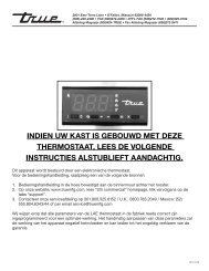
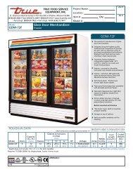
INSTALLATION OF CASTORS OR OPTIONAL LEGS<br />
Important Safeguard for installation of leg/castor (Images 1-5 demonstrate procedure)<br />
Securing Castors and Legs<br />
To obtain maximum strength and stability of the unit,<br />
it is important that you make sure each castor is secure.<br />
Optional legs are hand-tightened securely against the<br />
lower rail assembly see image 4-5. The bearing race on<br />
the castor or the top edge of the leg must make firm<br />
contact with the rail.<br />
Unit leveling<br />
Four leveling shims have been provided for leveling<br />
castored units positioned on uneven floors. Shims must<br />
be positioned between rail end and bearing race.<br />
A. Turn the bearing race counter-clockwise until the<br />
cabinet is level. Level front to back and side to side.<br />
(diagonally)<br />
1 2 3 4<br />
5<br />
B. Install the desired number of shims, making sure the<br />
slot of the shim is in contact with the threaded stem<br />
of the castor. (See image 2)<br />
C. If more than one shim is used, turn the slot at a 90°<br />
angle so they are not in line.<br />
D. Turn the bearing race clockwise to tighten and secure<br />
the castor by tightening the anchoring bolt with a<br />
3/4 inch open-end wrench or the tool provided.<br />
(See image 3)<br />
CAUTION<br />
To avoid damage to lower rail assembly, slowly raise unit to<br />
upright position.<br />
NOTE<br />
Open holes located on the cross members of the frame rail<br />
should be plugged before unit is in use.<br />
Use the tool provided to tighten<br />
the castor into place.<br />
6 6<br />
Leg<br />
Castor<br />
Lower Rail Assembly<br />
Rail End<br />
Thread leg into cabinet bottom<br />
frame rail.<br />
Snug Fit<br />
Here<br />
Bearing<br />
Race
<strong>True</strong> Food Service Equipment, Inc.<br />
INSTALLATION / OPERATION INSTRUCTIONS<br />
CONDUCTORS AND CIRCUITS<br />
Wire Gauge for 2% Voltage Drop in Supply Circuits<br />
115 Volt Distance In Feet To Center of Load<br />
Amps 20 30 40 50 60 70 80 90 100 120 140 160<br />
2 14 14 14 14 14 14 14 14 14 14 14 14<br />
3 14 14 14 14 14 14 14 14 14 14 14 12<br />
4 14 14 14 14 14 14 14 14 14 12 12 12<br />
5 14 14 14 14 14 14 14 12 12 12 10 10<br />
6 14 14 14 14 14 14 12 12 12 10 10 10<br />
7 14 14 14 14 14 12 12 12 10 10 10 8<br />
8 14 14 14 14 12 12 12 10 10 10 8 8<br />
9 14 14 14 12 12 12 10 10 10 8 8 8<br />
10 14 14 14 12 12 10 10 10 10 8 8 8<br />
12 14 14 12 12 10 10 10 8 8 8 8 6<br />
14 14 14 12 10 10 10 8 8 8 6 6 6<br />
16 14 12 12 10 10 8 8 8 8 6 6 6<br />
18 14 12 10 10 8 8 8 8 8 8 8 5<br />
20 14 12 10 10 8 8 8 6 6 6 5 5<br />
25 12 10 10 8 8 6 6 6 6 5 4 4<br />
30 12 10 8 8 6 6 6 6 5 4 4 3<br />
35 10 10 8 6 6 6 5 5 4 4 3 2<br />
40 10 8 8 6 6 5 5 4 4 3 2 2<br />
45 10 8 6 6 6 5 4 4 3 3 2 1<br />
50 10 8 6 6 5 4 4 3 3 2 1 1<br />
Wire Gauge for 2% Voltage Drop in Supply Circuits<br />
230 Volts Distance In Feet To Center of Load<br />
Amps 20 30 40 50 60 70 80 90 100 120 140 160<br />
5 14 14 14 14 14 14 14 14 14 14 14 14<br />
6 14 14 14 14 14 14 14 14 14 14 14 12<br />
7 14 14 14 14 14 14 14 14 14 14 12 12<br />
8 14 14 14 14 14 14 14 14 14 12 12 12<br />
9 14 14 14 14 14 14 14 14 12 12 12 10<br />
10 14 14 14 14 14 14 14 12 12 12 10 10<br />
12 14 14 14 14 14 14 12 12 12 10 10 10<br />
14 14 14 14 14 14 12 12 12 10 10 10 8<br />
16 14 14 14 14 12 12 12 10 10 10 8 8<br />
18 14 14 14 12 12 12 10 10 10 8 8 8<br />
20 14 14 14 12 10 10 10 10 10 8 8 8<br />
25 14 14 12 12 10 10 10 10 8 8 6 6<br />
30 14 12 12 10 10 10 8 8 8 6 6 6<br />
35 14 12 10 10 10 8 8 8 8 6 6 5<br />
40 14 12 10 10 8 8 8 6 6 6 5 5<br />
50 12 10 10 8 6 6 6 6 6 5 4 4<br />
60 12 10 8 6 6 6 6 6 5 4 4 3<br />
70 10 10 8 6 6 6 5 5 4 4 2 2<br />
80 10 8 8 6 6 5 5 4 4 3 2 2<br />
90 10 8 6 6 5 5 4 4 3 3 1 1<br />
100 10 8 6 6 5 4 4 3 3 2 1 1<br />
............ www.truemfg.com ............<br />
7 7
INSTALLATION / OPERATION INSTRUCTIONS<br />
ELECTRICAL INSTRUCTIONS<br />
A. Before your new unit is connected to a power supply,<br />
check the incoming voltage with a voltmeter. If<br />
anything less than 100% of the rated voltage for<br />
operation is noted, correct immediately.<br />
B. All units are equipped with a service cord, and must<br />
be powered at proper operating voltage at all times.<br />
Refer to cabinet data plate for this voltage.<br />
TRUE requires that a sole use circuit be dedicated for the<br />
unit. Failure to do so voids warranty.<br />
SEALING CABINET TO FLOOR<br />
Step 1 - Position Cabinet<br />
Allow one inch between the wall and rear of the<br />
<strong>refrigerator</strong> to assure proper ventilation. For <strong>freezer</strong>s<br />
3 inches between the wall and rear of the cabinet will<br />
assure proper ventilation.<br />
Step 2 - Level Cabinet<br />
Cabinet should be level, side to side and front to back.<br />
Place a carpenter’s level in the interior floor in four<br />
places:<br />
A. Position level in the inside floor of the unit near the<br />
<strong>door</strong>s. (Level should be parallel to cabinet front).<br />
Level cabinet.<br />
B. Position level at the inside rear of cabinet. (Again<br />
level should be placed parallel to cabinet back).<br />
C. Perform similar procedures to steps a & b by placing<br />
the level on inside floor (left and right sides - parallel<br />
to the depth of the cooler). Level cabinet.<br />
Step 3<br />
Draw an outline on the base on the floor.<br />
Step 4<br />
Raise and block the front side of the cabinet.<br />
Step 5<br />
Apply a bead of “NSF Approved Sealant”, (see list<br />
below), To floor on half inch inside the outline drawn.<br />
The bead must be heavy enough to seal the entire cabinet<br />
surface when it is down on the sealant.<br />
............ www.truemfg.com ............<br />
<strong>True</strong> Food Service Equipment, Inc.<br />
WARNING<br />
Compressor warranties are void if compressor burns out<br />
due to low voltage.<br />
WARNING<br />
Power supply cord ground should not be removed!<br />
NOTE<br />
To reference wiring diagram - Remove front louvered grill,<br />
wiring diagram is positioned on the inside cabinet wall.<br />
Step 6<br />
Raise and block the rear of the cabinet<br />
Step 7<br />
Apply sealant on floor as outline in Step 5. on other<br />
three sides.<br />
Step 8<br />
Examine to see that cabinet is sealed to floor around<br />
entire perimeter.<br />
NOTE<br />
Asphalt floors are very susceptible to chemical attack. A<br />
layer of tape on the floor prior to applyingthe sealant will<br />
protect the floor.<br />
NSF Approved Sealants:<br />
1. Minnesota Mining #ECU800 Caulk<br />
2. Minnesota Mining #ECU2185 Caulk<br />
3. Minnesota Mining #ECU1055 Bead<br />
4. Minnesota Mining #ECU1202 Bead<br />
5. Armstrong Cork - Rubber Caulk<br />
6. Products Research Co. #5000 Rubber Caulk<br />
7. G.E. Silicone Sealer<br />
8. Dow Corning Silicone Sealer<br />
8 8
<strong>True</strong> Food Service Equipment, Inc.<br />
STARTUP<br />
INSTALLATION / OPERATION INSTRUCTIONS<br />
A. The compressor is ready to operate. Plug in the<br />
cooler.<br />
B. Factory approximate <strong>refrigerator</strong> temperature of 35°F<br />
and approximate <strong>freezer</strong> temperature of -10˚F. Allow<br />
unit to function several hours, completely cooling<br />
cabinet before changing the control setting.<br />
C. Excessive tampering with the control could lead to<br />
service difficulties. Should it ever become necessary<br />
to replace temperature control, be sure it is ordered<br />
from your TRUE dealer or recommended service<br />
agent.<br />
D. Good air flow in your TRUE unit is critical. Be<br />
careful to load product so that it neither presses<br />
against the back wall, nor comes within four inches<br />
of the evaporator housing. Refrigerated air off the<br />
coil must circulate down the back wall.<br />
............ www.truemfg.com ............<br />
NOTE<br />
If the cooler is disconnected or shut off, wait five minutes<br />
before starting again.<br />
RECOMMENDATION<br />
Before loading product we recommend you run your TRUE<br />
unit empty for two to three days. This allows you to be sure<br />
electrical wiring and installation are correct and no shipping<br />
damage has occurred. Remember, our factory warranty<br />
does not cover product loss!<br />
REPLACEMENT PARTS<br />
TRUE maintains a record of the cabinet serial number<br />
for your cooler. If at any time during the life of your<br />
cooler, a part is needed, you may obtain this part by<br />
furnishing the model number and serial number to the<br />
company from whom you purchased the cooler. Call<br />
Toll-Free: (800)-424-TRUE (Direct to Parts Department).<br />
(800)-325-6152 (U.S.A. & Canada only) or call:<br />
(636)-240-2400.<br />
9 9
INSTALLATION / OPERATION INSTRUCTIONS<br />
............ www.truemfg.com ............<br />
<strong>True</strong> Food Service Equipment, Inc.<br />
SHELVING INSTALLATION / OPERATION &<br />
LIGHT SWITCH LOCATION<br />
WARNING<br />
Do not use pliers or any crimping tools when<br />
installing shelf clips. Altering shelf clips in any<br />
way can lead to shelving instability.<br />
For Proper Shelf Clip Installation Please<br />
Read The Following Instructions.<br />
Step 1<br />
Shelf clips are to be installed into the shelf<br />
standards next to the labels on the interior<br />
cabinet wall. This label can be seen in<br />
images 1-4. Install the top tab of the shelf<br />
clip into the proper hole. Push up on the<br />
bottom of the clip. (See image 1).<br />
SHELF & ORGANIZER INSTALLATION:<br />
Step 1<br />
A. Hook shelf clips onto shelf standards. (see illustration).<br />
B. Position all four shelf clips equal in distance from the<br />
floor for flat shelves.<br />
WIRE SHELVES<br />
Wire shelves are oriented so that cross support bars are facing down.<br />
NOTE<br />
T-Series models include an airflow guard on the rear of shelves to<br />
maintain an air space at the rear of the cabinet. (see illustration).<br />
Step 2<br />
Place shelves on shelf clips making sure all corners are seated<br />
properly.<br />
1<br />
(Installing top tab of shelf clip)<br />
Step 2<br />
Bottom tab of the shelf clip will fit tightly.<br />
You may need to squeeze or twist the<br />
bottom of the shelf clip to install. (See<br />
image 2 & 3).<br />
2<br />
(Installing bottom of the shelf clip)<br />
LIGHT SWITCH LOCATION:<br />
Light switch location depends upon the T-Series model. Most<br />
T-Series models will have the light switch located inside the unit on<br />
the right side of the ceiling. Some models have the switch located<br />
on the right side of the evaporator housing along the interior ceiling.<br />
10 10<br />
Shelf<br />
Shelf<br />
Clip<br />
T-Series<br />
& GDM-5<br />
Airflow<br />
Guard<br />
3<br />
You may need to squeeze or twist the bottom<br />
of the shelf clip to install)<br />
4<br />
(Shelf clip installation complete)<br />
Step 3<br />
After installation, the shelf clip will fit snug<br />
into the shelf standard. The shelf clip should<br />
not be loose or able to wiggle out of the<br />
shelf standard.<br />
Shelf Installation Tips<br />
1. Install all the shelf clips before installing<br />
the shelves.<br />
2. Start at the bottom in terms of shelf<br />
installation and work your way up.<br />
3. Always lay the back of each shelf down<br />
on the rear clips before the front.<br />
Pillaster<br />
Shelf
<strong>True</strong> Food Service Equipment, Inc.<br />
DANFOSS TEMPERATURE CONTROL (FREEZER<br />
SEQUENCE OF OPERATION)<br />
1. Cabinet is plugged in.<br />
a. Display will illuminate showing “deF”.<br />
b. Cabinet will start in a Defrost Cycle.<br />
2. During the initial Defrost Cycle, the evaporator fan(s) and the compressor will remain off for a minimum of 4<br />
minutes.<br />
a. After the Defrost Cycle there will be a 2 minute delay.<br />
b. After the 2 minute delay the compressor will start.<br />
c. The evaporator fans will remain off for an additional 3 minutes.<br />
d. The display will continue to show “deF” for an additional 30 minutes.<br />
3. The electronic control will cycle the compressor and the evaporator fan(s) on and off determined by the<br />
Set-Point and Differential temperatures (Set-Point is adjustable).<br />
a. The Set-Point is the preprogrammed temperature which shuts off the compressor and evaporator fan(s).<br />
b. The Differential is the preprogrammed temperature that is added to the Set-Point temperature that will start<br />
the compressor and evaporator fan(s).<br />
c. The Danfoss control is designed to read and display a cabinet temperature. This cabinet temperature may<br />
reflect the refrigeration cycle of the Set-Point and it’s Differential.<br />
Example: If the Set-Point is -6°F/1°C and the Differential is 6°F/4°C<br />
(Set-Point) -6°F + 6 (Differential) = 0°F<br />
Or<br />
(Set-Point) -21.4°C + 3.3 (Differential) = -18.1°C<br />
The compressor will cycle off -6°F/-21.4°C and back on at 0°F/-18.1°C<br />
4. The electronic control is preprogrammed to initiate defrost every 4 hours of compressor run time<br />
(non-adjustable).<br />
a. At this time the evaporator fans and the compressor will turn off.<br />
b. Once a preprogrammed temperature of the evaporator coil is reached, the Defrost Cycle will terminate and the<br />
2 minute delay will occur.<br />
c. After the 2 minute delay the compressor will restart.<br />
d. The evaporator fans will remain off for an additional 3 minutes.<br />
e. The display will continue to show “deF” for an additional 30 minutes.<br />
TRUE <strong>Manufacturing</strong> recommends that only the Set-Point may be adjusted due to certain conditions.<br />
............ www.truemfg.com ............<br />
11 11
............ www.truemfg.com ............<br />
<strong>True</strong> Food Service Equipment, Inc.<br />
DANFOSS TEMPERATURE CONTROL<br />
(REFRIGERATOR SEQUENCE OF OPERATION)<br />
1. Cabinet is plugged in.<br />
a. Display will illuminate showing “deF”.<br />
b. Cabinet will start in a Defrost Cycle.<br />
2. During the initial Defrost Cycle, the evaporator fan(s) will run but the compressor will remain off for a minimum<br />
of 4 minutes.<br />
a. After the Defrost Cycle there will be a 2 minute delay and the evaporator fan(s) will stop.<br />
b. After the 2 minute delay the compressor will start, and evaporator fan(s) will delay 60 seconds.<br />
c. The display will continue to show “deF” for an additional 30 minutes.<br />
3. The electronic control will cycle the compressor and the evaporator fan(s) on and off determined by the<br />
Set-Point and Differential temperatures (Set-Point is adjustable).<br />
a. The Set-Point is the preprogrammed temperature which shuts off the compressor and evaporator fan(s).<br />
b. The Differential is the preprogrammed temperature that is added to the Set-Point temperature that will start<br />
the compressor and evaporator fan(s).<br />
c. The Danfoss control is designed to read and display a cabinet temperature. This cabinet temperature may<br />
reflect the refrigeration cycle of the Set-Point and it’s Differential.<br />
Example: If the Set-Point is 34°F/1.1°C and the Differential is 6°F/3.3°C<br />
(Set-Point) 34°F + 6 (Differential) = 40°F<br />
Or<br />
(Set-Point) 1.1°C + 3.3 (Differential) = 4.4°C<br />
The compressor will cycle off 34°F/1.1°C and back on at 40°F/4.4°C<br />
4. The electronic control is preprogrammed to initiate defrost every 4 hours of compressor run time<br />
(non-adjustable).<br />
a. At this time the evaporator fans will continue to run but the compressor will turn off.<br />
b. Once a preprogrammed temperature of the evaporator coil is reached, the Defrost Cycle will terminate and the<br />
2 minute delay will start stopping the evaporator fan(s).<br />
c. After the 2 minute delay the compressor will restart, and evaporator fan(s) will delay 60 seconds.<br />
d. The display will continue to show “deF” for an additional 30 minutes.<br />
TRUE <strong>Manufacturing</strong> recommends that only the Set-Point may be adjusted due to certain conditions.<br />
12 12
<strong>True</strong> Food Service Equipment, Inc.<br />
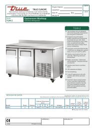
Danfoss Electronic Control (Power On)<br />
TURNING ON POWER<br />
A. Press both buttons to power on the temperature control.<br />
TURNING OFF POWER<br />
A. Press both buttons and hold for 6 seconds to power off<br />
the temperature control.<br />
............ www.truemfg.com ............<br />
Press both buttons to<br />
power on temp control<br />
Danfoss Electronic Control (Power Off)<br />
Press both buttons<br />
and hold for 6 seconds<br />
to power off temp<br />
control<br />
13 13
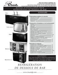
DEFROST<br />
A. Press bottom button and hold for 6 seconds to defrost.<br />
............ www.truemfg.com ............<br />
<strong>True</strong> Food Service Equipment, Inc.<br />
Danfoss Electronic Control (Defrost)<br />
Danfoss Electronic Control<br />
(Cut out Temperature)<br />
CUT OUT TEMPERATURE<br />
A. Press and release top or bottom button for 2 seconds<br />
to display cut out temperature.<br />
Press bottom button<br />
and hold for 6 seconds<br />
to start defrost<br />
Press and release top<br />
or bottom button for 2<br />
seconds to display cut<br />
out temperature<br />
CHANGE CUT OUT TEMPERATURE<br />
A. Raise or lower the set point use the top or bottom<br />
button to go up or down. Release the button and<br />
temperature will go back.<br />
NOTE - Cut in temperature is the set point plus the fix<br />
differential.<br />
14 14<br />
or
<strong>True</strong> Food Service Equipment, Inc.<br />
REQUIRED TOOLS:<br />
• Phillips Screwdriver<br />
• Stiff Bristle Brush<br />
• Adjustable Wrench<br />
• Air Tank or CO Tank • Vacuum Cleaner<br />
2<br />
Step 1<br />
Disconnect power to unit.<br />
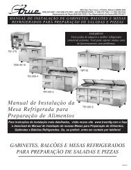
Step 2<br />
SLIDE DOOR MODELS: (See Image 1)<br />
Take off lower grill assembly by removing two (2) screws in<br />
lower corners. (older models may have snap lock tabs instead<br />
of screws).<br />
Loosen screws holding the top pivot pins. Swing grill up and<br />
remove frame hooks from pivot pins at top of louver.<br />
MAINTENANCE, CARE & CLEANING<br />
MAINTENANCE, CARE & CLEANING<br />
CLEANING THE CONDENSER COIL<br />
When using electrical appliances, basic safety precautions should be followed, including the following:<br />
SWING DOOR MODELS: (See Image 2)<br />
Take off lower grill assembly by opening the <strong>door</strong> and<br />
removing screws from the top of the louver grill. Some models<br />
have a <strong>door</strong> light switch. Please use caution when removing<br />
the grill on these models. Do not pinch wires. For reinstall,<br />
reattach the grill to the magnets on front of the cabinet and<br />
reinstall the screws on top of the grill.<br />
Step 3<br />
Remove bolts anchoring compressor assembly to frame rails<br />
and carefully slide out. (tube connections are flexible)<br />
Step 4<br />
Clean off accumulated dirt from the condenser coil and the<br />
fan with a stiff bristle brush.<br />
Step 5<br />
Lift cardboard cover above fan at plastic plugs and carefully<br />
clean condenser coil and fan blades.<br />
Step 6<br />
INDOOR LOCATION:<br />
After brushing condenser coil vacuum dirt from coil, and<br />
interior floor.<br />
OUTDOOR LOCATION:<br />
(GDM-33, GDM-47, and GDM-49 only) After brushing<br />
condenser coil blow CO 2 through condenser from fin side to<br />
fan. (See Image 4.)<br />
Step 7<br />
Replace cardboard cover. Carefully slide compressor assembly<br />
back into position and replace bolts.<br />
............ www.truemfg.com ............<br />
Step 8<br />
Reinstall louver assembly onto unit with appropriate fastener<br />
and clips. Tighten all screws.<br />
Step 9<br />
Connect unit to power and check to see if compressor is<br />
running.<br />
15 15<br />
1<br />
Slide Door Models<br />
Image 3.<br />
Image 4.<br />
2<br />
Swing Door Models<br />
P<br />
NEPCO/CENTRALAB<br />
1227-5<br />
REMOVE COVER MAKE POWER CONNECTION<br />
E. McCabe
............ www.truemfg.com ............<br />
<strong>True</strong> Food Service Equipment, Inc.<br />
Condensers accumulate dirt and require cleaning every 30 days. Dirty condensers result in compressor failure, product loss,<br />
and lost sales... which are not covered by warranty.<br />
If you keep the Condenser clean you will minimize your service expense and lower your electrical costs. The Condenser<br />
requires scheduled cleaning every thirty days or as needed.<br />
Air is pulled through the Condenser continuously, along with dust, lint, grease, etc.<br />
A dirty Condenser can result in NON-WARRANTEED part & Compressor Failures, Product Loss, and Lost Sales.<br />
Proper cleaning involves removing dust from the Condenser. By using a soft brush, or vacuuming the Condenser with a shop<br />
vac, or using CO2, nitrogen, or pressurized air.<br />
If you cannot remove the dirt adequately, please call your refrigeration service company.<br />
On most of the units the condenser is accessible in the rear of the unit. You must remove the cabinet grill to expose the<br />
Condenser.<br />
The Condenser looks like a group of vertical fins. You need to be able to see through the condenser for the unit to function at<br />
maximum capacity. Do not place filter material in front of condensing coil. This material blocks air-flow to the coil similar to<br />
having a dirty coil.<br />
THE CLEANING OF THE CONDENSER IS NOT<br />
COVERED BY THE WARRANTY!<br />
MAINTENANCE, CARE & CLEANING<br />
IMPORTANT WARRANTY INFORMATION<br />
HOW TO CLEAN THE CONDENSER:<br />
1. Disconnect the electrical power to the unit.<br />
2. Remove the louvered grill.<br />
3. Vacuum or brush the dirt, lint, or debris from the finned condenser coil.<br />
4. If you have a significant dirt build up you can blow out the condenser with compressed air.<br />
(CAUTION MUST BE USED to avoid eye injury. Eye protection is recommended.)<br />
5. When finished be sure to replace the louvered grill. The grill protects the condenser.<br />
6. Reconnect the electrical power to the unit.<br />
If you have any questions, please call TRUE <strong>Manufacturing</strong> at 636-240-2400 or 800-325-6152 and ask for the Service<br />
Department. Service Department Availability Monday-Friday 7:30 a.m. to 5:30p.m. and Saturday 8:00 a.m. to 12:00 a.m. CST.<br />
16 16
<strong>True</strong> Food Service Equipment, Inc.<br />
MAINTENANCE, CARE & CLEANING<br />
Stainless Steel Equipment Care and Cleaning<br />
CAUTION: Do not use any steel wool, abrasive or chlorine based products to clean stainless steel surfaces.<br />
• Stainless Steel Opponents<br />
There are three basic things which can break down your stainless steel’s passivity layer and allow corrosion to rear<br />
its ugly head.<br />
1) Scratches from wire brushes, scrapers, and steel pads are just a few examples of items that can be abrasive to<br />
stainless steel’s surface.<br />
2) Deposits left on your stainless steel can leave spots. You may have hard or soft water depending on what part of<br />
the country you live in. Hard water can leave spots. Hard water that is heated can leave deposits if left to sit too<br />
long. These deposits can cause the passive layer to break down and rust your stainless steel. All deposits left from<br />
food prep or service should be removed as soon as possible.<br />
3) Chlorides are present in table salt, food, and water. Household and industrial cleaners are the worst type of<br />
chlorides to use.<br />
• 8 steps that can help prevent rust on stainless steel:<br />
1. Using the correct cleaning tools<br />
Use non-abrasive tools when cleaning your stainless steel products. The stainless steel’s passive layer will not be<br />
harmed by soft cloths and plastic scouring pads. Step 2 tells you how to find the polishing marks.<br />
2. Cleaning along the polish lines<br />
Polishing lines or “grain” are visible on some stainless steels. Always scrub parallel to visible lines on some stainless<br />
steels. Use a plastic scouring pad or soft cloth when you cannot see the grain.<br />
3. Use alkaline, alkaline chlorinated or non-chloride containing cleaners<br />
While many traditional cleaners are loaded with chlorides, the industry is providing an ever increasing choice of<br />
non-chloride cleaners. If you are not sure of your cleaner’s chloride content contact your cleaner supplier. If they<br />
tell you that your present cleaner contains chlorides, ask if they have an alternative. Avoid cleaners containing<br />
quaternary salts as they can attack stainless steel, causing pitting and rusting.<br />
4. Water Treatment<br />
To reduce deposits, soften the hard water when possible. Installation of certain filters can remove corrosive and<br />
distasteful elements. Salts in a properly maintained water softener can be to your advantage. Contact a treatment<br />
specialist if you are not sure of the proper water treatment.<br />
5. Maintaining the cleanliness of your food equipment<br />
Use cleaners at recommended strength (alkaline, alkaline chlorinated or non-chloride). Avoid build-up of hard<br />
stains by cleaning frequently. When boiling water with your stainless steel equipment, the single most likely cause<br />
of damage is chlorides in the water. Heating any cleaners containing chlorides will have the same damaging effects.<br />
6. Rinse<br />
When using chlorinated cleaners you must rinse and wipe dry immediately. It is better to wipe standing cleaning<br />
agents and water as soon as possible. Allow the stainless steel equipment to air dry. Oxygen helps maintain the<br />
passivity film on stainless steel.<br />
7. Hydrochloric acid (muriatic acid) should never be used on stainless steel<br />
8. Regularly restore/passivate stainless steel<br />
............ www.truemfg.com ............<br />
17 17
WARNING<br />
Disconnect power to cabinet before replacing light bulbs.<br />
MAINTENANCE, CARE & CLEANING<br />
............ www.truemfg.com ............<br />
<strong>True</strong> Food Service Equipment, Inc.<br />
Stainless Steel Equipment Care and Cleaning<br />
Recommended cleaners for certain situations / environments of stainless steel<br />
A) Soap, ammonia and detergent medallion applied with a cloth or sponge can be used for routine<br />
cleaning.<br />
B) Arcal 20, Lac-O-Nu Ecoshine applied provides barrier film for fingerprints and smears.<br />
C) Cameo, Talc, Zud First Impression is applied by rubbing in the direction of the polished lines for<br />
stubborn stains and discoloring.<br />
D) Easy-off and De-Grease It oven aid are excellent for removals on all finishes for grease-fatty acids,<br />
blood and burnt-on foods.<br />
E) Any good commercial detergent can be applied with a sponge or cloth to remove grease and oil.<br />
F) Benefit, Super Sheen, Sheila Shine are good for restoration / passivation.<br />
NOTE<br />
The use of stainless steel cleaners or other such solvents is not<br />
recommended on plastic parts. Warm soap and water will suffice.<br />
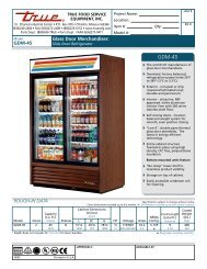
LIGHT BULB REPLACEMENT<br />
IDL (Integrated Door Lighting)<br />
1<br />
Interior Light<br />
2<br />
Interior Light<br />
INTERIOR LIGHTS:<br />
• Simply unscrew the light bulb(See Image 1 & 2).<br />
IDL (INTEGRATED DOOR LIGHTING):<br />
• Squeeze the plastic lampshield together and pull away<br />
from the <strong>door</strong> (See Image 3).<br />
• Push the bulb down while pulling the spring<br />
activated lampholder up. This will give you enough<br />
clearance to take the bulb out (See Image 4).<br />
3 4<br />
IDL (Integrated Door Lighting) IDL (Integrated Door Lighting)<br />
18 18
TRUE REFRIGERATION®<br />
MADE IN<br />
U.S.A.<br />
SINCE 1945<br />
WARRANTY INFORMATION (U.S.A & CANADA ONLY!)<br />
ONE YEAR PARTS & LABOR WARRANTY<br />
TRUE warrants to the original purchaser of every new TRUE refrigerated unit, the cabinet and all parts thereof, to be free from defects in material or workmanship,<br />
under normal and proper use and maintenance service as specified by TRUE and upon proper installation and start-up in accordance with the instruction packet supplied<br />
with each TRUE unit. TRUE’s obligation under this warranty is limited to a period of one (1) year from the date of original installation or 15 months after shipment date<br />
from TRUE, whichever occurs first.<br />
Any part covered under this warranty that are determined by TRUE to have been defective within one (1) year of original installation or fifteen (15) months after<br />
shipment date from manufacturer, whichever occurs first, is limited to the repair or replacement, including labor charges, of defective parts or assemblies. The labor<br />
warranty shall include standard straight time labor charges only and reasonable travel time, as determined by TRUE.<br />
ADDITIONAL FOUR YEAR COMPRESSOR WARRANTY<br />
In addition to the one (1) year warranty stated above, TRUE warrants its hermetically and semi-hermetically sealed compressor to be free from defects in both<br />
material and workmanship under normal and proper use and maintenance service for a period of four (4) additional years from the date of original installation but not to<br />
exceed five (5) years and three (3) months after shipment from the manufacturer.<br />
Compressors determined by TRUE to have been defective within this extended time period will, at TRUE’s option, be either repaired or replaced with a compressor<br />
or compressor parts of similar design and capacity.<br />
The four (4) year extended compressor warranty applies only to hermetically and semi-hermetically sealed parts of the compressor and does not apply to any other<br />
parts or components, including, but not limited to, cabinet, paint finish, temperature control, refrigerant, metering device, driers, motor starting equipment, fan assembly<br />
or any other electrical component, etcetera.<br />
404A/134A COMPRESSOR WARRANTY<br />
The four year compressor warranty detailed above will be voided if the following procedure is not carefully adhered to:<br />
1. This system contains R404A or R134A refrigerant and polyol ester lubricant. The polyol ester lubricant has rapid moisture absorbing qualities. If long exposure to<br />
the ambient conditions occur, the lubricant must be removed and replaced with new. For oil amounts and specifications please call TRUE technical service department<br />
(800-325-6152). Failure to comply with recommended lubricant specification will void the compressor warranty.<br />
2. Drier replacement is very important and must be changed when a system is opened for servicing. A drier using XH-7 desiccant or an exact replacement solid core<br />
drier must be used. The new drier must also be the same capacity as the drier being replaced.<br />
3. Micron level vacuums must be achieved to insure low moisture levels in the system. 500 microns or lower must be obtained.<br />
WARRANTY CLAIMS<br />
All claims for labor or parts must be made directly through TRUE. All claims should include: model number of the unit, the serial number of the cabinet, proof of<br />
purchase, date of installation, and all pertinent information supporting the existence of the alleged defect.<br />
In case of warranty compressor, the compressor model tag must be returned to TRUE along with above listed information.<br />
Any action or breach of these warranty provisions must be commenced within one (1) year after that cause of action has occurred.<br />
WHAT IS NOT COVERED BY THIS WARRANTY<br />
TRUE’s sole obligation under this warranty is limited to either repair or replacement of parts, subject to the additional limitations below. This warranty neither<br />
assumes nor authorizes any person to assume obligations other than those expressly covered by this warranty.<br />
NO CONSEQUENTIAL DAMAGES. TRUE IS NOT RESPONSIBLE FOR ECONOMIC LOSS; PROFIT LOSS; OR SPECIAL, INDIRECT, OR CONSEQUENTIAL<br />
DAMAGES, INCLUDING WITHOUT LIMITATION, LOSSES OR DAMAGES ARISING FROM FOOD OR PRODUCT SPOILAGE CLAIMS WHETHER OR NOT ON ACCOUNT<br />
OF REFRIGERATION FAILURE.<br />
WARRANTY IS NOT TRANSFERABLE. This warranty is not assignable and applies only in favor of the original purchaser/user to whom delivered. ANY SUCH<br />
ASSIGNMENT OR TRANSFER SHALL VOID THE WARRANTIES HEREIN MADE AND SHALL VOID ALL WARRANTIES, EXPRESS OR IMPLIED, INCLUDING ANY<br />
WARRANTY OF MERCHANTABILITY OR FITNESS FOR A PARTICULAR PURPOSE.<br />
IMPROPER USAGE. TRUE ASSUMES NO LIABILITY FOR PARTS OR LABOR COVERAGE FOR COMPONENT FAILURE OR OTHER DAMAGES RESULTING FROM<br />
IMPROPER USAGE OR INSTALLATION OR FAILURE TO CLEAN AND/OR MAINTAIN PRODUCT AS SET FORTH IN THE WARRANTY PACKET PROVIDED WITH THE<br />
UNIT.<br />
RESIDENTIAL APPLICATIONS: TRUE assumes no liability for parts or labor coverage for component failure or other damages resulting from installation in<br />
non-commercial or residential applications.<br />
ALTERATION, NEGLECT, ABUSE, MISUSE, ACCIDENT, DAMAGE DURING TRANSIT OR INSTALLATION, FIRE, FLOOD, ACTS OF GOD. TRUE is not responsible<br />
for the repair or replacement of any parts that TRUE determines have been subjected after the date of manufacture to alteration, neglect, abuse, misuse, accident,<br />
damage during transit or installation, fire, flood, or act of God.<br />
IMPROPER ELECTRICAL CONNECTIONS. TRUE IS NOT RESPONSIBLE FOR THE REPAIR OR REPLACEMENT OF FAILED OR DAMAGED COMPONENTS<br />
RESULTING FROM ELECTRICAL POWER FAILURE, THE USE OF EXTENSION CORDS, LOW VOLTAGE, OR VOLTAGE DROPS TO THE UNIT.<br />
NO IMPLIED WARRANTY OF MERCHANTABILITY OR FITNESS FOR A PARTICULAR PURPOSE: THERE ARE NO OTHER WARRANTIES, EXPRESSED, IMPLIED<br />
OR STATUTORY, EXCEPT THE ONE (1) YEAR PARTS & LABOR WARRANTY AND THE ADDITIONAL FOUR (4) YEAR COMPRESSOR WARRANTY AS DESCRIBED<br />
ABOVE. THESE WARRANTIES ARE EXCLUSIVE AND IN LIEU OF ALL OTHER WARRANTIES, INCLUDING IMPLIED WARRANTY AND MERCHANTABILITY OR FITNESS<br />
FOR A PARTICULAR PURPOSE. THERE ARE NO WARRANTIES WHICH EXTEND BEYOND THE DESCRIPTION ON THE FACE HEREOF.<br />
OUTSIDE U.S./Canada: This warranty does not apply to, and TRUE is not responsible for, any warranty claims made on products sold or used outside the United<br />
States or Canada.<br />
19 ............ www.truemfg.com ............<br />
19