Interplanetary Mission Design Handbook, Volume I, Part 2
Interplanetary Mission Design Handbook, Volume I, Part 2
Interplanetary Mission Design Handbook, Volume I, Part 2

You also want an ePaper? Increase the reach of your titles
YUMPU automatically turns print PDFs into web optimized ePapers that Google loves.
cos 8 -<br />
sin EL LIMIT + COS 0L<br />
(14)<br />
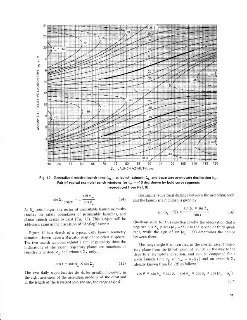
As 5,, gets longer, the sector of unavailable launch azimuths<br />
reaches the safety boundaries of permissible launches, and<br />
planar launch ceases to exist (Fig . 13) .' This subject will be<br />
addressed again in the discussion of "dogleg" ascents .<br />
Figure 14 is a sketch of a typical daily launch geometry<br />
situation, shown upon a Mercator map of the celestial sphere .<br />
The two launch windows exhibit a similar geometry since the<br />
inclinations of the ascent trajectory planes are functions of<br />
launch site latitude OL and azimuth E L only :<br />
cos i = cos 01, X sin E L (15)<br />
The two daily opportunities do differ greatly, however, in<br />
the right ascension of the ascending mode S2 of the orbit and<br />
in the length of the-traversed in-plane arc, the range angle 0 .<br />
The angular equatorial distance between the ascending node<br />
and the launch site meridian is given by<br />
sin X sin EL<br />
sin (a, -- Q) = L<br />
sin i<br />
(16)<br />
Quadrant rules for this equation involve the observation that a<br />
negative cos E L places (UL - 2) into the second or third quadrant,<br />
while the sign of sin (a 1 - 2) determines the choice<br />
between them .<br />
The range angle 0 is measured in the inertial ascent trajectory<br />
plane from the lift-off point at launch all the way to the<br />
departure asymptote direction, and can be computed for a<br />
given launch time t I or a te, - a L (tL ) and an azimuth E L<br />
already known from Eq . (9) as follows :<br />
cos 8 = sin 5 X sin OL +cos 8 - X cos 0I X cos (a,, - al )<br />
(17)