Interplanetary Mission Design Handbook, Volume I, Part 2
Interplanetary Mission Design Handbook, Volume I, Part 2
Interplanetary Mission Design Handbook, Volume I, Part 2

Create successful ePaper yourself
Turn your PDF publications into a flip-book with our unique Google optimized e-Paper software.
Another pair of significant variables on which to base<br />
arrival date selection are ZAPS and ZAPE-the angles between<br />
V-infinity and the planet-to-Sun and -Earth vectors, respectively<br />
. These two angles represent the cone angle (CA) of the<br />
planet during the far-encounter phase for a Sun- or an Earthoriented<br />
spacecraft, in that order . ZAPS also determines the<br />
phase angle, 4)S , of the planet's solar illumination, as seen by<br />
the spacecraft on its far-encounter approach leg to the planet :<br />
4)S = 180 -ZAPS (35)<br />
Both the cone angle and the phase angle have already been<br />
defined and discussed in the Earth departure section above .<br />
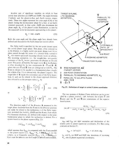
The flyby itself is specified by the aim point chosen upon<br />
the arrival planet target plane . This plane, often referred to<br />
as the B-plane, is a highly useful aim point design tool . It is a<br />
plane passed through the center of a celestial body normal to<br />
V_ , the relative spacecraft incoming velocity vector at infinity .<br />
The incoming asymptote, i .e ., the straight-line, zero-gravity<br />
extension of the V - -vector, penetrates the B-plane at the aim<br />
point . This point, defined by the target vector B in_ the B-plane,<br />
is often described by its two components B - T and B - R,<br />
where the axes T and R form an orthogonal set with Vim . The<br />
T-axis is chosen to be parallel to a fundamental plane, usually<br />
the ecliptic (Fig . 21) or alternatively, the planet's equator . The<br />
magnitude of B equals the semi-minor axis of the flyby hyperbola,<br />
b, and can be related to the closest approach distance,<br />
also referred to as the periapse radius, rn , by<br />
or<br />
r /2<br />
V2 r 2<br />
µ<br />
I B I= 2 1+<br />
, km (36)<br />
V~ µ pp)<br />
- 1<br />
P<br />
µ 2 1/2<br />
Vz<br />
1 Vz ) + I B 2<br />
+ (<br />
km (37)<br />
The direction angle 0 of the B-vector, B, measured in the<br />
target plane clockwise from the T-axis to the B-vector position<br />
can easily be related to the inclination, i, of the flyby trajectory,<br />
provided that both & (DAP) and the T-axis, from which<br />
B is measured clockwise, are defined with respect to the same<br />
fundamental plane to which the inclination is desired . For a<br />
system based on the planet equator (Fig . 22) :<br />
cos iPEQ = cos BPEQ X cos S °°<br />
PEQ<br />
(38)<br />
which assumes that 0PFQ is computed with the T-axis parallel<br />
to the planet equator (i .e ., TPEQ = V X POLEPEQ ), not the<br />
ecliptic, as is frequently assumed (TECL = VV X POLEECL) .<br />
Care must be taken to use the 0 angle as defined and intended .<br />
The two systems of B-plane T-axis definition can be reconciled<br />
by a planar rotation, -O0, between the ecliptic T- and<br />
R-axes and the T'- and axis orientations of the equator<br />
based system<br />
where<br />
sin (a_ - aEP)<br />
tan AB = cos 5 - X tan SEP - sin S_ X cos (a_ - aEP )<br />
(39)<br />
aEP and SEP are right ascension and declination of the<br />
ecliptic pole in planet equatorial coordinates . For Mars using<br />
constants in Section V :<br />
aEP = 267 .6227, SEP = 63 .2838, deg<br />
a_ and 5_ are RAP and DAP, the directions of incoming<br />
V_, also in planet equatorial coordinates .