Banner SI-QM100 Series Locking Style Machine Safety Switches
Banner SI-QM100 Series Locking Style Machine Safety Switches
Banner SI-QM100 Series Locking Style Machine Safety Switches

Create successful ePaper yourself
Turn your PDF publications into a flip-book with our unique Google optimized e-Paper software.
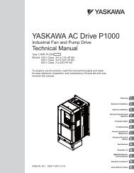
<strong>Safety</strong> Switch #1 <strong>Safety</strong> Switch #2<br />
32<br />
31<br />
22<br />
21<br />
Figure . Connect two redundant safety<br />
switches per interlock guard to an<br />
appropriate -channel input safety<br />
module.<br />
Solenoid<br />
Voltage<br />
Input<br />
Channel<br />
#1<br />
2-channel <strong>Safety</strong> Module<br />
E1<br />
E2<br />
13<br />
Input<br />
Channel<br />
#2<br />
(2-channel E-stop Module<br />
2-channel Gate Monitor Module, etc.)<br />
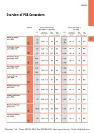
43 44<br />
14 21 22 31<br />
Figure . Switch electrical connections<br />
— models <strong>SI</strong>-<strong>QM100</strong>..G<br />
32<br />
31<br />
22<br />
21<br />
32<br />
Single gate<br />
or guard<br />
NOTE: Refer to the installation instructions<br />
provided with the safety module for<br />
information regarding the interface of<br />
the safety module to the machine stop<br />
control elements.<br />
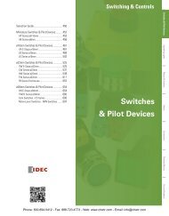
Solenoid<br />
Voltage<br />
E1<br />
E2<br />
11<br />
43 44<br />
12 21 22 31<br />
Figure . Switch electrical connections<br />
— models <strong>SI</strong>-<strong>QM100</strong>..DSH<br />
32<br />
<strong>Machine</strong> <strong>Safety</strong> Switch – <strong>SI</strong>-<strong>QM100</strong> <strong>Series</strong>, <strong>Locking</strong> <strong>Style</strong><br />
Two functions of the safety module or safety interface are:<br />
1. to provide a means of monitoring the contacts of both safety switches for contact failure,<br />
and to prevent the machine from restarting if either switch fails; and<br />
2. to provide a reset routine after closing the guard and returning the safety contacts to their<br />
closed position. This prevents the controlled machinery from restarting by simply reinserting<br />
the safety switch actuators. This necessary reset function is required by AN<strong>SI</strong> B11 and<br />
NFPA 79 machine safety standards.<br />
Use only positively driven, normally closed safety contacts from each switch for connection<br />
to the safety module. The normally open contacts may be used for control functions that are<br />
not safety-related. A typical use is to communicate with a process controller. Refer to the<br />
installation instructions provided with the safety modules for more information regarding the<br />
interface of the safety module to the machine stop control elements.<br />
Periodic Checks<br />
<strong>Safety</strong> switches should be checked at each shift change or machine setup by a designated<br />
person (see below) for:<br />
1. Breakage of the switch body or actuator,<br />
2. Good alignment and full engagement of the actuator with the receptor,<br />
3. Confirmation that the safety switch is not being used as an end stop,<br />
4. Loosening of the switch or actuator mounting hardware, and<br />
5. Verification that it is not possible to reach any hazard point through an opened guard (or<br />
any opening) before hazardous machine motion has completely stopped.<br />
In addition, a qualified person should check for the following on a periodic schedule,<br />
determined by the user, based upon the severity of the operating environment and the<br />
frequency of switch actuations:<br />
1. Check the wiring chamber for signs of contamination.<br />
2. Check the contacts for signs of deterioration or damage.<br />
3. Inspect the electrical wiring for continuity and damage.<br />
4. Verify that wiring conforms to the instructions on pages 4 and 5 of this data sheet.<br />
A designated person is identified in writing by the employer as being appropriately trained to<br />
perform a specified checkout procedure. A qualified person possesses a recognized degree or<br />
certificate or has extensive knowledge, training, and experience to be able to solve problems<br />
relating to the safety switch installation.<br />
Clearwater Tech - Phone: 800.894.0412 - Fax: 208.368.0415 - Web: www.clrwtr.com - Email: info@clrwtr.com