LTI 20.20 UltraLyte 1000 Operations Manual - Tele-Traffic
LTI 20.20 UltraLyte 1000 Operations Manual - Tele-Traffic
LTI 20.20 UltraLyte 1000 Operations Manual - Tele-Traffic

You also want an ePaper? Increase the reach of your titles
YUMPU automatically turns print PDFs into web optimized ePapers that Google loves.
RFI Considerations<br />
The <strong>UltraLyte</strong> <strong>1000</strong> does not display a specific error message indicating the presence of radio frequency interference (RFI). The<br />
instrument’s electronics have been designed for optimum RFI immunity.<br />
If RFI is present, the instrument displays an error code. The exact code depends on the level and nature of the RFI.<br />
Section 2 – Speed Measurements<br />
When you power ON the <strong>UltraLyte</strong> <strong>1000</strong>, the screen display should look similar to Figure 15.<br />
Taking a Sample Measurement<br />
Figure 15: Initial Speed Measurement Screen<br />
Refer to the instructions below to take a sample speed measurement.<br />
1. Ensure that the <strong>UltraLyte</strong> <strong>1000</strong> is powered ON and that the Speed Mode is active.<br />
2. Use the sighting scope to aim the instrument to a convenient target – an interior wall will do.<br />
3. Fire the laser:<br />
• Press and hold the TRIGGER. The laser will fire after a short delay (about one-half of a second).<br />
-or-<br />
• Press the TRIGGER twice. The 1st press turns on the in-scope red aiming dot. The 2nd press takes the measurement.<br />
4. Continue to press the TRIGGER and keep the instrument sighted on the target:<br />
• A low-pitched growl means that the instrument is attempting to lock onto the target.<br />
• A low-pitched beep means that a measurement error occurred. An error code will be displayed.<br />
• A high-pitched beep means that a speed was captured. The measured speed will be displayed on the LCD screen<br />
and will be projected on the scope, just below the aiming dot.<br />
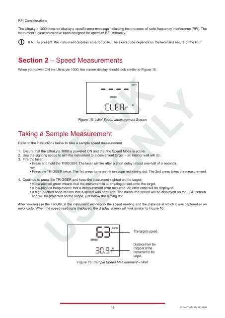
After you release the TRIGGER the instrument will display the speed reading and the distance at which it was captured or an<br />
error code. When the speed reading is displayed, the display screen will look similar to Figure 16.<br />
Figure 16: Sample Speed Measurement – Wall<br />
12<br />
© <strong>Tele</strong>-<strong>Traffic</strong> UK Ltd 2006