LTI 20.20 UltraLyte 1000 Operations Manual - Tele-Traffic
LTI 20.20 UltraLyte 1000 Operations Manual - Tele-Traffic
LTI 20.20 UltraLyte 1000 Operations Manual - Tele-Traffic

You also want an ePaper? Increase the reach of your titles
YUMPU automatically turns print PDFs into web optimized ePapers that Google loves.
Table 7 shows acceptable parameters for minimizing the cosine effect. The chart indicates the percentage of true speed<br />
measured, given the distance from the roadway and the distance from the target vehicle. To find a target’s measured speed,<br />
multiply the true speed by the number in the chart<br />
Distance off the<br />
Roadway<br />
(meters)<br />
Table 7. Percentage of True Speed Measured<br />
The diagonal created by the boldface numbers indicates the boundary between acceptable and unacceptable parameters.<br />
• Numbers above the diagonal are acceptable margins of error.<br />
• Numbers below the diagonal are unacceptable margins of error.<br />
Remember that the cosine effect is always in the motorist’s favour.<br />
Measuring a Moving Vehicle<br />
Range to Target Vehicle<br />
30 m 100 m 150 m 300 m 600 m<br />
fraction of true speeed that will be measured<br />
3 .9950 .9995 .9998 .9999 1.0000<br />
10 .9682 .9950 .9987 .9997 .9999<br />
15 .8660 .9886 .9950 .9987 .9997<br />
30 .0000 .9539 .9789 .9950 .9987<br />
60 .0000 .7999 .9165 .9798 .9950<br />
As a general rule, do not exceed 1 meter off the road for every 10 meters shooting down range to the targets. If target<br />
vehicles will be 150 meters down the road, set up no more that 15 meters off the road.<br />
Refer to the instructions below to use the <strong>UltraLyte</strong> <strong>1000</strong> to measure the speed of a moving vehicle.<br />
1. Ensure that the <strong>UltraLyte</strong> <strong>1000</strong> is powered ON and that the Speed Mode is active.<br />
2. Use the sighting scope to aim the instrument at the target’s vehicle’s license plate area and press the TRIGGER.<br />
3. Continue to press the TRIGGER and keep the instrument sighted on the target.<br />
• A low-pitched growl means that the instrument is attempting to lock onto the target<br />
• A low-pitched beep means that a measurement error occurred. An error code will be displayed.<br />
• A high-pitched beep means that a speed was captured. The measured speed will be displayed on the LCD screen and will<br />
be projected on the scope, just below the aiming dot.<br />
While the instrument is attempting to lock onto the target , as long as the TRIGGER is kept pressed, it will retry the speed<br />
measurement.<br />
• Depending upon it’s configuration, the instrument will try to 10 times or more. Information is accumulated until it gets a<br />
good measurement or generates an error code.<br />
• Consequently, it is very important that the aiming point on the target remain constant for the entire measurement time. If<br />
you move the instrument off the aiming point, it will generate an error code instead of capturing a speed reading.<br />
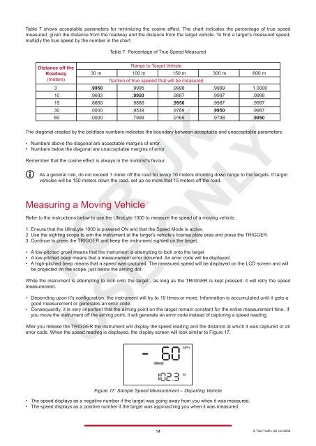
After you release the TRIGGER the instrument will display the speed reading and the distance at which it was captured or an<br />
error code. When the speed reading is displayed, the display screen will look similar to Figure 17.<br />
Figure 17: Sample Speed Measurement – Departing Vehicle<br />
• The speed displays as a negative number if the target was going away from you when it was measured.<br />
• The speed displays as a positive number if the target was approaching you when it was measured.<br />
14<br />
© <strong>Tele</strong>-<strong>Traffic</strong> UK Ltd 2006