SAW / STW Oscillators - TriQuint
SAW / STW Oscillators - TriQuint
SAW / STW Oscillators - TriQuint

You also want an ePaper? Increase the reach of your titles
YUMPU automatically turns print PDFs into web optimized ePapers that Google loves.
©9-12 <strong>TriQuint</strong> Semiconductor, Inc.<br />
Connecting the Digital World<br />
to the Global Network ®<br />
2012<br />
<strong>SAW</strong> / <strong>STW</strong> <strong>Oscillators</strong><br />
When nothing but the best<br />
phase noise performance<br />
will do for your application,<br />
be sure to design in <strong>TriQuint</strong><br />
frequency control products.
Oscillator Technology<br />
Enabling Technology - Why Choose <strong>TriQuint</strong> Frequency Control Products?<br />
All <strong>TriQuint</strong> oscillator products derive their frequency sources from a<br />
long history of innovation in technology for resonators. The resonator<br />
expertise of <strong>TriQuint</strong> has been developed over many years of iterations<br />
and fine tuning on models to produce high-performance resonators<br />
to meet the stringent demands of many applications. The resonators<br />
that <strong>TriQuint</strong> offers come in two types of designs that bring various<br />
features for your frequency control needs compared to traditional<br />
resonator technology.<br />
• <strong>SAW</strong> (Surface Acoustic Wave) resonators<br />
- More temperature stable than traditional resonators<br />
- High end g-sensitivity capability<br />
• <strong>STW</strong> (Surface Transverse Wave) resonators<br />
- Best available g-sensitivity with moderate temperature shift<br />
- Enables ultra low noise high-performance oscillators<br />
(best in class)<br />
<strong>TriQuint</strong> oscillators offer performance advantages in several areas:<br />
• High frequency fundamentals – When choosing a <strong>TriQuint</strong> oscillator,<br />
the system designer has an opportunity to simplify system design<br />
to minimize multiplication circuitry, associated gain and filtering<br />
stages typical in many system architectures. As a result of lower<br />
multiplication factors, systems will benefit from:<br />
- Improved noise floors<br />
- Better power consumption<br />
- Lower system cost<br />
- Improved phase noise curves<br />
- Smaller size<br />
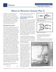
Quartz<br />
BAW<br />
Q <strong>SAW</strong><br />
Resonator Comparison<br />
<strong>STW</strong><br />
Ceramic Resonators<br />
Frequency<br />
LC<br />
Dielectric Resonators<br />
• Superior noise floor – The superior noise floor is obtained by using<br />
<strong>TriQuint</strong> high-performance resonators that leverage the surface<br />
wave advantages over traditional oscillator technology. Higher<br />
frequency oscillators have better noise floors than the traditional<br />
multiplied up lower frequency oscillators. This is due to the lack of<br />
phase noise degradation from multiplication, lack of conversion<br />
loss that must be made up with more gain and associated noise<br />
figure, as well a high power handling that allows for a better carrier<br />
to noise ratio.<br />
• Modular standard product platforms – <strong>TriQuint</strong> has multiple<br />
product families that have the ability to scale to different frequencies<br />
with very minimal development effort. In addition, since <strong>TriQuint</strong>’s<br />
standard loop oscillators are based on modular circuit functions, the<br />
standard products can support various performance enhancements<br />
in the areas of phase noise, noise floor, g-sensitivity, output power<br />
and signal type (ECL / sine wave). The result is flexibility to support<br />
customer needs in a standard product format.<br />
• Exceptional g-sensitivity is inherent in the resonator technology used.<br />
Connecting the Digital World to the Global Network ®<br />
| www.triquint.com | © 9-12 <strong>TriQuint</strong> Semiconductor, Inc. | p.2
The Enabling Technology of <strong>TriQuint</strong> <strong>Oscillators</strong><br />
<strong>TriQuint</strong>’s mature <strong>SAW</strong> / <strong>STW</strong> technology has allowed<br />
highly desirable oscillator performance to become readily<br />
available. Key advantages of <strong>TriQuint</strong> oscillators are:<br />
• Higher frequency operation (over 2 GHz possible)<br />
• Lower residual noise resonators allow for improved<br />
oscillator phase noise<br />
• Improved power handling capability allows for<br />
improved noise floors and higher RF output powers<br />
• Exceptional g-sensitivity performance results in<br />
oscillator relatively immune to microphonics<br />
<strong>TriQuint</strong>’s <strong>STW</strong> technology is mature, production ready and<br />
is a preferred choice on multiple major military programs.<br />
Vibration Sensitivity<br />
Equation 1 provides a means of determining the<br />
vibration sensitivity of an oscillator by measuring the<br />
ratio of the power in the sidebands to the power in the<br />
carrier when the oscillator is subjected to a sinusoidal<br />
vibration, (1) where f v is the vibration frequency, f 0 is<br />
the carrier frequency, a i is the vibration level in g’s,<br />
and is the single sideband-to-carrier power ratio.<br />
For random vibration, Equation 1 becomes Equation<br />
2 where G is the acceleration spectral density<br />
level in g 2 /Hz. The vibrational environment of the<br />
oscillator is usually specified in each of three mutually<br />
perpendicular axes. Vibration profiles typical of most<br />
military environments are specified in MIL-STD-883<br />
Method 2026.<br />
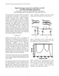
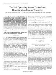
Graph 1 shows data measured in a direction<br />
perpendicular to the plane of propagation for <strong>STW</strong><br />
oscillators. As can be seen, extremely low values<br />
of g-sensitivity can be achieved with a trade-off<br />
in production yield and cost. <strong>TriQuint</strong> routinely<br />
manufactures oscillators as low as 5x10 -10/g . Through<br />
continuing production and development efforts,<br />
<strong>TriQuint</strong> intends to further push the state-of-the-art for<br />
this important parameter.<br />
Number of <strong>Oscillators</strong><br />
Image Courtesy of Lockheed Martin<br />
Equation 1<br />
g-Sensitivity Performance<br />
Equation 2<br />
Graph 1. Distribution of Performance g-Sensitivity of <strong>STW</strong> <strong>Oscillators</strong><br />
Connecting the Digital World to the Global Network ®<br />
| www.triquint.com | © 9-12 <strong>TriQuint</strong> Semiconductor, Inc. | p.3
2X .150<br />
4X .1025<br />
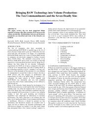
Standard Military Fixed Frequency <strong>Oscillators</strong><br />
<strong>TriQuint</strong>’s family of hybrid Fixed Frequency <strong>Oscillators</strong> (FFOs) is designed to<br />
achieve high performance at lower cost. Offered in operating frequencies<br />
from below 300 to above 1000 MHz, standard <strong>SAW</strong> FFOs are designed for<br />
military and space applications. Standard <strong>STW</strong> FFOs are available from<br />
500 to 1600 MHz and up.<br />
Advantages:<br />
• Quartz frequency stability<br />
• Excellent spectral purity and phase noise performance guaranteed<br />
• Low vibration sensitivity versions available<br />
• High endurance<br />
• Rugged, hermetic metal package<br />
• Off-the-shelf availability<br />
Standard Military FFO Phase Noise Performance at 750 MHz<br />
4X Ø.018<br />
±.002<br />
.498<br />
±.020<br />
.870 ±.020<br />
.600<br />
.210<br />
MAX.<br />
.300<br />
4-Pin Version of 14-Pin DIP<br />
Package Style H<br />
.180<br />
MIN.<br />
.530<br />
MAX.<br />
8X Ø.018<br />
4X .090<br />
MIN.<br />
.210<br />
MAX.<br />
.150<br />
.650 .350<br />
1.0” Flatpack<br />
Package PIN 710343<br />
Partial Freqeuncy Lisiting – <strong>SAW</strong><br />
Center Frequency<br />
(MHz)<br />
Connecting the Digital World to the Global Network ®<br />
| www.triquint.com | © 9-12 <strong>TriQuint</strong> Semiconductor, Inc. | p.4<br />
Package<br />
300 4 / 14 PIN DIP<br />
400 4 / 14 PIN DIP<br />
540 4 / 14 PIN DIP<br />
650 4 / 14 PIN DIP<br />
750 4 / 14 PIN DIP<br />
800 0.5”x1.0” Flatpack<br />
Partial Freqeuncy Lisiting – <strong>STW</strong><br />
Center Frequency<br />
(MHz)<br />
1.015<br />
.210<br />
MAX. MAX.<br />
.210<br />
.245<br />
.245<br />
1.500<br />
±.020<br />
1.300<br />
.900<br />
2X .150<br />
.800 1.000<br />
4X ±.020 .1025<br />
4X Ø.018<br />
±.002<br />
1.085<br />
.498 MAX.<br />
±.020<br />
Package<br />
500 4 / 14 PIN DIP<br />
650 0.5”x1.0” Flatpack<br />
720 MAX.<br />
*<br />
750 1.515 .180<br />
8X Ø.018<br />
MAX. MIN.<br />
* .183<br />
MAX.<br />
960 .153 4 / 14 PIN DIP<br />
.015<br />
±.003<br />
1000 4 / 14 PIN DIP<br />
1030 4 / 14 PIN DIP<br />
.870 ±.020<br />
.600 1090 4 / 14 PIN DIP<br />
1160 4 / 14 PIN DIP<br />
1200 .300<br />
*<br />
1280 *<br />
.50<br />
1300 MAX.<br />
*<br />
* Existing resonator frequency.<br />
.100 + .005<br />
TYP.<br />
.072<br />
±.008<br />
.150<br />
.650<br />
1.500<br />
±.020<br />
1.300<br />
.900<br />
.350<br />
.010<br />
±.002<br />
.210<br />
MAX.<br />
.800<br />
.245<br />
.245<br />
1.000<br />
±.020
Standard Military FFO Specifications<br />
Parameters Specifications<br />
Center Frequency<br />
RF Output Power<br />
at +25°C (65 mA max.)<br />
at +25°C (65 mA max.)<br />
280 -<br />
500 MHz<br />
500 -<br />
750 MHz<br />
+10 dBm Nominal<br />
+3 dBm Nominal<br />
750 -<br />
1000 MHz<br />
1000 -<br />
1400 MHz<br />
+10 dBm Nominal<br />
Variation of RF Output Power w/Temperature +8 to +13 dBm or 0 to +5 dBm +8 to +13 dBm Only<br />
Frequency Set Accuracy<br />
(+25°C)<br />
Frequency vs. Temperature<br />
Stability -55° to +85°C<br />
Frequency Pulling<br />
Load VSWR ≤ 1.5:1 at All Angles<br />
Spurious Output Attenuation<br />
Harmonic Spurious<br />
at 2 f 0<br />
at ≥ 3 f 0<br />
Non-Harmonic Spurious<br />
Exclusive of Supply Ripple<br />
Maximum SSB Phase Noise Level<br />
at 10 Hz<br />
at 100 Hz<br />
at 1 kHz<br />
at 10 kHz<br />
at 100 kHz<br />
at 1 MHz<br />
g-Sensitivity (f V < 2 KHz)<br />
<strong>SAW</strong> FFO<br />
<strong>STW</strong> FFO<br />
Power Supply<br />
RF = +12 to +14 dBm<br />
RF = +3 dBm<br />
dBc / Hz<br />
-40<br />
-70<br />
-95<br />
-125<br />
-150<br />
-160<br />
dBc / Hz<br />
-40<br />
-70<br />
-95<br />
-125<br />
-150<br />
-160<br />
± 50 ppm Standard<br />
≤ 250 ppm (<strong>SAW</strong>) ≤ 420 ppm (<strong>STW</strong>)<br />
≤ 30 ppm<br />
-15 dBc max.<br />
-30 dBc max.<br />
-60 dBc max.<br />
dBc / Hz<br />
-35<br />
-65<br />
-90<br />
-115<br />
-140<br />
-160<br />
dBc / Hz<br />
-30<br />
-60<br />
-85<br />
-110<br />
-140<br />
-160<br />
2 x 10 -8 /g to 1 x 10 -8 /g, Depending on Frequency<br />
1 x 10 -9 /g to 5 x 10 -10 /g, Depending on Frequency<br />
Operating Temperature Range -55° to +85°C<br />
Variations on performance are available upon request. Contact <strong>TriQuint</strong> with your application.<br />
Absolute Maximum Ratings<br />
DC Supply, Vcc<br />
RF = +12 to +14 dBm 0 to +13 VDC<br />
RF = 3 dBm 0 to +17 VDC<br />
Load VSWR Infinity<br />
Ambient Temperature<br />
Voltage<br />
+12 VDC ± 5%<br />
+12 or +15 VDC ± 5% (specify)<br />
Current<br />
65 mA max.<br />
25 mA max.<br />
Powered -55° to +95°C<br />
Storage -55° to +105°C<br />
Connecting the Digital World to the Global Network ®<br />
| www.triquint.com | © 9-12 <strong>TriQuint</strong> Semiconductor, Inc. | p.5<br />
1400 -<br />
1800 MHz<br />
dBc / Hz<br />
-25<br />
-55<br />
-80<br />
-105<br />
-135<br />
-155
8X Ø.018<br />
.150<br />
.650<br />
8X 1.500 Ø.018<br />
±.020<br />
1.300<br />
.900<br />
.150<br />
.350.650<br />
Standard Military Voltage Controlled <strong>Oscillators</strong><br />
<strong>TriQuint</strong>’s family of hybrid Voltage Controlled <strong>Oscillators</strong> (VCO) is designed<br />
for high performance at lower cost. Offered in operating frequencies from<br />
300 MHz to 2 GHz, these standard <strong>SAW</strong> VCOs are designed for military<br />
and space applications. Standard <strong>STW</strong> VCOs are available from 500 to<br />
1600 MHz and up. Sine wave and ECL outputs are available.<br />
Advantages:<br />
• Quartz frequency stability<br />
• Excellent spectral purity and phase noise performance guaranteed<br />
over the voltage tuning range<br />
• Excellent tuning linearity<br />
• Onboard voltage regulation<br />
• Low vibration sensitivity versions available<br />
• High endurance<br />
• Rugged, hermetic metal package<br />
Standard Military VCO Phase Noise Performance at 500 MHz<br />
1.500<br />
±.020<br />
1.300<br />
.900<br />
.210<br />
MAX.<br />
.800<br />
.350<br />
.150<br />
.650<br />
.245<br />
.245<br />
1.500<br />
±.020<br />
1.300<br />
.900<br />
1.000<br />
±.020<br />
.350<br />
.210<br />
MAX.<br />
.800<br />
.245<br />
.245<br />
.210<br />
MAX.<br />
1.000<br />
±.020<br />
.800<br />
.245<br />
.245<br />
1.085<br />
MAX.<br />
1.000<br />
±.020<br />
1.5” DIP<br />
Package Style 710232<br />
1.085<br />
MAX.<br />
1.515<br />
MAX.<br />
.015<br />
±.003<br />
1.085<br />
MAX.<br />
1.515<br />
MAX.<br />
.015<br />
±.003<br />
.100 + .005<br />
.1531.515<br />
TYP. MAX.<br />
.015<br />
±.003<br />
.50<br />
MAX.<br />
.100 + .005<br />
.153<br />
TYP.<br />
.50<br />
MAX.<br />
.183<br />
MAX.<br />
.072<br />
±.008<br />
.153<br />
TYP.<br />
.50<br />
MAX.<br />
.100 + .005 1.5” DIP<br />
Package Style 710320<br />
Partial Freqeuncy Lisiting – <strong>SAW</strong><br />
Center<br />
Frequency<br />
(MHz)<br />
Nominal Tuning<br />
Bandwidth<br />
(ppm)<br />
Connecting the Digital World to the Global Network ®<br />
| www.triquint.com | © 9-12 <strong>TriQuint</strong> Semiconductor, Inc. | p.6<br />
.183<br />
MAX.<br />
.072<br />
±.008<br />
.010<br />
±.002<br />
.183<br />
MAX.<br />
.072<br />
±.008<br />
Package<br />
(DIP)<br />
300 450 1.0”x1.5”<br />
311 900 1.0”x1.5”<br />
320 450 1.0”x1.5”<br />
400 450 1.0”x1.5”<br />
430 450 1.0”x1.5”<br />
455 450 1.0”x1.5”<br />
500 500 1.0”x1.5”<br />
530 500 1.0”x1.5”<br />
572 650 1.0”x1.5”<br />
600 500 1.0”x1.5”<br />
640 550 1.0”x1.5”<br />
700 450 1.0”x1.5”<br />
800 450 1.0”x1.5”<br />
Upon request, standard military VCOs can be purchased with ECL output.<br />
Partial Freqeuncy Lisiting – <strong>STW</strong><br />
.010<br />
±.002<br />
Center<br />
Frequency<br />
(MHz)<br />
Nominal Tuning<br />
Bandwidth<br />
(ppm)<br />
Package<br />
(DIP)<br />
1000 500 1.0”x1.5”<br />
1080 800 1.0”x1.5”<br />
1280 600 1.0”x1.5”<br />
* Existing resonator frequency.<br />
.010<br />
±.002
Standard Military VCO Specifications<br />
Parameters Specifications<br />
Center Frequency<br />
300 -<br />
500 MHz<br />
500 -<br />
700 MHz<br />
700 -<br />
900 MHz<br />
900 -<br />
1200 MHz<br />
1200 -<br />
1500 MHz<br />
Frequency Tuning Range Sufficient to maintain center for all operating conditions.<br />
Tuning Control Voltage +2 to +12 VDC<br />
RF Output Power at f 0<br />
Nominal at Room Temperature, 50Ω<br />
Variation for All Conditions<br />
Variation for Temperature Only<br />
Spurious Output Attenuation<br />
Harmonic Spurious<br />
at 2 f 0<br />
at ≥ 3 f 0<br />
Non-Harmonic Spurious at Max. Spec. Supply Ripple<br />
Maximum SSB Phase Noise Level<br />
at 10 Hz<br />
at 100 Hz<br />
at 1 kHz<br />
at 10 kHz<br />
at 100 kHz<br />
at 1 MHz<br />
Operating Load VSWR<br />
(Referenced to 50Ω Nominal)<br />
DC Power Supply<br />
Operating Voltage<br />
Operating Current<br />
dBc / Hz<br />
-50<br />
-80<br />
-105<br />
-130<br />
-150<br />
-160<br />
15 Volts ± 10%<br />
70 mA max.<br />
dBc / Hz<br />
-45<br />
-75<br />
-100<br />
-125<br />
-150<br />
-160<br />
15 Volts ± 10%<br />
65 mA max.<br />
dBc / Hz<br />
-40<br />
-70<br />
-95<br />
-125<br />
-150<br />
-160<br />
15 Volts ± 10%<br />
65 mA max.<br />
+10 dBm nominal<br />
+8 to +13 dBm<br />
4 dB max.<br />
-20 dBc max.<br />
-30 dBc max.<br />
-60 dBc max.<br />
1.5:1 max.<br />
dBc / Hz<br />
-35<br />
-65<br />
-90<br />
-120<br />
-145<br />
-160<br />
15 Volts ± 10%<br />
65 mA max.<br />
Voltage Frequency Pushing < 1 ppm / Volt<br />
dBc / Hz<br />
-30<br />
-60<br />
-85<br />
-115<br />
-140<br />
-160<br />
15 Volts ± 10%<br />
65 mA max.<br />
Connecting the Digital World to the Global Network ®<br />
| www.triquint.com | © 9-12 <strong>TriQuint</strong> Semiconductor, Inc. | p.7<br />
1500 -<br />
2000 MHz<br />
dBc / Hz<br />
-25<br />
-55<br />
-85<br />
-110<br />
-130<br />
-150<br />
15 Volts ± 10%<br />
70 mA max.<br />
Tuning Range (Typical) 450 ppm 500 ppm 400 ppm 500 ppm 500 ppm 800 ppm<br />
Tuning Slope Variation<br />
Modulation Rate<br />
4.0:1 max.<br />
2.5:1 typical<br />
200 kHz min.<br />
300 kHz typical<br />
Operation Temperature Range -55° to +85°C<br />
M.T.B.F. (MIL-STD 217-D, AIC) > 229,000 hours<br />
Variations on performance are available upon request. Contact <strong>TriQuint</strong> with your application.<br />
Absolute Maximum Ratings<br />
DC Supply Voltage Vcc, Pin 4 Consult factory<br />
* Tuning Voltage VT, Pin 6 0 to +15 VDC<br />
Load VSWR Infinity<br />
Ambient Temperature<br />
* Polarity reversal will result in damage.<br />
Variations on performance are available upon request. Contact <strong>TriQuint</strong> with your application.<br />
Powered -55° to +95°C<br />
Storage -55° to +105°C
Custom <strong>Oscillators</strong><br />
<strong>TriQuint</strong> oscillators are available in a variety of hermetic<br />
custom packages, incorporating custom features such as<br />
high ripple rejection/low noise voltage regulators and SMA<br />
or GPO connectors. Please contact the factory to discuss your<br />
custom requirements.<br />
<strong>TriQuint</strong> standard military oscillators are available in high<br />
performance versions (up to around 1500 MHz), with phase<br />
noise approximately 10 dB better than the standard version at<br />
all offsets. For even higher performance, we can use higher<br />
Q resonators, which result in even better close in phase noise<br />
and a noise floor intercept at a much lower offset frequency.<br />
These types of parts have to be ovenized, or used over a<br />
greatly reduced temperature range.<br />
Hi Performance<br />
HiQ Resonator<br />
Connecting the Digital World to the Global Network ®<br />
| www.triquint.com | © 9-12 <strong>TriQuint</strong> Semiconductor, Inc. | p.8
Custom Oscillator Capability<br />
<strong>TriQuint</strong> Semiconductor offers a wide standard line of oscillator products as described on the preceding pages, but we also understand<br />
that not all applications can be met by an off-the-shelf approach. Custom design is <strong>TriQuint</strong>’s greatest strength. Our capabilities range<br />
from creating custom hermetic oscillator packages with SMA or GPO connectors to developing non-hermetic aluminum housings<br />
that employ bolted connectors. Customization options also include oversized parts that deliver enhanced frequency stability over<br />
temperature and oscillators with built-in test capabilities and dual or frequency-multiplied outputs. <strong>TriQuint</strong> specializes in meeting the<br />
stringent requirements of the most extreme operational conditions through custom designs. Please use the following table as a guide<br />
in understanding the range of solutions <strong>TriQuint</strong> offers, then contact a representative to arrange an engineering technical conference<br />
to explore custom solutions tailored to your individual oscillator needs.<br />
Parameters<br />
Fundamental Center Frequency<br />
(Doubled and Multiple Outputs Available)<br />
Temperature Ranges (Custom Available)<br />
Range 1<br />
Range 2<br />
Range 3<br />
Range 4<br />
Frequency Versus Temperature<br />
Range 1<br />
Range 2<br />
Range 3<br />
Range 4<br />
Set Tolerance* at 25°C<br />
Output Power<br />
Output Power Stability<br />
Range 1<br />
Range 2<br />
Range 3<br />
Range 4<br />
Frequency Versus Load Pulling<br />
Hybrid Voltage<br />
Controlled <strong>SAW</strong> /<br />
<strong>STW</strong> Oscillator<br />
High-Performance<br />
<strong>SAW</strong> / <strong>STW</strong><br />
Oscillator<br />
Hybrid Fixed<br />
Frequency <strong>SAW</strong> /<br />
<strong>STW</strong> Oscillator<br />
200 to 2000 MHz 100 to 1000 MHz 300 to 1800 MHz<br />
0° to +70°C<br />
-40° to +85°C<br />
-55° to +95°C<br />
-55° to +125°C<br />
< 80 ppm<br />
≤ 210 ppm<br />
≤ 285 ppm<br />
< 285 ppm<br />
Externally Correctable<br />
to < +1 ppm<br />
0 to +12 dBm<br />
(Custom: Up to +23 dBm)<br />
1.0 dB<br />
2.0 dB<br />
2.5 dB<br />
3.0 dB<br />
≤ ± 15 ppm<br />
VSWR ≤ 1.5:1<br />
0° to +70°C 0° to +70°C<br />
-40° to +85°C<br />
-55° to +95°C<br />
-55° to +125°C<br />
< 80 ppm < 80 ppm<br />
< 210 ppm<br />
< 285 ppm<br />
< 285 ppm<br />
* Custom Correctable<br />
to < +1 ppm<br />
0 to +23 dBm<br />
(Custom: Up to +30 dBm)<br />
1.0 dB<br />
2.0 dB<br />
≤ ± ppm<br />
VSWR ≤ 1.5:1<br />
± 50 ppm<br />
-10 to +2 dBm<br />
(Custom: Up to +25 dBm)<br />
Connecting the Digital World to the Global Network ®<br />
| www.triquint.com | © 9-12 <strong>TriQuint</strong> Semiconductor, Inc. | p.9<br />
1.0 dB<br />
2.0 dB<br />
2.5 dB<br />
3.0 dB<br />
≤ ± 15 ppm<br />
VSWR ≤ 1.5:1<br />
Harmonic Attenuation < -20 to -50 dBc < -30 to -50 dBc < -30 to -50 dBc<br />
Sub-Harmonic (Doubled Units Only) < -20 dBc < -30 dBc < -20 dBc<br />
Spurious Attenuation < -60 dBc < -85 dBc < -60 dBc<br />
Power Consumption<br />
Phase Noise Performance<br />
at 10 Hz<br />
at 100 Hz<br />
at 1 kHz<br />
at 10 kHz<br />
at 100 kHz<br />
> 1 MHz<br />
+12 VDC, +15 DVC<br />
at 40 to 85 mA Max.<br />
-35 to -60 dBc/Hz<br />
-65 to -90 dBc/Hz<br />
-95 to -120 dBc/Hz<br />
-115 to -140 dBc/Hz<br />
-135 to -160 dBc/Hz<br />
-155 to -170 dBc/Hz<br />
+15 VDC, +25 DVC<br />
at 500 mA Max.<br />
-65 to -75 dBc/Hz<br />
-95 to -107 dBc/Hz<br />
-125 to -137 dBc/Hz<br />
-155 to -165 dBc/Hz<br />
-160 to -175 dBc/Hz<br />
-168 to -180 dBc/Hz<br />
Response Slope Positive < 4:1<br />
Turning Voltage (Typical) +2 to +12 VDC<br />
+8 VDC, +12 VDC, +15 DVC<br />
at 30 mA Max.<br />
-30 to -60 dBc/Hz<br />
-60 to -90 dBc/Hz<br />
-90 to -120 dBc/Hz<br />
-110 to -140 dBc/Hz<br />
-130 to -160 dBc/Hz<br />
-155 to -165 dBc/Hz<br />
Frequency Shift (Typical) Sufficient to maintain center for all operating conditions with voltage control option.<br />
Linearity (Typical) ±35% ±25% ±35%<br />
This table is intended as a reference of general capabilities. Contact <strong>TriQuint</strong> about your custom application and to discuss available packaging.
How to Specify <strong>Oscillators</strong><br />
The following is intended to be a guide in assisting our customers in<br />
specifying an oscillator to meet their requirements. This guide describes<br />
some major considerations and is not intended to be all-inclusive, nor<br />
does it suggest that each parameter described be specified for every<br />
application. As always, please feel free to contact one of <strong>TriQuint</strong>’s<br />
oscillator design engineers for assistance.<br />
Center Frequency<br />
The most fundamental parameter for an oscillator is of course its center<br />
frequency. As you review this brochure you will find that <strong>TriQuint</strong>’s<br />
standard units are presented in product families consisting of Fixed<br />
Frequency <strong>Oscillators</strong> (FFO) and Voltage Controlled <strong>Oscillators</strong> (VCO). A<br />
useful frequency range is defined for each family for both its FFO and<br />
its VCO unit. This range signifies that given an appropriate resonator<br />
within the range, an oscillator can be designed and produced. Our<br />
customers have two options:<br />
1. Pick an existing frequency from the appropriate “Partial Frequency<br />
Listing” tables. Note that when an oscillator part number is not<br />
shown in a table, this signifies that there is an existing resonator<br />
which is appropriate for the family and type under consideration.<br />
When a part number is given in a table, this signifies the existence<br />
of an established oscillator.<br />
2. Our customers can specify a custom frequency.<br />
Frequency Budget<br />
In the case of specifying VCOs, a frequency budget must be considered.<br />
<strong>SAW</strong> / <strong>STW</strong> resonators have bandwidths ranging from several hundred<br />
parts per million (ppm) to as much as 1000 ppm. The resonator<br />
bandwidth chosen must accommodate the oscillator’s ability to tune<br />
back to its center frequency over specified conditions. Since there is<br />
a tradeoff in phase noise performance and resonator bandwidth, an<br />
oscillator designer typically chooses a bandwidth sufficient to tune<br />
the oscillator over specified conditions, but not excessively wide. The<br />
following are the components of a typical frequency budget, some of<br />
which are included in a specification:<br />
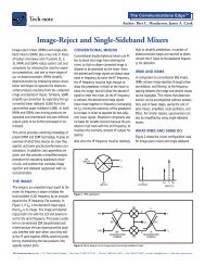
• Operating temperature range – <strong>SAW</strong> / <strong>STW</strong> oscillators exhibit a<br />
parabolic frequency versus temperature characteristic as shown in<br />
the figure below. <strong>STW</strong> devices have a similar characteristic but<br />
with a steeper slope on the parabola. This is by far the largest<br />
frequency budget component.<br />
• Aging – <strong>SAW</strong> / <strong>STW</strong> oscillators experience an exponential aging<br />
characteristic where the majority of aging occurs at the start of life<br />
and then approaches an assymptote.<br />
• Voltage pushing – This is a frequency shift caused by supply<br />
voltage shifts and ripple. Power supply characteristics should be<br />
included in a specification.<br />
• Load pulling – This is a frequency shift caused by VSWR interactions<br />
between the oscillator and its load. Load characteristics are<br />
included in some specifications expressed as a VSWR circle<br />
(magnitude and phase).<br />
• Set-on accuracy – This parameter represents the remainder of<br />
tuning bandwidth after the above have been considered. This<br />
number directly affects resonator yield but recall that adding<br />
bandwidth can some times jeopardize phase noise.<br />
Connecting the Digital World to the Global Network ®<br />
| www.triquint.com | © 9-12 <strong>TriQuint</strong> Semiconductor, Inc. | p.10<br />
+20<br />
0<br />
-20<br />
-40<br />
-60<br />
-80<br />
-100<br />
-120<br />
-140<br />
F = Frequency Deviation (Hz)<br />
F = Center Frequency (MHz)<br />
T = Temperature (ºC)<br />
To = Turnover Temperature<br />
(25ºC Nominal)<br />
2<br />
F T-To<br />
= - ppm<br />
F 5.4<br />
-50 -30 -10 +10 +30 +50 +70 +90<br />
Temperature (ºC)<br />
NOTE:<br />
Other turnover temperatures can be achieved for a<br />
given operating temperature range by choosing a<br />
different cut angle of quartz.<br />
Frequency Versus Temperature Curve
How to Specify <strong>Oscillators</strong><br />
Phase Noise / Jitter<br />
Phase noise is a measure of an oscillators spectral purity in an<br />
extremely short-term sense. Low frequency and thermal noise in a<br />
bandwidth determined by the resonator is integrated and causes<br />
small random carrier fluctuations. The resultant envelope of AM<br />
and PM sidebands is the phase noise skirt which is specified in<br />
terms of both an offset from the carrier and a dBc level in a 1 Hz<br />
bandwidth. AM sidebands are typically well below PM sidebands<br />
and as a result, PM noise is typically specified. The noise floor of<br />
the signal turns up into the phase noise skirt at an offset governed<br />
by resonator characteristics. In digital systems an emphasis is<br />
placed upon the time domain version of phase noise referred to as<br />
jitter. Jitter describes the fluctuations from ideality of a clock signal<br />
triggering edge in time (typically pSecs RMS).<br />
Typical phase noise curves for <strong>TriQuint</strong>’s standard product families<br />
are given in the appropriate sections. Ultra-low phase noise can<br />
be obtained on custom high-performance units. These highperformance<br />
units require specialized resonator and amplifier<br />
designs. Please contact <strong>TriQuint</strong>’s oscillator design engineers for<br />
more information.<br />
Dynamic Phase Noise / Microphonics<br />
For those customers that need good phase noise in challenging<br />
dynamic environments, <strong>TriQuint</strong> offers low g-sensitivity units as<br />
previously discussed. <strong>TriQuint</strong> routinely assists customers in<br />
determining an appropriate specification. Typically a plot of the<br />
vibration spectrum and a dynamic phase noise skirt description<br />
is needed to accurately determine the g-sensitivity specification.<br />
Please contact <strong>TriQuint</strong>’s oscillator design team for assistance.<br />
Harmonics<br />
<strong>SAW</strong> / <strong>STW</strong> oscillators do generate harmonics. Second and third<br />
harmonics are generally specified in terms of dBc. The majority<br />
of <strong>TriQuint</strong>’s oscillator generate frequencies fundamentally without<br />
the need for multiplication. As a result, fundamental oscillators<br />
have no subharmonics.<br />
Non-Harmonic Spurious<br />
There are no intrinsic generators of spurious in <strong>SAW</strong> / <strong>STW</strong><br />
oscillators; however, power supply ripple will induce cause<br />
spurious. As a result, it is necessary for our customers to specify<br />
the magnitude as well as the spectrum of supply ripple. This is<br />
particularly true for customers using switching power supplies.<br />
After review of a customer’s specification, <strong>TriQuint</strong> engineers can<br />
then advise them of the level of spurious that will be generated. In<br />
addition, <strong>TriQuint</strong> can guide customers towards models that have<br />
on-board regulation or can address custom designs.<br />
For Pricing Information<br />
Call <strong>TriQuint</strong> at 407-886-8860 for specifications or to place your<br />
order for any of the standard oscillators in the listing. However,<br />
if your requirements call for an oscillator between the operating<br />
frequencies of the standard parts or with custom requirements,<br />
please contact our oscillator engineering department.<br />
To the best of our knowledge, this information was correct at<br />
the time of printing. <strong>TriQuint</strong> reserves the right to modify these<br />
specifications when necessary to provide optimum performance<br />
and cost.<br />
Connecting the Digital World to the Global Network ®<br />
| www.triquint.com | © 9-12 <strong>TriQuint</strong> Semiconductor, Inc. | p.11
CONNECT WITH TRIQUINT.<br />
Phone: +1.407.886.8860<br />
Email: info-defense@tqs.com<br />
Visit www.triquint.com/subscribe and register<br />
for <strong>TriQuint</strong> product and process updates.<br />
Image Courtesy Jamie Hunter / Aviacom<br />
Connecting the Digital World<br />
to the Global Network ®