12. Spur Gear Design and selection Standard proportions Forces on ...
12. Spur Gear Design and selection Standard proportions Forces on ...
12. Spur Gear Design and selection Standard proportions Forces on ...

Create successful ePaper yourself
Turn your PDF publications into a flip-book with our unique Google optimized e-Paper software.
<str<strong>on</strong>g>12.</str<strong>on</strong>g> <str<strong>on</strong>g>Spur</str<strong>on</strong>g> <str<strong>on</strong>g>Gear</str<strong>on</strong>g> <str<strong>on</strong>g>Design</str<strong>on</strong>g> <str<strong>on</strong>g>and</str<strong>on</strong>g><br />
<str<strong>on</strong>g>selecti<strong>on</strong></str<strong>on</strong>g><br />
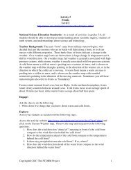
Objectives<br />
• Apply principles learned in Chapter 11 to actual design <str<strong>on</strong>g>and</str<strong>on</strong>g> <str<strong>on</strong>g>selecti<strong>on</strong></str<strong>on</strong>g> of spur<br />
gear systems.<br />
• Calculate forces <strong>on</strong> teeth of spur gears, including impact forces associated with<br />
velocity <str<strong>on</strong>g>and</str<strong>on</strong>g> clearances.<br />
• Determine allowable force <strong>on</strong> gear teeth, including the factors necessary due to<br />
angle of involute of tooth shape <str<strong>on</strong>g>and</str<strong>on</strong>g> materials selected for gears.<br />
• <str<strong>on</strong>g>Design</str<strong>on</strong>g> actual gear systems, including specifying materials, manufacturing<br />
accuracy, <str<strong>on</strong>g>and</str<strong>on</strong>g> other factors necessary for complete spur gear design.<br />
• Underst<str<strong>on</strong>g>and</str<strong>on</strong>g> <str<strong>on</strong>g>and</str<strong>on</strong>g> determine necessary surface hardness of gears to minimize or<br />
prevent surface wear.<br />
• Underst<str<strong>on</strong>g>and</str<strong>on</strong>g> how lubricati<strong>on</strong> can cushi<strong>on</strong> the impact <strong>on</strong> gearing systems <str<strong>on</strong>g>and</str<strong>on</strong>g> cool<br />
them.<br />
• Select st<str<strong>on</strong>g>and</str<strong>on</strong>g>ard gears available from stocking manufacturers or distributors.<br />
P N RAO 1<br />
Specificati<strong>on</strong>s for st<str<strong>on</strong>g>and</str<strong>on</strong>g>ard gear<br />
teeth<br />
Item<br />
Pressure<br />
angle<br />
Addendum<br />
(in.)<br />
Dedendum<br />
(in.)<br />
Full depth & pitches<br />
coarser than 20<br />
20°<br />
1.0/P<br />
1.250/P<br />
25°<br />
1.0/P<br />
1.250/P<br />
Full depth &<br />
pitches finer<br />
than 20<br />
20°<br />
1.0/P<br />
1.2/P + 0.002<br />
14½° full<br />
depth<br />
14½°<br />
1/P<br />
1.157/P<br />
P N RAO 3<br />
<str<strong>on</strong>g>Forces</str<strong>on</strong>g> <strong>on</strong> spur gear teeth<br />
• Power, P;<br />
T n<br />
or<br />
63,000 P<br />
P =<br />
T =<br />
63,000<br />
n<br />
• Torque, T = Ft r <str<strong>on</strong>g>and</str<strong>on</strong>g> r = Dp /2<br />
• Combining the above we can write<br />
F =<br />
t<br />
2 T<br />
D<br />
p<br />
P N RAO 5<br />
St<str<strong>on</strong>g>and</str<strong>on</strong>g>ard <str<strong>on</strong>g>proporti<strong>on</strong>s</str<strong>on</strong>g><br />
• American St<str<strong>on</strong>g>and</str<strong>on</strong>g>ard Associati<strong>on</strong> (ASA)<br />
• American <str<strong>on</strong>g>Gear</str<strong>on</strong>g> Manufacturers Associati<strong>on</strong><br />
(AGMA)<br />
• Brown <str<strong>on</strong>g>and</str<strong>on</strong>g> Sharp<br />
• 14 ½ deg; 20 deg; 25 deg pressure angle<br />
• Full depth <str<strong>on</strong>g>and</str<strong>on</strong>g> stub tooth systems<br />
P N RAO 2<br />
<str<strong>on</strong>g>Forces</str<strong>on</strong>g> <strong>on</strong> spur gear teeth<br />
• F t = Transmitted force<br />
• F n = Normal force or separating<br />
force<br />
• F r = Resultant force<br />
• θ = pressure angle<br />
•F n = F t tan θ<br />
F<br />
r =<br />
Ft<br />
cos θ<br />
P N RAO 4<br />
Example Problem 12-1: <str<strong>on</strong>g>Forces</str<strong>on</strong>g> <strong>on</strong> <str<strong>on</strong>g>Spur</str<strong>on</strong>g> <str<strong>on</strong>g>Gear</str<strong>on</strong>g> Teeth<br />
• 20-tooth, 8 pitch, 1-inch-wide, 20° pini<strong>on</strong><br />
transmits 5 hp at 1725 rpm to a 60-tooth gear.<br />
• Determine driving force, separating force, <str<strong>on</strong>g>and</str<strong>on</strong>g><br />
maximum force that would act <strong>on</strong> mounting<br />
shafts.<br />
P N RAO 6<br />
1
Example Problem 12-1: <str<strong>on</strong>g>Forces</str<strong>on</strong>g> <strong>on</strong> <str<strong>on</strong>g>Spur</str<strong>on</strong>g> <str<strong>on</strong>g>Gear</str<strong>on</strong>g> Teeth<br />
(2-6)<br />
P = Tn<br />
• 20-tooth, 8 pitch, 1-inch-wide, 20° pini<strong>on</strong> transmits 5 hp at 1725 rpm to a 60-tooth gear.<br />
• Determine driving force, separating force, <str<strong>on</strong>g>and</str<strong>on</strong>g> maximum force that would act <strong>on</strong><br />
mounting shafts.<br />
63,000<br />
− Find pitch circle:<br />
T = 63,000P<br />
n<br />
T = (63,000)5<br />
1725<br />
Dp = Np<br />
Pd<br />
= 183 in-lb<br />
20 teeth<br />
Dp =<br />
= 2.5 in<br />
8 teeth/in diameter<br />
(11-4)<br />
P N RAO 7<br />
Surface Speed<br />
• Surface speed (V m ) is often referred to as<br />
pitch-line speed<br />
π Dp<br />
n<br />
•Vm = ft/min<br />
12<br />
π D<br />
•Vm = p n<br />
m/min -- Metric units<br />
1000<br />
P N RAO 9<br />
Strength of <str<strong>on</strong>g>Gear</str<strong>on</strong>g> Teeth<br />
• Lewis form factor method<br />
P N RAO 11<br />
Example Problem 12-1: <str<strong>on</strong>g>Forces</str<strong>on</strong>g> <strong>on</strong> <str<strong>on</strong>g>Spur</str<strong>on</strong>g> <str<strong>on</strong>g>Gear</str<strong>on</strong>g> Teeth (c<strong>on</strong>t’d.)<br />
− Find transmitted force:<br />
Ft = 2T<br />
Dp<br />
(2)183 in-lb<br />
Ft = = 146 lb<br />
2.5 in<br />
− Find separating force:<br />
Fn = Ft tan θ<br />
Fn = 146 lb tan 20°<br />
Fn = 53 lb<br />
− Find maximum force:<br />
Vm = π D n<br />
or<br />
π Dp n<br />
Vm =<br />
12<br />
Fr = Ft<br />
cos θ<br />
146 lb<br />
Fr =<br />
cos 20°<br />
ft<br />
Vm = π 2.5 in 1725 rpm<br />
12 in<br />
Vm = 1129 ft/min<br />
(12-3)<br />
(12-1)<br />
(12-2)<br />
Fr = 155 lb<br />
P N RAO 8<br />
Example Problem 12-2: Surface Speed<br />
• In previous problem, determine the surface speed:<br />
(12-7)<br />
(12-5)<br />
P N RAO 10<br />
<str<strong>on</strong>g>Forces</str<strong>on</strong>g> <strong>on</strong> <str<strong>on</strong>g>Gear</str<strong>on</strong>g> Tooth<br />
Figure 14.20 <str<strong>on</strong>g>Forces</str<strong>on</strong>g> acting<br />
<strong>on</strong> individual gear tooth.<br />
©1998 McGraw-Hill, Hamrock,<br />
Jacobs<strong>on</strong> <str<strong>on</strong>g>and</str<strong>on</strong>g> Schmid<br />
P N RAO 12<br />
2
Lewis equati<strong>on</strong><br />
Sn<br />
Y b<br />
F s =<br />
P<br />
•F s = Allowable dynamic bending force (lb)<br />
•S n = Allowable stress (lb/in 2 ). Use<br />
endurance limit <str<strong>on</strong>g>and</str<strong>on</strong>g> account for the fillet as<br />
the stress c<strong>on</strong>centrati<strong>on</strong> factor<br />
• b = Face width (in.)<br />
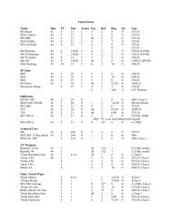
• Y = Lewis form factor (Table <str<strong>on</strong>g>12.</str<strong>on</strong>g>1)<br />
•P d = Diametral pitch<br />
d<br />
P N RAO 13<br />
Example Problem 12-3: Strength of <str<strong>on</strong>g>Gear</str<strong>on</strong>g> Teeth<br />
• In Example Problem 12-1, determine the force allowable (Fs ) <strong>on</strong> these teeth if the<br />
pini<strong>on</strong> is made from an AISI 4140 annealed steel, the mating gear is made from AISI<br />
1137 hot-rolled steel, <str<strong>on</strong>g>and</str<strong>on</strong>g> l<strong>on</strong>g life is desired.<br />
− Pini<strong>on</strong>:<br />
Sn = .5 Su = .5 (95 ksi) = 47.5 ksi<br />
(12-9)<br />
Sn b Y<br />
Fs =<br />
Pd<br />
− Find Lewis form factor (Y) from Table 12-1, assuming full-depth teeth:<br />
Y = .320<br />
47,500 (1) .320<br />
Fs =<br />
8<br />
Fs = 1900 lb<br />
P N RAO 15<br />
Classes of <str<strong>on</strong>g>Gear</str<strong>on</strong>g>s<br />
• Transmitted load depends <strong>on</strong> the accuracy of the<br />
gears<br />
• <str<strong>on</strong>g>Gear</str<strong>on</strong>g> Manufacture<br />
– Casting<br />
– Machining<br />
• Forming<br />
• Hobbing<br />
• Shaping <str<strong>on</strong>g>and</str<strong>on</strong>g> Planing<br />
– Forming<br />
– stamping<br />
P N RAO 17<br />
− <str<strong>on</strong>g>Gear</str<strong>on</strong>g>:<br />
Table <str<strong>on</strong>g>12.</str<strong>on</strong>g>1 Lewis form factors (Y)<br />
P N RAO 14<br />
Example Problem 12-3: Strength of <str<strong>on</strong>g>Gear</str<strong>on</strong>g> Teeth (c<strong>on</strong>t’d.)<br />
Sn = .5 (88 ksi) = 44 ksi<br />
Y = .421<br />
44,000 (1) .421<br />
Fs =<br />
8<br />
Fs = 2316 lb<br />
− Use Fs = 1900 lb for design purposes.<br />
(Table 12-1)<br />
P N RAO 16<br />
Force Transmitted<br />
• Transmitted load depends <strong>on</strong> the accuracy of the<br />
gears<br />
• A dynamic load factor is added to take care of<br />
this.<br />
• Ft = Transmitted force<br />
• Fd = Dynamic force<br />
• Commercial 600 + Vm<br />
Fd<br />
=<br />
Ft<br />
600<br />
P N RAO 18<br />
3
• Carefully cut<br />
• Precisi<strong>on</strong><br />
• Hobbed or shaved<br />
1 < N sf < 1.25<br />
1.25 < N sf < 1.5<br />
1.5 < N sf < 1.75<br />
1.75 < N sf < 2<br />
Classes of <str<strong>on</strong>g>Gear</str<strong>on</strong>g>s<br />
1200 + Vm<br />
Fd<br />
=<br />
1200<br />
78 + V<br />
Fd<br />
=<br />
78<br />
0.5<br />
m<br />
F<br />
t<br />
F<br />
50 + V<br />
Fd<br />
=<br />
50<br />
P N RAO 19<br />
t<br />
0.5<br />
m<br />
Table <str<strong>on</strong>g>12.</str<strong>on</strong>g>2 Service Factors<br />
Moderately heavy shock<br />
Heavy shock<br />
F<br />
Uniform load without shock<br />
Medium shock, frequent starts<br />
P N RAO 21<br />
Example Problem 12-4: <str<strong>on</strong>g>Design</str<strong>on</strong>g> Methods<br />
• If, in Example Problem 12-1, the gears are commercial grade, determine dynamic load<br />
<str<strong>on</strong>g>and</str<strong>on</strong>g>, based <strong>on</strong> force allowable from Example Problem 12-3, would this be an acceptable<br />
design if a factor of safety of 2 were desired?<br />
• Use surface speed <str<strong>on</strong>g>and</str<strong>on</strong>g> force transmitted from Example Problems 12-2 <str<strong>on</strong>g>and</str<strong>on</strong>g> 12-3.<br />
– Dynamic load:<br />
600 + Vm<br />
Fd<br />
= F<br />
(12-10)<br />
t<br />
600<br />
600 + 1129<br />
Fd<br />
=<br />
( 146 lb)<br />
600<br />
Fd<br />
= 421lb<br />
– Comparing to force allowable:<br />
Fs<br />
≥ Fd<br />
N sf<br />
1900 lb<br />
≥ 421<br />
2<br />
950 lb > 421 lb<br />
• This design meets the criteria.<br />
P N RAO 23<br />
t<br />
<str<strong>on</strong>g>Design</str<strong>on</strong>g> Methods<br />
• Strength of gear tooth should be greater<br />
than the dynamic force; F s ≥ F d<br />
• You should also include the factor of safety,<br />
N sf<br />
F<br />
≥<br />
N<br />
s Fd<br />
sf<br />
P N RAO 20<br />
Face width of <str<strong>on</strong>g>Gear</str<strong>on</strong>g>s<br />
• Relati<strong>on</strong> between the width of gears <str<strong>on</strong>g>and</str<strong>on</strong>g> the<br />
diametral pitch<br />
8<br />
P<br />
d<br />
< b <<br />
<str<strong>on</strong>g>12.</str<strong>on</strong>g>5<br />
P<br />
d<br />
P N RAO 22<br />
Example Problem 12-5: <str<strong>on</strong>g>Design</str<strong>on</strong>g> Methods<br />
• <str<strong>on</strong>g>Spur</str<strong>on</strong>g> gears from the catalog page shown in Figure 12-3 are made from a .2% carb<strong>on</strong><br />
steel with no special heat treatment.<br />
• What factor of safety do they appear to use in this catalog?<br />
• Try a 24-tooth at 1800 rpm gear for example purposes.<br />
• From Appendix 4, an AISI 1020 hot-rolled steel would have .2% carb<strong>on</strong> with an Sy = 30<br />
ksi <str<strong>on</strong>g>and</str<strong>on</strong>g> Su = 55 ksi.<br />
− Therefore:<br />
− Find Dp :<br />
Sn = .5 Su<br />
Sn = .5 (55 ksi) = 27.5 ksi<br />
Dp = Np<br />
Pd<br />
(11-4)<br />
Dp =<br />
P N RAO 24<br />
24<br />
= 2 in<br />
12<br />
4
Example Problem 12-5: <str<strong>on</strong>g>Design</str<strong>on</strong>g> Methods (c<strong>on</strong>t’d)<br />
− Find Vm :<br />
− Find Fs :<br />
− Compared to catalog:<br />
π Dp n<br />
Vm =<br />
12<br />
ft<br />
Vm = π 2 in (1800 rpm)<br />
12 in<br />
Vm = 942 ft/min<br />
Sn b Y<br />
Fs =<br />
Pd<br />
Y = .302<br />
27,500 (¾) .302<br />
Fs =<br />
12<br />
(12-5)<br />
(12-9)<br />
(from Table 12-1)<br />
Fs = 519 lb<br />
P N RAO 25<br />
Example Problem 12-5: <str<strong>on</strong>g>Design</str<strong>on</strong>g> Methods (c<strong>on</strong>t’d)<br />
Nsf =<br />
hp - calculated<br />
hp - catalog<br />
Nsf = 5.8<br />
= 1.4<br />
4.14<br />
• Appears to be reas<strong>on</strong>able value.<br />
• Manufacturer may also have reduced its rating for wear purposes as these<br />
are not hardened gears.<br />
− Surface speed:<br />
P N RAO 27<br />
Example Problem 12-6: <str<strong>on</strong>g>Design</str<strong>on</strong>g> Methods (c<strong>on</strong>t’d.)<br />
π Dp n<br />
Vm =<br />
12<br />
4 in 900 rpm<br />
Vm = π<br />
12 in/ft<br />
Vm = 943 ft/min<br />
− Finding force <strong>on</strong> teeth:<br />
33,000 hp<br />
Ft =<br />
Vm<br />
33,000 (2)<br />
Ft =<br />
943<br />
(12-5)<br />
(12-6)<br />
Ft = 70 lb<br />
P N RAO 29<br />
Example Problem 12-5: <str<strong>on</strong>g>Design</str<strong>on</strong>g> Methods (c<strong>on</strong>t’d)<br />
− Set Fs = Fd <str<strong>on</strong>g>and</str<strong>on</strong>g> solve for Ft :<br />
Fd = Fs = ⎜<br />
⎝<br />
P N RAO 26<br />
⎛ 600 + Vm ⎞<br />
⎟ Ft<br />
600 ⎠<br />
519 lb = ⎜<br />
⎝ ⎛ 600 + 942 ⎞<br />
⎟ Ft<br />
600 ⎠<br />
Ft = 202 lb<br />
(12-3)<br />
T = F ⎜<br />
⎝ ⎛ ⎞<br />
⎟<br />
⎠<br />
Dp<br />
2<br />
T = 202 lb ⎜<br />
⎝ ⎛ 2 in ⎞<br />
2<br />
⎟<br />
⎠<br />
T = 202 in-lb<br />
(2-6)<br />
P = Tn 202 (1800)<br />
= = 5.8 hp<br />
63,000 63,000<br />
or<br />
(12-6)<br />
Ft Vm 202 (942)<br />
P = = = 5.8 hp<br />
33,000 33,000<br />
Example Problem 12-6: <str<strong>on</strong>g>Design</str<strong>on</strong>g> Methods<br />
• Pair of commercial-grade spur gears is to transmit 2 hp at a speed of 900 rpm of the<br />
pini<strong>on</strong> <str<strong>on</strong>g>and</str<strong>on</strong>g> 300 rpm for gear.<br />
• If class 30 cast ir<strong>on</strong> is to be used, specify a possible design for this problem.<br />
• The following variables are unknown: P d , D p , b, N t , N sf , θ.<br />
• As it is impossible to solve for all simultaneously, try the following:<br />
– P d = 12, N t = 48, θ = 14½°, N sf = 2<br />
– Solve for face width b.<br />
− Miscellaneous properties:<br />
Dp = Np 48<br />
= = 4 in<br />
Pd 12<br />
Ng = Np Vr = 48(3) = 144 teeth<br />
(11-4)<br />
P N RAO 28<br />
Example Problem 12-6: <str<strong>on</strong>g>Design</str<strong>on</strong>g> Methods (c<strong>on</strong>t’d.)<br />
– Dynamic force<br />
– Since width b is the unkown:<br />
⎛ 600 + Vm<br />
⎞<br />
Fd<br />
= ⎜ ⎟ Ft<br />
⎝ 600 ⎠<br />
⎛ 600 + 943 ⎞<br />
Fd<br />
= ⎜ ⎟ 70<br />
⎝ 600 ⎠<br />
Fd<br />
= 180 lb<br />
Fs<br />
≥ Fd<br />
N sf<br />
<str<strong>on</strong>g>and</str<strong>on</strong>g><br />
Sn<br />
b Y<br />
Fs<br />
=<br />
Pd<br />
Sn<br />
b Y<br />
= Fd<br />
N sf Pd<br />
(12-10)<br />
(12-8)<br />
–Class 30 CI; Su = 30 ksi; Sn = .4 Su (.4 is used because cast ir<strong>on</strong>):<br />
–Sn = 12 ksi<br />
–Y = .344<br />
(Table 12-1)<br />
P N RAO 30<br />
5
Example Problem 12-6: <str<strong>on</strong>g>Design</str<strong>on</strong>g> Methods (c<strong>on</strong>t’d.)<br />
− Substituting:<br />
Sn b Y<br />
= Fd<br />
Nsf Pd<br />
12,000 b .344<br />
= 180<br />
2 (12)<br />
b = 1.0 inches<br />
− Check ratio of width to pitch:<br />
8 <str<strong>on</strong>g>12.</str<strong>on</strong>g>5<br />
< b <<br />
Pd Pd<br />
8 <str<strong>on</strong>g>12.</str<strong>on</strong>g>5<br />
< 1 <<br />
12 12<br />
.66 < 1 < 1.04<br />
• This is an acceptable design.<br />
• Many other designs are also possible.<br />
P N RAO 31<br />
(12-9)<br />
(12-14)<br />
Buckingham Method of <str<strong>on</strong>g>Gear</str<strong>on</strong>g> <str<strong>on</strong>g>Design</str<strong>on</strong>g><br />
• It offers greater flexibility<br />
• Expected error is based <strong>on</strong> different-pitch<br />
teeth<br />
• More c<strong>on</strong>servative design<br />
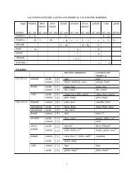
Material<br />
P N RAO 33<br />
Table <str<strong>on</strong>g>12.</str<strong>on</strong>g>3 Values of C for e = 0.001 inch<br />
Gray ir<strong>on</strong> <str<strong>on</strong>g>and</str<strong>on</strong>g> Gray ir<strong>on</strong><br />
Gray ir<strong>on</strong> <str<strong>on</strong>g>and</str<strong>on</strong>g> steel<br />
Steel <str<strong>on</strong>g>and</str<strong>on</strong>g> steel<br />
14 ½ deg<br />
800<br />
1,100<br />
1,600<br />
20 deg<br />
830<br />
1,140<br />
1,660<br />
P N RAO 35<br />
• To increase the dynamic beam strength of<br />
the gear<br />
– Increase tooth size by decreasing the<br />
diametral pitch<br />
– Increase face width upto the pitch diameter<br />
of the pini<strong>on</strong><br />
– Select material of greater endurance limit<br />
– Machine tooth profiles more precisely<br />
– Mount gears more precisely<br />
– Use proper lubricant <str<strong>on</strong>g>and</str<strong>on</strong>g> reduce<br />
c<strong>on</strong>taminati<strong>on</strong><br />
P N RAO 32<br />
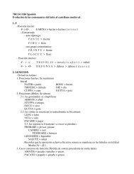
Fig. <str<strong>on</strong>g>12.</str<strong>on</strong>g>4 Expected error in tooth profiles<br />
P N RAO 34<br />
Buckingham Method of <str<strong>on</strong>g>Gear</str<strong>on</strong>g> <str<strong>on</strong>g>Design</str<strong>on</strong>g><br />
0.05 Vm<br />
(bC<br />
+ F )<br />
Fd<br />
=<br />
Ft<br />
+<br />
0.05 V + (bC<br />
+ F<br />
m<br />
t<br />
0.5<br />
t )<br />
P N RAO 36<br />
6
Fig. <str<strong>on</strong>g>12.</str<strong>on</strong>g>5 Recommended maximum error in gear teeth<br />
− Find torque:<br />
P N RAO 37<br />
Example Problem 12-7: Buckingham Method of <str<strong>on</strong>g>Gear</str<strong>on</strong>g><br />
<str<strong>on</strong>g>Design</str<strong>on</strong>g> <str<strong>on</strong>g>and</str<strong>on</strong>g> Expected Error (c<strong>on</strong>t’d.)<br />
P = Tn<br />
63,000<br />
P (63,000)<br />
T =<br />
n<br />
3 (63,000)<br />
T =<br />
3450<br />
T = 55 in-lb<br />
− Find force transmitted:<br />
Ft = 2T<br />
Dp<br />
2(55 in-lb)<br />
Ft =<br />
1.5 in<br />
Ft = 73 lb<br />
P N RAO 39<br />
Example Problem 12-7: Buckingham Method of <str<strong>on</strong>g>Gear</str<strong>on</strong>g><br />
<str<strong>on</strong>g>Design</str<strong>on</strong>g> <str<strong>on</strong>g>and</str<strong>on</strong>g> Expected Error (c<strong>on</strong>t’d.)<br />
• Expected error from Figure 12-4:<br />
e = .0005<br />
• The value of C from Table 12-3 for steel <str<strong>on</strong>g>and</str<strong>on</strong>g> steel <str<strong>on</strong>g>and</str<strong>on</strong>g> 20° involute angle gears is 1660:<br />
C = .0005 (1000) 1660<br />
C = 830<br />
• Solve for dynamic load using Buckingham’s equati<strong>on</strong>:<br />
• This meets the criteria.<br />
(2-6)<br />
(12-3)<br />
. 05Vm<br />
( bC<br />
+ Ft<br />
)<br />
F d = Ft<br />
+<br />
1/<br />
2<br />
(12-15)<br />
. 05 Vm<br />
+ ( bC + Ft<br />
)<br />
. 05 ( 1355)<br />
( 1•<br />
830 + 73)<br />
Fd<br />
= 73 +<br />
1/<br />
2<br />
. 05 ( 1355)<br />
+ ( 1 • 830 + 73)<br />
Fd<br />
= 699 lb<br />
Fs<br />
≥ Fd<br />
N sf<br />
1000<br />
≥ 699<br />
1.<br />
4<br />
714 > 699<br />
P N RAO 41<br />
Example Problem 12-7: Buckingham Method of <str<strong>on</strong>g>Gear</str<strong>on</strong>g><br />
<str<strong>on</strong>g>Design</str<strong>on</strong>g> <str<strong>on</strong>g>and</str<strong>on</strong>g> Expected Error<br />
• A pair of steel gears is made from annealed AISI 3140.<br />
• Each gear has a surface hardness of BHN = 350.<br />
• The pini<strong>on</strong> is a precisi<strong>on</strong>, 16 pitch, 20° involute, with 24 teeth 1 inch wide.<br />
• The gear has 42 teeth.<br />
• To transmit 3 hp at a speed of 3450 rpm for a safety factor of 1.4, is this a<br />
suitable design?<br />
Su = 95 ksi<br />
Sn = .5 Su = .5(95 ksi) = 47.5 ksi<br />
Dp = Np<br />
Pd<br />
− Find surface speed:<br />
24<br />
= = 1.5 in<br />
16<br />
(Appendix 4)<br />
(11-4)<br />
P N RAO 38<br />
Example Problem 12-7: Buckingham Method of <str<strong>on</strong>g>Gear</str<strong>on</strong>g><br />
<str<strong>on</strong>g>Design</str<strong>on</strong>g> <str<strong>on</strong>g>and</str<strong>on</strong>g> Expected Error (c<strong>on</strong>t’d.)<br />
π Dp n<br />
Vm =<br />
12<br />
π 1.5 in 3450 rpm<br />
Vm =<br />
12 ft/in<br />
Vm = 1355 ft/min<br />
− Find force allowable (Fs):<br />
Sn b Y<br />
Fs =<br />
Pd<br />
Y = .337<br />
47,500 (1) .337<br />
Fs =<br />
16<br />
(12-5)<br />
(12-9)<br />
(from Table 12-1)<br />
Fs = 1000<br />
P N RAO 40<br />
Wear strength (Buckingham)<br />
⎛ 2 D ⎞ g<br />
F<br />
⎜ ⎟<br />
W = DP<br />
b Kg<br />
⎜ ⎟<br />
⎝ Dp<br />
+ Dg<br />
⎠<br />
Fw = tooth wear strength (lb)<br />
Dp = diametral pitch of pini<strong>on</strong> (in.)<br />
Dg = diametral pitch of gear (in.)<br />
b = face width (in.)<br />
Kg = load stress factor (Appendix 13)<br />
P N RAO 42<br />
7
Example Problem 12-8: Wear of <str<strong>on</strong>g>Gear</str<strong>on</strong>g>s<br />
• In prior example problem, verify the surface is suitable for wear c<strong>on</strong>siderati<strong>on</strong>s.<br />
For wear use N ss = 1.2<br />
− Wear formula:<br />
− Find Q :<br />
Fw = Dp b Q Kg<br />
2 Ng<br />
Q =<br />
Ng + Np<br />
2 (42)<br />
Q =<br />
42 + 24<br />
Q = 1.27<br />
Kg = 270<br />
(12-16)<br />
(12-17)<br />
(from Appendix 13)<br />
P N RAO 43<br />
Example Problem 12-8: Wear of <str<strong>on</strong>g>Gear</str<strong>on</strong>g>s (c<strong>on</strong>t’d.)<br />
– Substituting into equati<strong>on</strong> 12-16:<br />
Fw<br />
= 1.<br />
5 ( 1)<br />
1.<br />
27 ( 270)<br />
Fw<br />
= 514<br />
• This would not be suitable. Try if surfaces each had a BHN = 450.<br />
K g = 470<br />
(from Appendix 13)<br />
Fw<br />
= 1.<br />
5 ( 1)<br />
( 1.<br />
27)<br />
( 470)<br />
Fw<br />
= 895<br />
Fw<br />
≥ Fd<br />
N sf<br />
895<br />
> 699<br />
1.<br />
2<br />
746 > 699<br />
• This would now be acceptable if the gear teeth were hardened to a BHN of 450.<br />
P N RAO 44<br />
8