Operating Instructions For The Auxiliary Idle Control ... - Ford Fleet
Operating Instructions For The Auxiliary Idle Control ... - Ford Fleet
Operating Instructions For The Auxiliary Idle Control ... - Ford Fleet

Create successful ePaper yourself
Turn your PDF publications into a flip-book with our unique Google optimized e-Paper software.
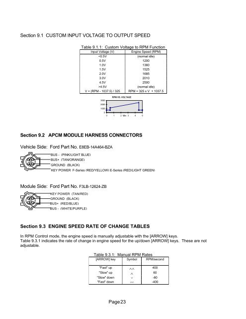
Section 9.1 CUSTOM INPUT VOLTAGE TO OUTPUT SPEED<br />
Table 9.1.1: Custom Voltage to RPM Function<br />
Input Voltage (V) Engine Speed (RPM)<br />
4.5V (normal idle)<br />
V = (RPM - 1037.5) / 325 RPM = 325 x V + 1037.5<br />
3000<br />
2000<br />
1000<br />
0<br />
RPM VS. VOLTAGE<br />
0 1 2 Vin 3 4 5<br />
Section 9.2 APCM MODULE HARNESS CONNECTORS<br />
Vehicle Side: <strong>For</strong>d Part No. E8EB-14A464-BZA<br />
BUS - (PINK/LIGHT BLUE)<br />
BUS+ (TAN/ORANGE)<br />
GROUND (BLACK)<br />
KEY POWER F-Series (RED/YELLOW) E-Series (RED/LIGHT GREEN)<br />
Module Side: <strong>For</strong>d Part No. F3LB-12624-ZB<br />
KEY POWER (TAN/RED)<br />
GROUND (BLACK)<br />
BUS+ (RED/BLUE)<br />
BUS - (WHITE/PURPLE)<br />
Section 9.3 ENGINE SPEED RATE OF CHANGE TABLES<br />
In RPM <strong>Control</strong> mode, the engine speed is manually adjustable with the [ARROW] keys.<br />
Table 9.3.1 indicates the rate of change in engine speed for the up/down [ARROW] keys. <strong>The</strong>se are not<br />
adjustable.<br />
Table 9.3.1: Manual RPM Rates<br />
[ARROW] key Symbol RPM/second<br />
"Fast" up ∧∧ 400<br />
"Slow" up ∧ 60<br />
"Slow" down ∨ -60<br />
"Fast" down ∨∨ -400<br />
Page 23