Operating Instructions For The Auxiliary Idle Control ... - Ford Fleet
Operating Instructions For The Auxiliary Idle Control ... - Ford Fleet
Operating Instructions For The Auxiliary Idle Control ... - Ford Fleet

You also want an ePaper? Increase the reach of your titles
YUMPU automatically turns print PDFs into web optimized ePapers that Google loves.
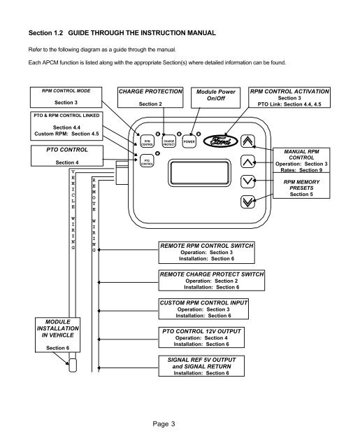
Section 1.2 GUIDE THROUGH THE INSTRUCTION MANUAL<br />
Refer to the following diagram as a guide through the manual.<br />
Each APCM function is listed along with the appropriate Section(s) where detailed information can be found.<br />
RPM CONTROL MODE<br />
Section 3<br />
PTO & RPM CONTROL LINKED<br />
Section 4.4<br />
Custom RPM: Section 4.5<br />
PTO CONTROL<br />
Section 4<br />
V<br />
E<br />
H<br />
I<br />
C<br />
L<br />
E<br />
W<br />
I<br />
R<br />
I<br />
N<br />
G<br />
MODULE<br />
INSTALLATION<br />
IN VEHICLE<br />
Section 6<br />
R<br />
E<br />
M<br />
O<br />
T<br />
E<br />
W<br />
I<br />
R<br />
I<br />
N<br />
G<br />
CHARGE PROTECTION<br />
Section 2<br />
RPM<br />
CONTROL<br />
PTO<br />
CONTROL<br />
CHARGE<br />
PROTECT<br />
Page 3<br />
POWER<br />
Module Power<br />
On/Off<br />
REMOTE RPM CONTROL SWITCH<br />
Operation: Section 3<br />
Installation: Section 6<br />
REMOTE CHARGE PROTECT SWITCH<br />
Operation: Section 2<br />
Installation: Section 6<br />
CUSTOM RPM CONTROL INPUT<br />
Operation: Section 3<br />
Installation: Section 6<br />
PTO CONTROL 12V OUTPUT<br />
Operation: Section 4<br />
Installation: Section 6<br />
SIGNAL REF 5V OUTPUT<br />
and SIGNAL RETURN<br />
Installation: Section 6<br />
RPM CONTROL ACTIVATION<br />
Section 3<br />
PTO Link: Section 4.4, 4.5<br />
MANUAL RPM<br />
CONTROL<br />
Operation: Section 3<br />
Rates: Section 9<br />
RPM MEMORY<br />
PRESETS<br />
Section 5