

CHAPTER 2 THEORY OF OPERATION - Snap-on Equipment
CHAPTER 2 THEORY OF OPERATION - Snap-on Equipment
CHAPTER 2 THEORY OF OPERATION - Snap-on Equipment

You also want an ePaper? Increase the reach of your titles
YUMPU automatically turns print PDFs into web optimized ePapers that Google loves.
<str<strong>on</strong>g>CHAPTER</str<strong>on</strong>g> 2<br />
<str<strong>on</strong>g>THEORY</str<strong>on</strong>g> <str<strong>on</strong>g>OF</str<strong>on</strong>g> <str<strong>on</strong>g>OPERATION</str<strong>on</strong>g><br />
DESCRIPTION <str<strong>on</strong>g>OF</str<strong>on</strong>g> OPERATING CYCLES<br />
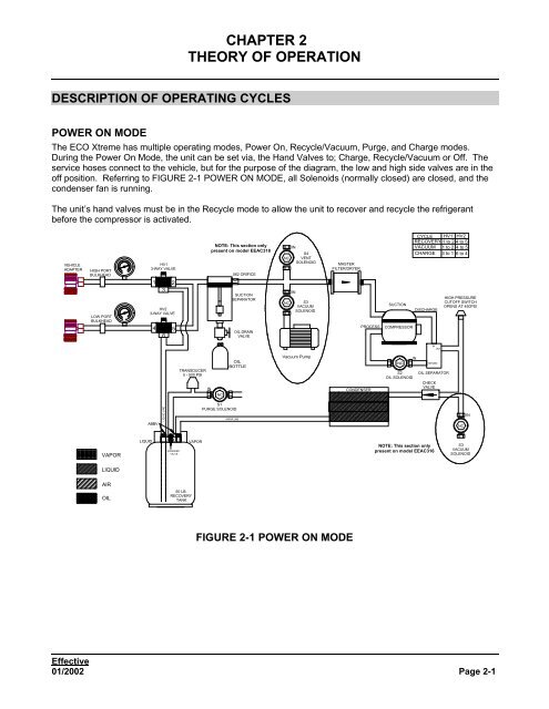
POWER ON MODE<br />
The ECO Xtreme has multiple operating modes, Power On, Recycle/Vacuum, Purge, and Charge modes.<br />
During the Power On Mode, the unit can be set via, the Hand Valves to; Charge, Recycle/Vacuum or Off. The<br />
service hoses c<strong>on</strong>nect to the vehicle, but for the purpose of the diagram, the low and high side valves are in the<br />
off positi<strong>on</strong>. Referring to FIGURE 2-1 POWER ON MODE, all Solenoids (normally closed) are closed, and the<br />
c<strong>on</strong>denser fan is running.<br />
The unit’s hand valves must be in the Recycle mode to allow the unit to recover and recycle the refrigerant<br />
before the compressor is activated.<br />
VEHICLE<br />
ADAPTER<br />
HIGH PORT<br />
BULKHEAD<br />
LOW PORT<br />
BULKHEAD<br />
VAPOR<br />
LIQUID<br />
AIR<br />
OIL<br />
0<br />
10 20<br />
0<br />
30<br />
500<br />
120<br />
HV1<br />
3-WAY VALVE<br />
1<br />
3<br />
LIQUID LINE<br />
2<br />
HV2<br />
3-WAY VALVE<br />
4 5<br />
6<br />
ABBV<br />
LIQUID VAPOR<br />
SCHRADER<br />
VALVE<br />
TRANSDUCER<br />
0 - 500 PSI<br />
50 LB.<br />
RECOVERY<br />
TANK<br />
IN<br />
NOTE: This secti<strong>on</strong> <strong>on</strong>ly<br />
present <strong>on</strong> model EEAC318<br />
NC<br />
S1<br />
PURGE SOLENOID<br />
.062 ORIFICE<br />
SUCTION<br />
SEPARATOR<br />
VAPOR LINE<br />
OIL DRAIN<br />
VALVE<br />
OIL<br />
BOTTLE<br />
MASTER<br />
FILTER/DRYER<br />
FIGURE 2-1 POWER ON MODE<br />
COMPRESSOR<br />
S2<br />
OIL SOLENOID<br />
DISCHARGE<br />
Effective<br />
01/2002 Page 2-1<br />
NC<br />
NC<br />
IN<br />
IN<br />
S4<br />
VENT<br />
SOLENOID<br />
S3<br />
VACUUM<br />
SOLENOID<br />
Vacuum Pump<br />
PROCESS<br />
CONDENSER<br />
SUCTION<br />
NC<br />
CYCLE HV1 HV2<br />
RECOVERY 1 to 2 4 to 5<br />
VACUUM 1 to 2 4 to 5<br />
CHARGE 3 to 1 6 to 4<br />
IN<br />
IN<br />
OUT<br />
RETURN<br />
OIL SEPARATOR<br />
CHECK<br />
VALVE<br />
NOTE: This secti<strong>on</strong> <strong>on</strong>ly<br />
present <strong>on</strong> model EEAC316<br />
HIGH PRESSURE<br />
CUT<str<strong>on</strong>g>OF</str<strong>on</strong>g>F SWITCH<br />
OPENS AT 450PSI<br />
NC<br />
IN<br />
S3<br />
VACUUM<br />
SOLENOID
<str<strong>on</strong>g>CHAPTER</str<strong>on</strong>g> 2 <str<strong>on</strong>g>THEORY</str<strong>on</strong>g> <str<strong>on</strong>g>OF</str<strong>on</strong>g> <str<strong>on</strong>g>OPERATION</str<strong>on</strong>g><br />
RECYCLE MODE<br />
VEHICLE<br />
ADAPTER<br />
HIGH PORT<br />
BULKHEAD<br />
LOW PORT<br />
BULKHEAD<br />
VAPOR<br />
LIQUID<br />
AIR<br />
OIL<br />
0<br />
10 20<br />
0<br />
30<br />
500<br />
120<br />
HV1<br />
3-WAY VALVE<br />
1<br />
3<br />
LIQUID LINE<br />
2<br />
HV2<br />
3-WAY VALVE<br />
4 5<br />
6<br />
ABBV<br />
LIQUID VAPOR<br />
SCHRADER<br />
VALVE<br />
TRANSDUCER<br />
0 - 500 PSI<br />
50 LB.<br />
RECOVERY<br />
TANK<br />
IN<br />
NOTE: This secti<strong>on</strong> <strong>on</strong>ly<br />
present <strong>on</strong> model EEAC318<br />
NC<br />
S1<br />
PURGE SOLENOID<br />
.062 ORIFICE<br />
SUCTION<br />
SEPARATOR<br />
VAPOR LINE<br />
OIL DRAIN<br />
VALVE<br />
OIL<br />
BOTTLE<br />
MASTER<br />
FILTER/DRYER<br />
FIGURE 2-2 RECYCLE MODE<br />
COMPRESSOR<br />
S2<br />
OIL SOLENOID<br />
DISCHARGE<br />
During the Recycle mode, the unit will pull all refrigerant from the vehicle, clean it, and store it in the recovery<br />
tank. To start the sequence, turn the unit’s hand valves to the Recycle positi<strong>on</strong>. Program the unit to<br />
recycle. The Compressor starts, which takes between 5 to 10 sec<strong>on</strong>ds. Once the compressor starts, refrigerant<br />
will enter the Sucti<strong>on</strong> Separator assembly in a liquid or vapor state, but will exit in a vapor state. The refrigerant<br />
will pass through the Master Filter/Dryer to be dried/cleaned of all moisture and processed through the<br />
compressor.<br />
Refrigerant then enters the oil separator to separate the oil that is used to lubricate the compressor. Refrigerant<br />
then exits the oil separator and flows through a check valve to allow the refrigerant to enter the c<strong>on</strong>denser.<br />
Refrigerant is then cooled using a fan and changed from a high-pressure vapor to a high-pressure liquid as it<br />
passes through the c<strong>on</strong>denser. The final stage captures the refrigerant in the Recovery Tank. At the end of the<br />
Recover Mode, the gauge set will indicate approximately 15” of vacuum. The operator must turn the unit hand<br />
valves <str<strong>on</strong>g>OF</str<strong>on</strong>g>F. The operator should m<strong>on</strong>itor the low side gauge for residual pressure buildup. Refer to Appendix<br />
C, Users Manual for more Informati<strong>on</strong>.<br />
NOTE If the Recovery Tank becomes full at any time during the Recycle Mode, an LED will flash and<br />
an error message will be displayed.<br />
Effective<br />
Page 2-2 01/2002<br />
NC<br />
NC<br />
IN<br />
IN<br />
S4<br />
VENT<br />
SOLENOID<br />
S3<br />
VACUUM<br />
SOLENOID<br />
Vacuum Pump<br />
PROCESS<br />
CONDENSER<br />
SUCTION<br />
NC<br />
CYCLE HV1 HV2<br />
RECOVERY 1 to 2 4 to 5<br />
VACUUM 1 to 2 4 to 5<br />
CHARGE 3 to 1 6 to 4<br />
IN<br />
IN<br />
OUT<br />
RETURN<br />
OIL SEPARATOR<br />
CHECK<br />
VALVE<br />
NOTE: This secti<strong>on</strong> <strong>on</strong>ly<br />
present <strong>on</strong> model EEAC316<br />
HIGH PRESSURE<br />
CUT<str<strong>on</strong>g>OF</str<strong>on</strong>g>F SWITCH<br />
OPENS AT 450PSI<br />
NC<br />
IN<br />
S3<br />
VACUUM<br />
SOLENOID
PURGE MODE<br />
<str<strong>on</strong>g>CHAPTER</str<strong>on</strong>g> 2 <str<strong>on</strong>g>THEORY</str<strong>on</strong>g> <str<strong>on</strong>g>OF</str<strong>on</strong>g> <str<strong>on</strong>g>OPERATION</str<strong>on</strong>g><br />
Since Tank Temperature is directly proporti<strong>on</strong>al to Tank Pressure, a Temperature probe held against the<br />
Recovery Tank is used to m<strong>on</strong>itor tank temperature. The Temperature Sensor and Pressure Transducer are<br />
m<strong>on</strong>itored before and after a Recovery. If needed, a Purge cycle is executed to release n<strong>on</strong>-c<strong>on</strong>densable (AIR)<br />
that may have been recovered al<strong>on</strong>g with the refrigerant. The unit m<strong>on</strong>itors and releases n<strong>on</strong>-c<strong>on</strong>densable<br />
(AIR) until the pressure is correct (or proporti<strong>on</strong>al) to the current tank temperature.<br />
N<strong>on</strong>-c<strong>on</strong>densable gases are released through S1 solenoid, which has a 1/32 orifice to reduce flow and ensure<br />
refrigerant is not lost. This sequence will repeat until the proper pressure is established.<br />
Special C<strong>on</strong>siderati<strong>on</strong>:<br />
At any time during the Recover Mode, the unit may display High Pressure. If the High Pressure light illuminates,<br />
then either the red recover tank valve is turned off or the unit must be purged to release the n<strong>on</strong>-c<strong>on</strong>densable<br />
gas. Refer to the User’s Manual in Appendix C for more informati<strong>on</strong>.<br />
VEHICLE<br />
ADAPTER<br />
HIGH PORT<br />
BULKHEAD<br />
LOW PORT<br />
BULKHEAD<br />
VAPOR<br />
LIQUID<br />
AIR<br />
OIL<br />
0<br />
10 20<br />
0<br />
30<br />
500<br />
120<br />
HV1<br />
3-WAY VALVE<br />
1<br />
3<br />
LIQUID LINE<br />
2<br />
HV2<br />
3-WAY VALVE<br />
4 5<br />
6<br />
ABBV<br />
LIQUID VAPOR<br />
SCHRADER<br />
VALVE<br />
TRANSDUCER<br />
0 - 500 PSI<br />
50 LB.<br />
RECOVERY<br />
TANK<br />
NOTE: This secti<strong>on</strong> <strong>on</strong>ly<br />
present <strong>on</strong> model EEAC318<br />
IN<br />
NC<br />
S1<br />
PURGE SOLENOID<br />
.062 ORIFICE<br />
SUCTION<br />
SEPARATOR<br />
VAPOR LINE<br />
OIL DRAIN<br />
VALVE<br />
OIL<br />
BOTTLE<br />
FIGURE 2-3 PURGE MODE<br />
MASTER<br />
FILTER/DRYER<br />
COMPRESSOR<br />
S2<br />
OIL SOLENOID<br />
DISCHARGE<br />
Effective<br />
01/2002 Page 2-3<br />
NC<br />
NC<br />
IN<br />
IN<br />
S4<br />
VENT<br />
SOLENOID<br />
S3<br />
VACUUM<br />
SOLENOID<br />
Vacuum Pump<br />
PROCESS<br />
CONDENSER<br />
SUCTION<br />
NC<br />
CYCLE HV1 HV2<br />
RECOVERY 1 to 2 4 to 5<br />
VACUUM 1 to 2 4 to 5<br />
CHARGE 3 to 1 6 to 4<br />
IN<br />
IN<br />
OUT<br />
RETURN<br />
OIL SEPARATOR<br />
CHECK<br />
VALVE<br />
NOTE: This secti<strong>on</strong> <strong>on</strong>ly<br />
present <strong>on</strong> model EEAC316<br />
HIGH PRESSURE<br />
CUT<str<strong>on</strong>g>OF</str<strong>on</strong>g>F SWITCH<br />
OPENS AT 450PSI<br />
NC<br />
IN<br />
S3<br />
VACUUM<br />
SOLENOID
<str<strong>on</strong>g>CHAPTER</str<strong>on</strong>g> 2 <str<strong>on</strong>g>THEORY</str<strong>on</strong>g> <str<strong>on</strong>g>OF</str<strong>on</strong>g> <str<strong>on</strong>g>OPERATION</str<strong>on</strong>g><br />
VACUUM MODE<br />
The Vacuum Mode is initiated when the operator programs the unit to pull a vacuum from the vehicle using the<br />
ECO Xtreme. When the unit is set to Vacuum Mode and both hand valves are in the positi<strong>on</strong>. The unit<br />
will then turn the compressor ON (Vacuum Pump for the EEAC318). Once the compressor (pump) starts it will<br />
pull a deep vacuum from 25" Hg to 29" Hg. The pressure from the discharge side of the compressor is vented<br />
to atmosphere via S3 solenoid (in the EEAC318 solenoid S3 provides a path to the Vacuum Pump). During this<br />
process in the Model EEAC316, some oil from the compressor might escape, but is trapped in the bottom of the<br />
Compressor Oil Separator. At the end of the Vacuum cycle, the Oil Solenoid (S2) will open allowing the vacuum<br />
from the compressor to pull the oil back to the compressor.<br />
Special C<strong>on</strong>siderati<strong>on</strong>:<br />
In the Model EEAC318 the Vacuum Pump may require up to 60 sec<strong>on</strong>ds to restart if power is cycled quickly.<br />
Also, the Vacuum Pump will automatically shut down if it does not pull 15”Hg in 2.5 minutes. This is to prevent<br />
oil loss.<br />
!<br />
DURING A VACUUM MODE THE OUTPUT <str<strong>on</strong>g>OF</str<strong>on</strong>g> EITHER THE COMPRESSOR (EEAC316) OR THE VACUUM<br />
PUMP (EEAC318) IS VENTED TO ATMOSPHERE. PERFORMING A VACUUM ON A VEHICLE THAT HAS<br />
REFRIGERANT IN THE SYSTEM WILL VENT THAT REFRIGERANT TO ATMOSPHERE.<br />
VEHICLE<br />
ADAPTER<br />
HIGH PORT<br />
BULKHEAD<br />
LOW PORT<br />
BULKHEAD<br />
VAPOR<br />
LIQUID<br />
AIR<br />
OIL<br />
0<br />
10 20<br />
0<br />
30<br />
500<br />
120<br />
HV1<br />
3-WAY VALVE<br />
1<br />
3<br />
LIQUID LINE<br />
2<br />
HV2<br />
3-WAY VALVE<br />
4 5<br />
6<br />
ABBV<br />
LIQUID VAPOR<br />
SCHRADER<br />
VALVE<br />
TRANSDUCER<br />
0 - 500 PSI<br />
50 LB.<br />
RECOVERY<br />
TANK<br />
NOTE: This secti<strong>on</strong> <strong>on</strong>ly<br />
present <strong>on</strong> model EEAC318<br />
IN<br />
NC<br />
S1<br />
PURGE SOLENOID<br />
.062 ORIFICE<br />
SUCTION<br />
SEPARATOR<br />
VAPOR LINE<br />
OIL DRAIN<br />
VALVE<br />
OIL<br />
BOTTLE<br />
FIGURE 2-4 VACUUM MODE<br />
MASTER<br />
FILTER/DRYER<br />
COMPRESSOR<br />
S2<br />
OIL SOLENOID<br />
DISCHARGE<br />
Effective<br />
Page 2-4 01/2002<br />
IN<br />
S3<br />
VACUUM<br />
SOLENOID<br />
NC<br />
NC<br />
IN<br />
S4<br />
VENT<br />
SOLENOID<br />
Vacuum Pump<br />
NOTE: Vacuum<br />
path depends<br />
<strong>on</strong> Model #<br />
see text<br />
PROCESS<br />
CONDENSER<br />
SUCTION<br />
NC<br />
CYCLE HV1 HV2<br />
RECOVERY 1 to 2 4 to 5<br />
VACUUM 1 to 2 4 to 5<br />
CHARGE 3 to 1 6 to 4<br />
IN<br />
IN<br />
OUT<br />
RETURN<br />
OIL SEPARATOR<br />
CHECK<br />
VALVE<br />
NOTE: This secti<strong>on</strong> <strong>on</strong>ly<br />
present <strong>on</strong> model EEAC316<br />
HIGH PRESSURE<br />
CUT<str<strong>on</strong>g>OF</str<strong>on</strong>g>F SWITCH<br />
OPENS AT 450PSI<br />
NC<br />
IN<br />
S3<br />
VACUUM<br />
SOLENOID
CHARGE MODE<br />
<str<strong>on</strong>g>CHAPTER</str<strong>on</strong>g> 2 <str<strong>on</strong>g>THEORY</str<strong>on</strong>g> <str<strong>on</strong>g>OF</str<strong>on</strong>g> <str<strong>on</strong>g>OPERATION</str<strong>on</strong>g><br />
The Charge Mode is a manual operati<strong>on</strong>. The operator would need to properly c<strong>on</strong>nect the ECO Xtreme to the<br />
vehicle and pull a vacuum before charging is performed. Be sure that the blue valve <strong>on</strong> the Recovery Tank is<br />
open during the charge mode. Liquid refrigerant flows from the liquid side of the Recovery Tank through the<br />
hand-valves and hoses, to the vehicle until the proper amount has charged. Then turn the unit’s hand valves to<br />
off. Refer to FIGURE 2-5 CHARGE MODE<br />
VEHICLE<br />
ADAPTER<br />
HIGH PORT<br />
BULKHEAD<br />
LOW PORT<br />
BULKHEAD<br />
VAPOR<br />
LIQUID<br />
AIR<br />
OIL<br />
Special C<strong>on</strong>siderati<strong>on</strong>:<br />
0<br />
10 20<br />
0<br />
30<br />
500<br />
120<br />
HV1<br />
3-WAY VALVE<br />
1<br />
3<br />
LIQUID LINE<br />
2<br />
HV2<br />
3-WAY VALVE<br />
4 5<br />
6<br />
ABBV<br />
LIQUID VAPOR<br />
SCHRADER<br />
VALVE<br />
TRANSDUCER<br />
0 - 500 PSI<br />
50 LB.<br />
RECOVERY<br />
TANK<br />
S1<br />
PURGE SOLENOID<br />
SUCTION<br />
SEPARATOR<br />
OIL DRAIN<br />
VALVE<br />
FIGURE 2-5 CHARGE MODE<br />
During the charge mode, the unit may slow down or stop charging due to pressure equalizati<strong>on</strong> between the<br />
Recovery Tank and the vehicle (Slow Charge C<strong>on</strong>diti<strong>on</strong>). The customer needs to close the red (High) panel<br />
valve, start the vehicle and run the vehicle’s AC system. The pressure in the vehicle <strong>on</strong> the low side will drop<br />
and the unit can c<strong>on</strong>tinue to charge. The pressure in the Recovery Tank must be greater than the pressure in<br />
the vehicle to complete the charge cycle.<br />
NOTE Never try to install a heater blanket <strong>on</strong> a Recovery Tank.<br />
IN<br />
NOTE: This secti<strong>on</strong> <strong>on</strong>ly<br />
present <strong>on</strong> model EEAC318<br />
NC<br />
.062 ORIFICE<br />
OIL<br />
BOTTLE<br />
VAPOR LINE<br />
MASTER<br />
FILTER/DRYER<br />
COMPRESSOR<br />
S2<br />
OIL SOLENOID<br />
DISCHARGE<br />
Effective<br />
01/2002 Page 2-5<br />
NC<br />
NC<br />
IN<br />
IN<br />
S4<br />
VENT<br />
SOLENOID<br />
S3<br />
VACUUM<br />
SOLENOID<br />
Vacuum Pump<br />
PROCESS<br />
CONDENSER<br />
SUCTION<br />
NC<br />
CYCLE HV1 HV2<br />
RECOVERY 1 to 2 4 to 5<br />
VACUUM 1 to 2 4 to 5<br />
CHARGE 3 to 1 6 to 4<br />
IN<br />
IN<br />
OUT<br />
RETURN<br />
OIL SEPARATOR<br />
CHECK<br />
VALVE<br />
NOTE: This secti<strong>on</strong> <strong>on</strong>ly<br />
present <strong>on</strong> model EEAC316<br />
HIGH PRESSURE<br />
CUT<str<strong>on</strong>g>OF</str<strong>on</strong>g>F SWITCH<br />
OPENS AT 450PSI<br />
NC<br />
IN<br />
S3<br />
VACUUM<br />
SOLENOID
<str<strong>on</strong>g>CHAPTER</str<strong>on</strong>g> 2 <str<strong>on</strong>g>THEORY</str<strong>on</strong>g> <str<strong>on</strong>g>OF</str<strong>on</strong>g> <str<strong>on</strong>g>OPERATION</str<strong>on</strong>g><br />
TEMPERATURE SENSOR<br />
(Refer to Drawing 1-1 in Chapter 1)<br />
The temperature sensor m<strong>on</strong>itors the temperature of the refrigerant in the Recovery Tank. The Chart below will<br />
help you check out the temperature sensor by giving you temperature probe resistance and voltage for specific<br />
temperatures. The output voltage of the temperature probe changes with temperature, but is not linear. The<br />
chart below shows the resistance of the probe vs. temperature and output voltage when plugged into the board.<br />
ºC ºF Probe<br />
Resistance<br />
+/- 2%<br />
Voltage across<br />
Probe<br />
+/- 2%<br />
ºC ºF Probe<br />
Resistance<br />
+/- 2%<br />
Voltage across<br />
Probe<br />
+/- 2%<br />
0 32 32657 1.9139 35 95 6532 0.9878<br />
1 34 31036 1.8908 36 97 6268 0.9632<br />
2 36 29505 1.8672 37 99 6016 0.9391<br />
3 37 28058 1.8431 38 100 5776 0.9153<br />
4 39 26690 1.8186 39 102 5546 0.8919<br />
5 41 25396 1.7937 40 104 5327 0.8689<br />
6 43 24174 1.7684 41 106 5117 0.8462<br />
7 45 23018 1.7428 42 108 4918 0.8242<br />
8 46 21922 1.7168 43 109 4726 0.8023<br />
9 48 20886 1.6906 44 111 4543 0.7810<br />
10 50 19904 1.6640 45 113 4369 0.7601<br />
11 52 18974 1.6372 46 115 4201 0.7396<br />
12 54 18093 1.6101 47 117 4041 0.7195<br />
13 55 17258 1.5828 48 118 3889 0.7000<br />
14 57 16465 1.5554 49 120 3742 0.6808<br />
15 59 15715 1.5278 50 122 3602 0.6620<br />
16 61 15003 1.5001 51 124 3467 0.6436<br />
17 63 14327 1.4723 52 126 3340 0.6259<br />
18 64 13684 1.4444 53 127 3217 0.6085<br />
19 66 13074 1.4165 54 129 3099 0.5915<br />
20 68 12495 1.3886 55 131 2986 0.5748<br />
21 70 11944 1.3607 56 133 2878 0.5587<br />
22 72 11421 1.3329 57 135 2774 0.5429<br />
23 73 10923 1.3051 58 136 2675 0.5276<br />
24 75 10451 1.2776 59 138 2580 0.5127<br />
25 77 10000 1.2500 60 140 2488 0.4981<br />
26 79 9573 1.2227 61 142 2400 0.4839<br />
27 81 9166 1.1956 62 144 2316 0.4701<br />
28 82 8778 1.1687 63 145 2235 0.4567<br />
29 84 8409 1.1420 64 147 2157 0.4436<br />
30 86 8057 1.1155 65 149 2083 0.4310<br />
31 88 7722 1.0893 66 151 2011 0.4186<br />
32 90 7403 1.0635 67 153 1941 0.4064<br />
33 91 7099 1.0379 68 154 1876 0.3949<br />
34 93 6809 1.0127 69 156 1813 0.3837<br />
70 158 1752 0.3727<br />
Table 1, Temperature Probe functi<strong>on</strong><br />
Effective<br />
Page 2-6 01/2002
TEMPERATURE / PRESSURE CHART (REFERENCE)<br />
<str<strong>on</strong>g>CHAPTER</str<strong>on</strong>g> 2 <str<strong>on</strong>g>THEORY</str<strong>on</strong>g> <str<strong>on</strong>g>OF</str<strong>on</strong>g> <str<strong>on</strong>g>OPERATION</str<strong>on</strong>g><br />
54°F = 50.05PSI 70°F = 71.10PSI 84°F = 93.50PSI | 98°F = 120.02PSI<br />
57°F = 53.68PSI 72°F = 74.10PSI 86°F = 97.02PSI | 100°F = 124.10PSI<br />
60°F = 57.40PSI 74°F = 77.10PSI 88°F = 100.66PSI 104°F = 132.74PSI<br />
62°F = 60.04PSI 76°F = 80.22PSI 90°F = 104.30PSI 108°F = 141.74PSI<br />
64°F = 62.68PSI 78°F = 83.46PSI 92°F = 108.14PSI 112°F = 151.14PSI<br />
66°F = 65.42PSI 80°F = 86.70PSI 94°F = 111.98PSI 116°F = 160.94PSI<br />
68°F = 68.26PSI 82°F = 90.10PSI 96°F = 115.94PSI 120°F = 171.10PSI<br />
COMPONENT <str<strong>on</strong>g>OPERATION</str<strong>on</strong>g><br />
SOLENOID<br />
Table 2, R-134a Temperature / Pressure Chart<br />
The Solenoids are normally closed allowing flow <strong>on</strong>ly when power is supplied across the coil. One terminal <strong>on</strong><br />
the solenoid is wired to neutral while the other is c<strong>on</strong>nected to a driver, delivering 115VAC hot.<br />
(Refer to Chapter 1 AC/DC Distributi<strong>on</strong>.)<br />
NOTE ALL SOLENOIDS ARE MARKED WITH AN ARROW, A DOT OR THE WORD "IN" STAMPED ON<br />
THE BODY INDICATING DIRECTION <str<strong>on</strong>g>OF</str<strong>on</strong>g> FLOW.<br />
• OIL SOLENOID: Normally Closed, closed in Recycle or Vacuum mode to prevent flow from the Oil<br />
Separator outlet to the Compressor inlet. Opens to allow oil to return to the compressor<br />
COMPRESSOR<br />
The ECO Xtreme uses a rotary vane type Compressor. This Compressor, in model EEAC316, performs two<br />
functi<strong>on</strong>s; <strong>on</strong>e as a vacuum pump and the other as a Pressure Compressor. In the Vacuum mode, the<br />
Compressor pulls a deep vacuum which removes moisture and n<strong>on</strong>-c<strong>on</strong>densable from the vehicle refrigerant<br />
system. In the Recycle Mode the Compressor pulls low pressure refrigerant gas from the Oil Separator and<br />
compresses it, sending it <strong>on</strong> to the c<strong>on</strong>denser as a high pressure, high temperature vapor. During this process,<br />
it is normal for a small amount of compressor oil to mix with the refrigerant leaving the Compressor. The oil<br />
reservoir will separate and capture this oil and return it to the Compressor. The Compressor is protected by<br />
routing 115VAC through a Klix<strong>on</strong> thermal overload device (circuit breaker) located under the plastic cap of the<br />
Compressor.<br />
NOTE IT IS RECOMMENDED TO CHANGE OIL EVERY 3 MONTHS.<br />
OIL SEPARATOR<br />
The oil separator is located next to the Compressor. During normal operati<strong>on</strong> a small amount of oil will leave<br />
the Compressor through the discharge port. This oil is captured in the oil separator. Once the operati<strong>on</strong> is<br />
completed and the operator turns off the unit. The oil will be drawn back to the compressor via the oil return<br />
line. This assures that the Compressor will always have a sufficient quantity of oil for proper operati<strong>on</strong>.<br />
VACUUM PUMP<br />
NOTE ONLY UNIT MODEL EEAC318 HAS A SEPARATE VACUUM PUMP. MODEL EEAC316 USES THE<br />
COMPRESSOR AS BOTH A COMPRESSOR AND A VACUUM PUMP.<br />
The Vacuum Pump is used to pull a very low vacuum <strong>on</strong> a vehicle. The Vacuum Pump used in the unit, model<br />
EEAC318, is a self c<strong>on</strong>tained vender item that we do not service (other than normal oil maintenance, see<br />
Chapter 3). If it fails, replace it. The Vacuum Pump is feed 115 VAC from the C<strong>on</strong>trol Board, via c<strong>on</strong>nectors<br />
J29 and 30, when a Vacuum Mode is initiated.<br />
Effective<br />
01/2002 Page 2-7
<str<strong>on</strong>g>CHAPTER</str<strong>on</strong>g> 2 <str<strong>on</strong>g>THEORY</str<strong>on</strong>g> <str<strong>on</strong>g>OF</str<strong>on</strong>g> <str<strong>on</strong>g>OPERATION</str<strong>on</strong>g><br />
RECOVERY TANK<br />
The Recovery Tank stores up to 80% of recycled, filtered, and dried refrigerant. It has two manual hand valves,<br />
and a purge fitting located <strong>on</strong> top of the tank. During the Recycle mode the refrigerant enters the tank through<br />
the valve marked "VAPOR" (RED). In the charge (Dispense Refrigerant) mode, the refrigerant exits through the<br />
valve marked "LIQUID" (BLUE). This port has a tube, which reaches the bottom of the recovery tank. When<br />
using the recycle unit, open both valves <strong>on</strong> the recovery tank for proper operati<strong>on</strong>. During the auto purge mode,<br />
the n<strong>on</strong>-c<strong>on</strong>densable gas (AIR) exits through the yellow hose via the purge fitting. This process will release the<br />
n<strong>on</strong>-c<strong>on</strong>densable gas out of the purge valve <strong>on</strong> the fr<strong>on</strong>t panel of the unit. For more informati<strong>on</strong>, refer to<br />
PURGE MODE <strong>on</strong> page 2-3.<br />
LOAD CELL<br />
The Load Cell is the device that weighs the amount of the refrigerant in the tank. The load cell is made of four<br />
strain gauge resistors c<strong>on</strong>nected in a whetst<strong>on</strong>e bridge c<strong>on</strong>figurati<strong>on</strong>. The design of the C<strong>on</strong>troller Board <strong>on</strong>ly<br />
uses the Signal+ to read the amount <strong>on</strong> the scale. This voltage can be read <strong>on</strong> the A/D (U6 pin 3) to determine<br />
the amount <strong>on</strong> the scale. Example: Every 1 oz. divided by (/) 229.807.<br />
To determine the voltage reading with a certain amount <strong>on</strong> the scale, the math would follow:<br />
(40 lbs. x 16) + (0 oz.) / 229.807 = 2.78VDC.<br />
To determine the amount reading with voltage, then the math would follow:<br />
(2.09VDC x 229.807) / 16 = 30lbs. 0 oz.<br />
CUT<str<strong>on</strong>g>OF</str<strong>on</strong>g>F SWITCHES<br />
There is <strong>on</strong>e Cutoff Switch used in this unit, which is the High Pressure cutoff switch. This switch works the<br />
same way as a snap switch. When the pressure reaches 450 psi, the switch snaps open. When the pressure<br />
decreases to 375 psi, the switch then snaps closed.<br />
SUCTION SEPARATOR<br />
SWITCH DEACTUATION ACTUATION<br />
HIGH 375 psi 450 psi<br />
The Sucti<strong>on</strong> Separator assembly is located in the fr<strong>on</strong>t of the unit. Oil removed from the vehicle's A/C system is<br />
separated from the refrigerant and is accumulated in the separator bowl. The purpose of the Sucti<strong>on</strong> Separator<br />
is to remove c<strong>on</strong>taminants from the refrigerant being recovered. Refrigerant can enter the Sucti<strong>on</strong> Separator as<br />
a vapor or liquid. Any liquid entering must vaporize in order to exit through the outlet port at the top of the<br />
assembly. Once the refrigerant has changed from a liquid to a vapor state, the compressor will draw out the<br />
vapor.<br />
The remaining oil (if any) will need to be purged out via the oil drain valve. The amount of oil removed will be<br />
the amount of oil that should be added back to the vehicle. Refer to Appendix C Users Manual for more<br />
informati<strong>on</strong>.<br />
PRESSURE TRANSDUCER<br />
(Refer to Drawing 1-1 in Chapter 1)<br />
There is <strong>on</strong>ly <strong>on</strong>e transducer used in this unit, to m<strong>on</strong>itor the pressure in the recovery tank. The Purge<br />
Transducer is rated at 0 to 500 psia. The transducer outputs a voltage proporti<strong>on</strong>al to amount of the pressure<br />
sensed. Output voltage is 0.0 to 4.0 volts full scale, and with a 0.5 ± 0.1 volt zero offset.<br />
Example: Every 1 psi equals 8mv plus the 0.5 volt zero offset. At 250 psia, the output voltage is 2.5 ± 0.1 volt.<br />
Note, this transducer measures absolute pressure (PSIA) instead of gauge pressure (PSIG) and is not<br />
interchangeable with older <strong>on</strong>es.<br />
MASTER FILTER/DRIER<br />
When vapor refrigerant passes through the Master Filter/Dryer, it is dried/cleaned of all moisture. The master<br />
filter/drier is the <strong>on</strong>ly comp<strong>on</strong>ent that removes moisture from refrigerant. The master filter/drier should be<br />
changed when the filter counter (Timer) has reached (or counts down to) 0 pounds 0 ounces since the last<br />
master filter/drier change. The maximum amount of time for a new filter dryer is 95 pounds. For more<br />
informati<strong>on</strong> <strong>on</strong> tracking, refer to Appendix C Users Manual. This filter is designed to remove moisture from R-<br />
134a refrigerants.<br />
NOTE The unit is <strong>on</strong>ly designed to recover R134a refrigerant.<br />
Effective<br />
Page 2-8 01/2002
TROUBLESHOOTING<br />
COMPLAINT CORRECTIVE ACTION<br />
<str<strong>on</strong>g>CHAPTER</str<strong>on</strong>g> 2 <str<strong>on</strong>g>THEORY</str<strong>on</strong>g> <str<strong>on</strong>g>OF</str<strong>on</strong>g> <str<strong>on</strong>g>OPERATION</str<strong>on</strong>g><br />
I. Unit displays Tank Full. Is the gross weight greater than 70 pounds? (50lb tank = 26.5lb)<br />
YES–> Tank is Full. Install an empty tank.<br />
Perform Scale calibrati<strong>on</strong>, Chapter 3. If unit will not calibrate<br />
Replace C<strong>on</strong>troller Board, or replace Load Cell.<br />
II. Unit displays High Pressure. Verify the unit has been purged properly and Pressure Transducer<br />
has Been Calibrated.<br />
Be sure RED hand valve <strong>on</strong> tank is open and unit hand valve is set<br />
to recycle during Recycle Mode.<br />
Disc<strong>on</strong>nect RED hose from tank and bleed off pressure. Does High<br />
Pressure Switch read shorted with an Ohm Meter?<br />
III. Unit will not charge liquid or<br />
charges slowly.<br />
NO–> Replace High Pressure Switch.<br />
Rec<strong>on</strong>nect the RED hose to recovery tank. Perform the purge<br />
sequence.<br />
Is the BLUE hand valve at the Recovery Tank, Service Hoses and<br />
Fr<strong>on</strong>t Panel valves open?<br />
NO–> Open the hand valves.<br />
Check to see that the Schrader core depressors in the service hoses<br />
are opening Schrader cores <strong>on</strong> the vehicle A/C system. Listen for<br />
pressure release when c<strong>on</strong>necting to vehicle.<br />
• Repair or replace as needed.<br />
Does unit charge?<br />
YES–> End Troubleshooting.<br />
Try charging hoses, if Ok check vehicle adapters at car.<br />
NO–> Restricti<strong>on</strong> in hose. Repair as needed.<br />
Turn off high side valve <strong>on</strong> gauge set and start vehicle up, run<br />
vehicle compressor. This is normal due to a slow charge c<strong>on</strong>diti<strong>on</strong>.<br />
Effective<br />
01/2002 Page 2-9
<str<strong>on</strong>g>CHAPTER</str<strong>on</strong>g> 2 <str<strong>on</strong>g>THEORY</str<strong>on</strong>g> <str<strong>on</strong>g>OF</str<strong>on</strong>g> <str<strong>on</strong>g>OPERATION</str<strong>on</strong>g><br />
COMPLAINT CORRECTIVE ACTION<br />
IV. No Vacuum or vacuum is weak,<br />
or less then 25 inches.<br />
(Model EEAC316 <strong>on</strong>ly)<br />
V. No vacuum or vacuum is weak,<br />
or less then 25 inches.<br />
(Model EEAC318 <strong>on</strong>ly)<br />
Check for debris in the Oil return solenoid?<br />
NO–> Refer to Chapter 1 AC/DC.<br />
Disc<strong>on</strong>nect the sucti<strong>on</strong> side of the compressor. C<strong>on</strong>nect a gauge set<br />
yellow hose to the compressor. Open inline hand valve <strong>on</strong> yellow<br />
hose, and open low side valve <strong>on</strong> gauge set. Set the unit up for a<br />
Vacuum operati<strong>on</strong>. Does the gauge set read 25” to 29”?<br />
NO–> Disc<strong>on</strong>nect oil return tube from compressor and block<br />
off compressor side. Does the gauge set read 25” to<br />
29”?<br />
NO–> Replace Compressor.<br />
YES–> Clean or replace Oil Solenoid.<br />
Disc<strong>on</strong>nect yellow hose from compressor and rec<strong>on</strong>nect compressor<br />
to the input side of the master filter/dryer.<br />
Does Vacuum Pump Start?<br />
NO–> Refer to Chapter 1 AC/DC.<br />
YES–> Disc<strong>on</strong>nect the sucti<strong>on</strong> side of the Vacuum Pump. C<strong>on</strong>nect a<br />
gauge set yellow hose to the compressor. Open inline hand<br />
valve <strong>on</strong> yellow hose, and open low side valve <strong>on</strong> gauge set.<br />
Set up a vacuum operati<strong>on</strong>. Does the gauge set read 25” to<br />
29”?<br />
YES–> Check for leaking solenoids (S4 or S3), leaking hand<br />
valves or leaking hoses / fittings.<br />
NO–> Check oil level in Vacuum Pump – replace Vacuum<br />
Pump.<br />
TROUBLESHOOTING COMPLETE<br />
Effective<br />
Page 2-10 01/2002


