pdf 6436KB Sep 25 2010 04
pdf 6436KB Sep 25 2010 04
pdf 6436KB Sep 25 2010 04
- TAGS
- 81.70.242.211

You also want an ePaper? Increase the reach of your titles
YUMPU automatically turns print PDFs into web optimized ePapers that Google loves.
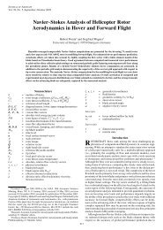
Figure 2A — Drive<br />
circuit for a typical<br />
close-spaced foursquare<br />
array with<br />
extended elements.<br />
2B — Simplifi ed<br />
drive circuit for 2a,<br />
as developed by the<br />
author.<br />
maximum current on each element are<br />
0.<strong>25</strong> λ from the top, which makes their<br />
effective spacing about 0.15 λ. If we drive<br />
this array as a conventional close-spaced<br />
four-square it requires relative currents<br />
of 1.3 A at 0°, two of 1 A at -120° and 1<br />
A at -240° for the rear, center and front<br />
elements, respectively. Because all these<br />
currents return to a common ground<br />
point, the Earth connection loss is only<br />
that due to their vector sum of 0.8 A at<br />
-230°. Consequently the ground system<br />
is less important from a loss standpoint<br />
than for a conventional four-square with<br />
individual ground returns. Conventional<br />
all-driven-element operation requires a<br />
feed system like that in Figure 2. Here L 1 /<br />
C 1 handle input matching for the feeder. L 2 /<br />
C 2 and L 3 /C 3 are dual-purpose networks<br />
that determine phase delay and voltage<br />
ratio.<br />
The 90° coaxial phasing lines are used<br />
to convert the voltages at their input ends<br />
into corresponding currents in the elements.<br />
In this case, because the elements<br />
are longer than 0.<strong>25</strong> λ, we also need to<br />
match them with series capacitors C 4 to C 7<br />
of equal value in order to keep the VSWR<br />
low on the phasing lines.<br />
We do not have to do it this way!<br />
Simplifying the Feed System<br />
If we don’t drive the front and rear<br />
elements, we have a parasitic array. By<br />
adjusting the matching capacitors in this<br />
confi guration, we can control the current<br />
amplitude and phase. In fact we can<br />
find values that will give the optimum<br />
amplitudes that we could have calculated<br />
for all-driven-element operation. Because<br />
this array is relatively close spaced the<br />
Figure 3 — Direction control and tuning<br />
circuit for the G3LNP four-square.<br />
18 November/December 2008 NCJ