pdf 6436KB Sep 25 2010 04
pdf 6436KB Sep 25 2010 04
pdf 6436KB Sep 25 2010 04
- TAGS
- 81.70.242.211

Create successful ePaper yourself
Turn your PDF publications into a flip-book with our unique Google optimized e-Paper software.
KØXG Systems<br />
Antenna<br />
Rotation<br />
and<br />
Control<br />
Systems<br />
Guyring<br />
bearings for<br />
rotating<br />
towers.<br />
Large ground mounted<br />
rotating bases for turning the<br />
whole tower.<br />
Large elevated rotors for<br />
rotating towers on towers.<br />
Accessories for mounting<br />
antennas to rotating towers.<br />
New rotor control system for<br />
tracking and aligning multi<br />
stacked antennas.<br />
Turn, align and track all your<br />
antennas with one Computer<br />
control system. Auto band<br />
selection from your radio.<br />
Visit Our Web Site!<br />
www.KØXG.com<br />
KØXG Systems<br />
1117 Highland Park Dr.<br />
Bettendorf, IA 52722<br />
(563) 355-7451<br />
kØxg@kØxg.com<br />
20 November/December 2008 NCJ<br />
capacitor to minimum and the refl ector<br />
and input capacitors to maximum. Apply<br />
low power and reduce the rear element<br />
(reflector) tuning capacitance for 1.3<br />
times the current or brightness as the<br />
driven element wire. Reverse the array<br />
and increase the front element (director)<br />
capacitance for the same current as in the<br />
driven element wire. If using lamps, you<br />
will need to experiment with a variable dc<br />
supply in order to know what 30 percent<br />
additional current looks like.<br />
Repeat these adjustments because<br />
they interact. Then adjust the input<br />
capacitor for minimum VSWR. You may<br />
be able to improve on these settings by<br />
a front-to-back test with the assistance<br />
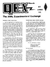
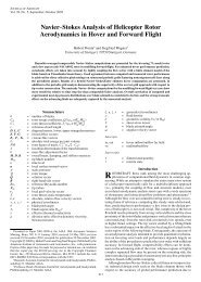
Figure 5 — Measured front-to-back directivity for the G3LNP array.<br />
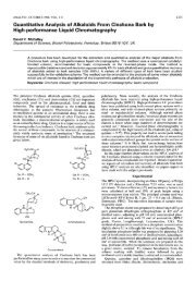
Figure 6 — An EZNEC plot of the<br />
vertical radiation pattern at 30°<br />
elevation with the antenna adjusted as<br />
a parasitic array on 3.79 MHz.<br />
of a local station, but it is unlikely that<br />
you will get any more gain. Figure 5<br />
shows measured F/B results for my<br />
80 meter array after such adjustments.<br />
Figure 6 shows a computer-generated<br />
vertical radiation pattern at 30° elevation<br />
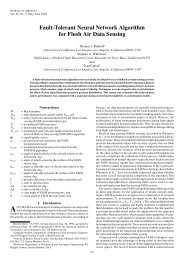
for the 80 meter array, while Figure 7<br />
shows the horizontal pattern.<br />
Notes<br />
1 Preedy,G3LNP. “Single-Support Directional<br />
Wires.” RadCom, Aug/<strong>Sep</strong> 1997.<br />
2 Devoldere, ON4UN. Low-Band DXing (4th ed),<br />
p 11-35, ARRL.<br />
Figure 7 — An EZNEC plot of the<br />
horizontal radiation pattern at 3.79 MHz.