LOC Cooling System For industrial use
LOC Cooling System For industrial use
LOC Cooling System For industrial use

Create successful ePaper yourself
Turn your PDF publications into a flip-book with our unique Google optimized e-Paper software.
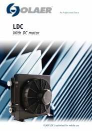
<strong>LOC</strong><br />
<strong>Cooling</strong> system<br />
The Professional Choice<br />
OLAER <strong>LOC</strong> | optimized for <strong>industrial</strong> <strong>use</strong>
Olaer is a global player specialising in innovative, effi cient system solutions for temperature optimisation and energy storage.<br />
All over the world, our products are working in the most diverse environments and applications.<br />
<strong>LOC</strong> <strong>Cooling</strong> <strong>System</strong><br />
The <strong>LOC</strong> cooling system with three-phase AC motor is<br />
optimized for <strong>use</strong> in the <strong>industrial</strong> sector. The system is<br />
supplied ready for installation. An integrated<br />
circulation pump makes it possible to cool and treat<br />
the oil in a separate circuit – offl ine cooling. The<br />
cooling system is also available with the FX3 fi lter unit.<br />
Together with a wide range of accessories, the <strong>LOC</strong><br />
cooling system is suitable for installation in most<br />
applications and environments. The maximum cooling<br />
capacity is 45 kW at ETD 40 °C. Choosing the right<br />
cooler requires precise system sizing. The most reliable<br />
way to size is with the aid of our calculation program. This<br />
program, together with precise evaluations from our<br />
experienced, skilled engineers, gives you the<br />
opportunity for more cooling per € invested.<br />
Overheating - an expensive problem<br />
An under-sized cooling capacity produces a temperature<br />
balance that is too high. The consequences are poor<br />
lubricating properties, internal leakage, a higher risk<br />
of cavitation, damaged components, etc. Overheating<br />
leads to a signifi cant drop in cost-effi ciency and<br />
environmental consideration.<br />
OLAER | <strong>LOC</strong><br />
<strong>For</strong> <strong>industrial</strong> <strong>use</strong> – maximum cooling capacity 45 kW<br />
<strong>Cooling</strong> capacity<br />
Lifetime<br />
Temperature optimisation - a basic prerequisite<br />
for cost-effi cient operation<br />
Temperature balance in a hydraulic system occurs when<br />
the cooler can cool down the energy input that the<br />
system does not consume - the system’s lost energy<br />
(Ploss = Pcool = Pin – P<strong>use</strong>d).<br />
Temperature optimisation means that temperature<br />
balance occurs at the system’s ideal working<br />
temperature – the temperature at which the oil’s<br />
viscosity and the air content comply with recommended<br />
values. The correct working temperature produces a<br />
number of economic and environmental benefi ts:<br />
Extended hydraulic system life.<br />
Extended oil life.<br />
Increased hydraulic system availability - more<br />
operating time and fewer shutdowns.<br />
Reduced service and repair costs.<br />
Maintained high effi ciency in continuous<br />
operation – the system effi ciency falls if the<br />
temperature exceeds the ideal working<br />
temperature.<br />
2 www.olaer.com
OLAER | <strong>LOC</strong><br />
Clever design and the right choice of<br />
materials and components produce a long<br />
<strong>use</strong>ful life, high availability and low service<br />
and maintenance costs.<br />
Cooler matrix<br />
with low pressure drop and<br />
high cooling capacity.<br />
Integrated<br />
ciculation pump<br />
produces and even fl ow with<br />
low pressure pulsations.<br />
Quiet<br />
fan and fan motor.<br />
Easy to maintain<br />
and easy to retrofi t in<br />
many applications.<br />
Compact design<br />
and low weight.<br />
The Professional Choice 3
Proprietary outer helical wrap<br />
Tightly bonds to each pleat for stability<br />
and strength.<br />
Benefi ts: Reliable, consistent performance<br />
and resistance to severe operating<br />
conditions.<br />
Good things come in small packages…<br />
Characteristics<br />
Media substrate support layer<br />
(not shown) Provides support for the<br />
media and aids in drainage fl ow.<br />
Benefi ts: Reliable, consistent performance.<br />
Coreless/cageless design<br />
Outer element cage is a permanent part of the<br />
fi lter housing.<br />
Benefi ts: Lighter, environmentally friendly<br />
element for reduced disposal costs and ease of<br />
element change-out.<br />
Stress-resistant design<br />
Uniform pore size control layer<br />
Tapered pore structure<br />
Epoxy resin bonded fi bre matrix with small fi bre size<br />
Anti-static design<br />
cSt cSt<br />
450<br />
300<br />
150<br />
0<br />
Filter material LP<br />
<strong>For</strong> systems with working pressure<br />
below 200 bar.<br />
30 50 70<br />
300<br />
200<br />
100<br />
Up and downstream mesh layers<br />
Proprietary cushion layer<br />
Provides support for the media and<br />
protection from handling.<br />
Benefi ts: Reliable, consistent performance.<br />
Create fl ow channels for uniform fl ow<br />
through the fi lter.<br />
Benefi ts: Extended element life for lower<br />
operating costs.<br />
4” LP 4” HP<br />
Flow<br />
l/min.<br />
0<br />
Benefi ts<br />
Filter material HP<br />
<strong>For</strong> systems with working pressure<br />
above 200 bar.<br />
30 50 70<br />
Material<br />
Inert, inorganic fi bres securely bonded in a<br />
fi xed, tapered pore structure with increase<br />
resistance to system stresses such as cyclic<br />
fl ow and dirt loading.<br />
Benefi ts: Improved performance over the fi lter<br />
life and more consistent fl uid cleanliness.<br />
OLAER | <strong>LOC</strong><br />
Ease of element change-out<br />
Enhanced performance under cyclic fl ow and pressure conditions<br />
Maintained effi ciency during the entire life<br />
Dirt captured throughout the media depth<br />
High particles removal effi ciency<br />
Minimized static charge generation and electrostatic discharge<br />
Choose the right fi lter element:<br />
Corrosion-resistant end caps feature exclusive<br />
Auto-Pull tabs for automatic element<br />
extraction upon opening the housing.<br />
Benefi ts: Ease of element change-out.<br />
O-ring seal<br />
Prevents contaminant bypassing the fi ltration<br />
medium under normal operation.<br />
Benefi ts: Reliable, consistent performance.<br />
1. Filter material HP or LP – depends on pressure level,<br />
i.e. the system’s average pressure.<br />
2. The fi lter’s fl ow capacity – the oil fl ow is<br />
determined by the <strong>LOC</strong> cooler model, i.e.<br />
3.<br />
current cooling requirement.<br />
The length of the fi lter element – depends on the<br />
operating viscosity. The pressure drop over the fi lter<br />
element is proportional to the viscosity, e.g. oil that<br />
is three times as thick produces a pressure drop that<br />
is three times as high.<br />
4 www.olaer.com<br />
Flow<br />
l/min.
OLAER | <strong>LOC</strong><br />
The FX3 original fi lter gives you constantly cleaner oil, more lasting system protection and greater stability during operation at varying fl ow and pressure.<br />
The FX3 captures dirt along the whole length of the fi lter material and retains effi ciency throughout its <strong>use</strong>ful life.<br />
The element is easy to replace, it comes out when you unscrew the cover - it couldn’t be simpler.<br />
Why not clean the oil while cooling it? Equipped with<br />
our fi lter unit FX3 the oil will be cleaned in a separate<br />
circuit, an ideal complement to the system fi lter. Our<br />
fi lter unit FX3 is available as option.<br />
Filter technique<br />
FX3 Original Filter<br />
Designing fi lter media has traditionally been a<br />
question of balance. By making the medium fi ner, more<br />
effi cient and cleaner, pressure drop and/or<br />
servicable life is sacrifi ced. To get low clean pressure<br />
FX3<br />
FILTER UNI T<br />
Compact<br />
Environment friendly<br />
Highly effi cient<br />
element makes difference<br />
drop the removal effi ciency is sacrifi ced. With FX3<br />
fi lter media OLAER has improved the fi lter’s ability<br />
to maintain fl uid cleanliness, while at the same time<br />
increasing fl ow capacity (reducing pressure drop).<br />
The result is a better and more consistent system<br />
protection, i.e. high fl ow capacity in a small envelope<br />
size, optimum performance at stages of fi lter life, i.e.<br />
optimum performance under cyclic fl ow and pressure<br />
conditions for consistently cleaner fl uid.<br />
The Professional Choice 5
Calculate the cooling capacity requirement<br />
<strong>Cooling</strong><br />
capacity<br />
requirement?<br />
Installed<br />
capacity<br />
Theoretical<br />
capacity losses<br />
Flow?<br />
Pressure?<br />
Pump capacity?<br />
Enter your values ....<br />
Measure in<br />
your existing<br />
unit<br />
Choose the right kind of cooler<br />
... suggested solution<br />
Contact<br />
our<br />
engineers<br />
OLAER | <strong>LOC</strong><br />
6 www.olaer.com
OLAER | <strong>LOC</strong><br />
Better energy consumption means not only less environmental impact, but also reduces operating costs, i.e. more cooling per € invested.<br />
More cooling per €<br />
with precise calculations and our engineers’ support<br />
Optimal sizing produces effi cient cooling. Correct sizing ng<br />
requires knowledge and experience. Our calculation on<br />
program, combined with our engineers’ support, gives es<br />
you access to this very knowledge and experience. The he<br />
result is more cooling per € invested.<br />
The <strong>use</strong>r-friendly calculation program can be<br />
downloaded from – www.olaer.se<br />
Valuable system review into the bargain<br />
A more wide-ranging review of the hydraulic system is<br />
often a natural element of cooling calculations. Other er<br />
potential system improvements can then be discussed ed<br />
– e.g. fi ltering, offl ine or online cooling, etc. Contact us<br />
for further guidance and information.<br />
OLAER’s quality and performance guarantee ee<br />
insurance for your operations and systems<br />
A constant striving towards<br />
more cost-effi cient and environ-<br />
men ment friendly hydraulic systems<br />
requ requires continuous development.<br />
me Areas where we are<br />
continuously co<br />
seeking to<br />
improve im performance include<br />
cooling c capacity, noise level,<br />
pressure drop and fatigue.<br />
Meticulous quality and performance tests are conducted<br />
in our laboratory. All tests and measurements take<br />
place in accordance with standardised methods -<br />
cooling capacity in accordance with EN1048, noise<br />
level ISO 3743, pressure drop EN 1048 and fatigue ISO<br />
10771-1.<br />
<strong>For</strong> more information about our standardised tests, ask<br />
for “OLAER’s blue book – a manual for more reliable<br />
cooler purchasing”.<br />
The Professional Choice 7
Technical specifi cation<br />
<strong>LOC</strong> is designed primarily for synthetic oils, vegetable<br />
oils and mineral oil type HL/HLP in accordance with<br />
DIN 51524. Maximum oil temperature 100 °C.<br />
Maximum negative pressure in the inlet line is 0.4 bar<br />
with an oil-fi lled pump. Maximum pressure on the<br />
pump’s suction side is 0.5 bar.<br />
Maximum working pressure for the pump is 10 bar.<br />
<strong>For</strong> information about suction height, pressure, etc.<br />
see the QPM3 pump manual.<br />
Heat transfer tolerance ± 6 %<br />
3-PHASE MOTOR<br />
3-phase asynchronous motors in accordance with IEC 60034-1<br />
Nominal voltage *<br />
Insulation class F<br />
Rise of temperature B<br />
Protection class IP 55<br />
Recommended ambient temperature -20 °C - +40 °C<br />
* = See separate instructions for electric motor.<br />
TYPE Nom. oil fl ow<br />
l/min<br />
<strong>Cooling</strong> capacity<br />
in kW at EDT 40 °C<br />
<strong>Cooling</strong> capacity<br />
kW/°C<br />
Acoustic pressure level<br />
LpA dB(A) 1m*<br />
No. of poles/ Capacity<br />
kW<br />
OLAER | <strong>LOC</strong><br />
MATERIAL<br />
Pump housing/Cooler matrix Aluminum<br />
Fan blades/hub Glass fi bre reinforced polypropylene/<br />
Aluminum<br />
Fan housing Steel<br />
Fan guard Steel<br />
Other parts Steel<br />
Surface treatment Electrostatically powder-coated<br />
FX3 FILTER UNIT (option) Aluminum<br />
The fi lter housing has a built-in bypass valve, pre-set<br />
pressure 4.5 ± 0.3 bar.<br />
CONTACT OLAER FOR ADVICE ON<br />
Oil temperatures > 100 °C<br />
Oil viscosity > 100 cSt<br />
Aggressive environments<br />
Ambient air rich in particles<br />
High-altitude locations<br />
Weight<br />
kg (approx)<br />
<strong>LOC</strong> 004 - 4 - D - A 20 2.7 0.07 57 4-0.75 23<br />
<strong>LOC</strong>2 007 - 4 - D - A 20 5.6 0.14 64 4-0.75 30<br />
<strong>LOC</strong>2 007 - 4 - D - B 40 7.2 0.18 64 4-.075 30<br />
<strong>LOC</strong>2 007 - 4 - D - C 60 8.0 0.20 65 4-1.50 36<br />
<strong>LOC</strong>2 007 - 4 - D - D 80 8.4 0.21 65 4-1.50 36<br />
<strong>LOC</strong>2 011 - 4 - D - A 20 9.2 0.23 70 4-0.75 34<br />
<strong>LOC</strong>2 011 - 4 - D - B 40 10.4 0.26 70 4-0.75 34<br />
<strong>LOC</strong>2 011 - 6 - D - C 40 7.6 0.19 61 6-1.10 40<br />
<strong>LOC</strong>2 011 - 6 - D - D 55 8.8 0.22 61 6-1.10 40<br />
<strong>LOC</strong>2 011 - 4 - D - C 60 12.0 0.30 70 4-1.50 40<br />
<strong>LOC</strong>2 011 - 4 - D - D 80 13.2 0.33 70 4-1.50 40<br />
<strong>LOC</strong>2 016 - 4 - D - A 20 11.2 0.28 74 4-1.50 45<br />
<strong>LOC</strong>2 016 - 4 - D - B 40 15.6 0.39 74 4-1.50 45<br />
<strong>LOC</strong>2 016 - 6 - D - C 40 12.4 0.31 64 6-1.10 45<br />
<strong>LOC</strong>2 016 - 6 - D - D 55 14.0 0.35 64 6-1.10 45<br />
<strong>LOC</strong>2 016 - 4 - D - C 60 18.0 0.45 74 4-1.50 45<br />
<strong>LOC</strong>2 016 - 4 - D - D 80 19.6 0.49 74 4-1.50 45<br />
<strong>LOC</strong>2 023 - 4 - D - B 40 21.2 0.53 77 4-1.50 53<br />
<strong>LOC</strong>2 023 - 6 - D - C 40 16.8 0.42 67 6-1.10 53<br />
<strong>LOC</strong>2 023 - 6 - D - D 55 18.4 0.46 67 6-1.50 53<br />
<strong>LOC</strong>2 023 - 4 - D - C 60 24.4 0.61 77 4-2.20 62<br />
<strong>LOC</strong>2 023 - 4 - D - D 80 26.8 0.67 77 4-2.20 62<br />
<strong>LOC</strong> 033 - 6 - A - D 55 26.0 0.65 74 6-2.20 92<br />
<strong>LOC</strong> 033 - 4 - A - C 60 32.0 0.80 85 4-3.00 76<br />
<strong>LOC</strong> 033 - 4 - A - D 80 34.8 0.87 85 4-3.00 76<br />
<strong>LOC</strong> 044 - 6 - A - D 55 34.0 0.85 77 6-2.20 98<br />
<strong>LOC</strong> 044 - 4 - A - C 60 40.0 1.00 86 4-3.00 85<br />
<strong>LOC</strong> 044 - 4 - A - D 80 44.8 1.12 86 4-3.00 85<br />
* = Electric motors specifi ed are calculated for max. working pressure 6 bar at 125 cSt and 50 Hz, 4 bar at 125 cSt and 60 Hz.<br />
If you require higher pressure, please contact us for a choice of motors with a higher output.<br />
** = Noise level tolerance ± 3 dB(A).<br />
8 www.olaer.com
OLAER | <strong>LOC</strong><br />
TYPE<br />
A B C D E F G H I J K L Mø<br />
<strong>LOC</strong> 004 - 4 - D - A 267 134 135 284 73 G1 420 90 164 163 488 58 9<br />
<strong>LOC</strong>2 007 - 4 - D - A 365 203 105 395 42 G1 510 160 215 225 558 50 9<br />
<strong>LOC</strong>2 007 - 4 - D - B 365 203 105 395 42 G1 510 160 215 225 571 50 9<br />
<strong>LOC</strong>2 007 - 4 - D - C 365 203 105 395 42 G1 510 160 215 225 620 50 9<br />
<strong>LOC</strong>2 007 - 4 - D - D 365 203 105 395 42 G1 510 160 215 225 633 50 9<br />
<strong>LOC</strong>2 011 - 4 - D - A 440 203 103 470 41 G1 510 230 252 249 582 50 9<br />
<strong>LOC</strong>2 011 - 4 - D - B 440 203 103 470 41 G1 510 230 252 249 595 50 9<br />
<strong>LOC</strong>2 011 - 6 - D - C 440 203 103 470 41 G1 510 230 252 249 643 50 9<br />
<strong>LOC</strong>2 011 - 6 - D - D 440 203 103 470 41 G1 510 230 252 249 657 50 9<br />
<strong>LOC</strong>2 011 - 4 - D - C 440 203 103 470 41 G1 510 230 252 249 644 50 9<br />
<strong>LOC</strong>2 011 - 4 - D - D 440 203 103 470 41 G1 510 230 252 249 657 50 9<br />
<strong>LOC</strong>2 016 - 4 - D - A 496 203 107 526 46 G1 510 230 285 272 640 50 9<br />
<strong>LOC</strong>2 016 - 4 - D - B 496 203 107 526 46 G1 510 230 285 272 653 50 9<br />
<strong>LOC</strong>2 016 - 6 - D - C 496 203 107 526 46 G1 510 230 285 272 665 50 9<br />
<strong>LOC</strong>2 016 - 6 - D - D 496 203 107 526 46 G1 510 230 285 272 678 50 9<br />
<strong>LOC</strong>2 016 - 4 - D - C 496 203 107 526 46 G1 510 230 285 272 665 50 9<br />
<strong>LOC</strong>2 016 - 4 - D - D 496 203 107 526 46 G1 510 230 285 272 678 50 9<br />
<strong>LOC</strong>2 023 - 4 - D - B 580 356 104 610 40 G1 610 305 322 287 668 50 14<br />
<strong>LOC</strong>2 023 - 6 - D - C 580 356 104 610 40 G1 610 305 322 287 722 50 14<br />
<strong>LOC</strong>2 023 - 6 - D - D 580 356 104 610 40 G1 610 305 322 287 722 50 14<br />
<strong>LOC</strong>2 023 - 4 - D - C 580 356 104 610 40 G1 610 305 322 287 709 50 14<br />
<strong>LOC</strong>2 023 - 4 - D - D 580 356 104 610 40 G1 610 305 322 287 722 50 14<br />
<strong>LOC</strong> 033 - 6 - A - D 692 356 99 722 32 G1¼ 610 406 378 318 754 70 14<br />
<strong>LOC</strong> 033 - 4 - A - C 692 356 99 722 32 G1¼ 610 406 378 318 727 70 14<br />
<strong>LOC</strong> 033 - 4 - A - D 692 356 99 722 32 G1¼ 610 406 378 318 741 70 14<br />
<strong>LOC</strong> 044 - 6 - A - D 692 356 99 866 49 G1¼ 610 584 450 343 779 70 14<br />
<strong>LOC</strong> 044 - 4 - A - C 692 356 99 866 49 G1¼ 610 584 450 343 750 70 14<br />
<strong>LOC</strong> 044 - 4 - A - D 692 356 99 866 49 G1¼ 610 584 450 343 762 70 14<br />
The Professional Choice 9
Key for <strong>LOC</strong> and <strong>LOC</strong>2<br />
cooling systems<br />
All positions must be fi lled in when ordering<br />
EXAMPLE:<br />
<strong>LOC</strong>2 - 011 - 6 - A - C - L - 50 - S20 - D - E0 - 0<br />
1 2 3 4 5 6 7 8 9 10/11 12<br />
1. TYPE OF COOLING SYSTEM = L0C / <strong>LOC</strong>2<br />
2. COOLER SIZE<br />
004, 007, 011, 016, 023, 033, 044<br />
3. NUMBER OF POLES, MOTOR<br />
4 - pole = 4<br />
6 - pole = 6<br />
4. VOLTAGE AND FREQUENCY<br />
Three-phase 220-240/380-420 V 50 Hz* = A<br />
Three-phase 440-480 V 60 Hz* = B<br />
Three-phase 220-240/380-420 V 50 Hz 440/480 V 60 Hz** = D<br />
Three-phase 500 V 50 Hz = E<br />
Three-phase 400/690 V 50 Hz 440-480 V 60 Hz = F<br />
Three-phase 525 V 50 Hz = G<br />
Motor for special voltage (stated in plain language) = X<br />
* = for <strong>LOC</strong> 033 to <strong>LOC</strong> 044<br />
** = for <strong>LOC</strong> 004 to <strong>LOC</strong>2 023<br />
5. PUMP SIZE<br />
Displacement 15 cm 3 /r = A<br />
Displacement 30 cm 3 /r = B<br />
Displacement 45 cm 3 /r = C<br />
Displacement 60 cm 3 /r = D<br />
Special = X<br />
6. BYPASS VALVE, PUMP<br />
No bypass valve = O<br />
Built-in bypass valve, 5 bar internal = L<br />
Built-in bypass valve, 10 bar internal = H<br />
Built-in bypass valve, 5 bar external = K<br />
Built-in bypass valve, 10 bar external = M<br />
7. THERMO CONTACT<br />
<strong>For</strong> temperature alarm, not for direct control of electric motor.<br />
No thermo contact = 00<br />
40 °C = 40<br />
50 °C = 50<br />
60 °C = 60<br />
70 °C = 70<br />
80 °C = 80<br />
90 °C = 90<br />
8. COOLER MATRIX<br />
Standard = 000<br />
Two-pass = T00<br />
Built-in, pressure-controlled bypass, single-pass<br />
2 bar = S20<br />
5 bar = S50<br />
8 bar = S80<br />
Built-in, pressure-controlled bypass, two-pass*<br />
2 bar = T20<br />
5 bar = T50<br />
8 bar = T80<br />
OLAER | <strong>LOC</strong><br />
Built-in temperature and pressure-controlled bypass, single-pass<br />
50 °C, 2.2 bar = S25<br />
60 °C, 2.2 bar = S26<br />
70 °C, 2.2 bar = S27<br />
90 °C, 2.2 bar = S29<br />
Built-in temperature and pressure-controlled bypass, two-pass*<br />
50 °C, 2.2 bar = T25<br />
60 °C, 2.2 bar = T26<br />
70 °C, 2.2 bar = T27<br />
90 °C, 2.2 bar<br />
* = not valid for <strong>LOC</strong> 004<br />
= T29<br />
9. MATRIX GUARD<br />
No guard = 0<br />
Stone guard = S<br />
Dust guard = D<br />
Dust and stone guard = P<br />
10. FX3 FILTER UNIT (sizing, see page 4)<br />
No fi lter unit = 0<br />
Filter unit with 4” element HP = A<br />
Filter unit with 4” element LP = B<br />
Filter unit with 8” element HP = E<br />
Filter unit with 8” element LP = F<br />
11. PRESSURE DROP INDICATOR<br />
No pressure drop indicator. = O<br />
Visual pressure drop indicator with manual reset. = D<br />
Visual pressure drop indicator with thermo<br />
guard and manual reset. No signal below 0 °C,<br />
signal above +29 °C. = P<br />
Electric pressure drop indicator with automatic reset.<br />
Connection in accordance with DIN 43650<br />
ISO 4400 (Hirschmann) IP 65. = M<br />
Electric pressure drop indicator<br />
with 2-pole AMP contact. = U<br />
12. STANDARD/SPECIAL<br />
Standard = O<br />
Special = Z<br />
SPARE PARTS<br />
Part number Description<br />
58920102 Filter element 04” HP<br />
58920103 Filter element 04” LP<br />
58920302 Filter element 08” HP<br />
58920303 Filter element 08” LP<br />
589310 O-ring for fi lter housing cover<br />
The information in this brochure is subject to change without prior notice.<br />
10 www.olaer.com
OLAER | <strong>LOC</strong><br />
With our specialist expertise, industry knowledge and advanced technology,<br />
we can offer a range of different solutions for coolers and accessories to meet your requirements.<br />
Take the next step<br />
- choose the right accessories<br />
Supplementing a hydraulic system with a cooler, cooler accessories and an accumulator gives you increased availability<br />
and a longer <strong>use</strong>ful life, as well as lower service and repair costs. All applications and operating environments are unique.<br />
A well-planned choice of the following accessories can thus further improve your hydraulic system. Please contact<br />
Olaer for guidance and information.<br />
Pressure-controlled<br />
bypass valve Integrated<br />
Allows the oil to bypass the cooler matrix if the<br />
pressure drop is too high. Reduces the risk of<br />
the cooler bursting, e.g. in connection with<br />
cold starts and temporary peaks in pressure<br />
or fl ow. Available for single-pass or two-pass<br />
matrix design.<br />
Temperature-controlled<br />
bypass valve Integrated<br />
Same function as the pressure-controlled<br />
by–pass valve, but with a temperature-controlled<br />
opening pressure - the hotter the oil, the<br />
higher the opening pressure. Available for<br />
single-pass or two-pass matrix design.<br />
Thermo contact<br />
Sensor with fi xed set point. <strong>For</strong> temperature<br />
warnings, and for more cost-effi cient operation<br />
and better environmental consideration through<br />
the automatic switching on and off of the<br />
fan motor.<br />
Stone guard/Dust guard<br />
Protects components and systems from<br />
tough conditions.<br />
Lifting eyes<br />
<strong>For</strong> simple installation and relocation.<br />
Temperature-controlled<br />
3-way valve External<br />
Same function as the temperature-controlled<br />
bypass valve, but positioned externally.<br />
Note: must be ordered separately.<br />
The Professional Choice 11
Global perspective<br />
Olaer is a global player specialising in innovative,<br />
efficient system solutions for temperature optimisation<br />
and energy storage. Olaer develops, manufactures and<br />
markets products and systems for a number of different<br />
sectors, e.g. the aircraft, engineering, steel and<br />
mining industries, as well as for sectors such as oil and<br />
gas, contracting and transport, farming and forestry,<br />
renewable energy, etc.<br />
All over the world, our products operate in the most<br />
diverse environments and applications. One constantly<br />
and local entrepreneurial flair<br />
www.olaer.com<br />
The Professional Choice<br />
- in Fluid Energy Management<br />
repeated demand in the market is for optimal energy<br />
storage and temperature optimisation. We work at a<br />
local level with a whole world as our workplace – local<br />
entrepreneurial flair and a global perspective go hand<br />
in hand.<br />
Our local presence, long experience and a wealth of<br />
knowledge combine with our cutting-edge expertise<br />
to give you the best possible conditions for making a<br />
professional choice.<br />
Copyright © 2010 OLAER