A Bio-inspired Collision Avoidance System ... - university press
A Bio-inspired Collision Avoidance System ... - university press
A Bio-inspired Collision Avoidance System ... - university press

Create successful ePaper yourself
Turn your PDF publications into a flip-book with our unique Google optimized e-Paper software.
Abstract— Nature offers a great source of inspiration to create<br />
robust systems that can assist humans to achieve different tasks.<br />
Neuromorphic engineering is an emerging field and when it comes to<br />
create a device that could assist a blind or a visually impaired human<br />
and also replace the traditional tools like white canes or guiding<br />
dogs, this can be really challenging. Even if insects are considered<br />
inferior species in comparation with vertebrates, they poses a visual<br />
system that colud be used in such an applications. An important<br />
condition for a person to move freely in an enviroment is to be able<br />
to detect any obstacle which may interfere with the trajectory of<br />
motion in order to avoid a possible collision with that obstacle. This<br />
article presents a possible implementation of a collision avoidance<br />
system <strong>inspired</strong> from the insects visual system with some specific<br />
modifications, in order to be useful for human applications in an real<br />
enviroment.<br />
Keywords— bio-<strong>inspired</strong>, insects, vision, collision detection,<br />
obstacle avoidance, EMD, Reichardt correlator<br />
D<br />
INTERNATIONAL JOURNAL OF SYSTEMS APPLICATIONS, ENGINEERING & DEVELOPMENT<br />
Issue 6, Volume 5, 2011<br />
A <strong>Bio</strong>-<strong>inspired</strong> <strong>Collision</strong> <strong>Avoidance</strong> <strong>System</strong><br />
Concept for People with Visual Disabilities<br />
MIHAI-EMANUEL BASCH, RÓBERT ISTVÁN LŐRINCZ, DAVID GEORGE CRISTEA,<br />
VIRGIL TIPONUT, IVAN BOGDANOV<br />
I. BIOLOGICAL BACKGROUND<br />
URING the evolution period, insects have developed into<br />
more than one million species and they are found in<br />
almost all environments of the planet.<br />
Studying insect vision is very important due to the fact that are<br />
more simple that another species, but complex enough to be a<br />
source of inspiration in creating robust visual system.<br />
The fly eyes are constructed from multiple elements called<br />
ommatidia or facetes. Each facet contains its own lens and its<br />
own set of photoreceptors [10]. The different photoreceptors<br />
in one ommatidium have different optical axes, but there are<br />
groups of photoreceptors within neighboring ommatidia which<br />
have<br />
This work was partially supported by the strategic grant<br />
POSDRU/88/1.5/S/50783, Project ID50783 (2009), co-financed by the<br />
European Social Fund – Investing in People, within the Sectoral Operational<br />
Programme Human Resources Development 2007-2013.<br />
This work was partially supported by the strategic grant POSDRU<br />
6/1.5/S/13, Project ID6998 (2008), co-financed by the European Social Fund<br />
– Investing in People, within the Sectoral Operational Programme Human<br />
Resources Development 2007-2013.<br />
MIHAI-EMANUEL BASCH is with the Politehnica University Timisoara,<br />
Romania (phone: +40762569889; e-mail: bash_mihai@yahoo.com).<br />
RÓBERT ISTVÁN LŐRINCZ, with the Politehnica University Timisoara,<br />
Romania (phone:+40741181074; e-mail: lorinczroby@yahoo.com).<br />
DAVID GEORGE CRISTEA is with the Politehnica University Timisoara,<br />
Romania (phone:+40762557036; e-mail: cristea.david@yahoo.com).<br />
VIRGIL TIPONUT is with the Politehnica University Timisoara, Romania<br />
(phone: +40256403337; e-mail: virgil.tiponut@etc.upt.ro).<br />
IVAN BOGDANOV is with the Politehnica University Timisoara,<br />
Romania (phone: +40256403338; e-mail: ivan.bogdanov@etc.upt.ro).<br />
701<br />
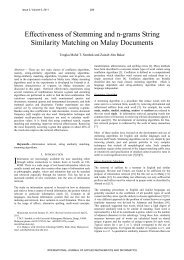
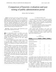
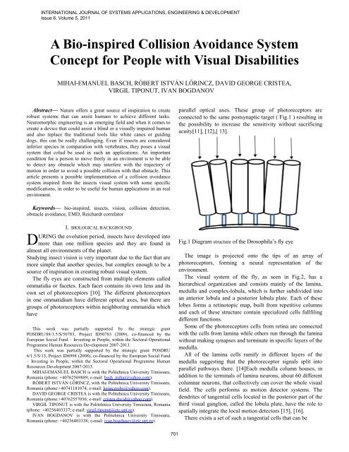
parallel optical axes. These group of photoreceptors are<br />
connected to the same postsynaptic target ( Fig.1 ) resulting in<br />
the possibility to increase the sensitivity without sacrificing<br />
acuity[11], [12],[ 13].<br />
Fig.1 Diagram structure of the Drosophila’s fly eye<br />
The image is projected onto the tips of an array of<br />
photoreceptors, forming a neural representation of the<br />
environment.<br />
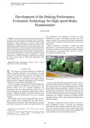
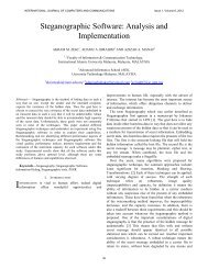
The visual system of the fly, as seen in Fig.2, has a<br />
hierarchical organization and consists mainly of the lamina,<br />
medulla and complex-lobula, which is further subdivided into<br />
an anterior lobula and a posterior lobula plate. Each of these<br />
lobes forms a retinotopic map, built from repetitive columns<br />
and each of these structure contain specialized cells fullfiling<br />
different functions.<br />
Some of the photoreceptors cells from retina are connected<br />
with the cells from lamina while others run through the lamina<br />
without making synapses and terminate in specific layers of the<br />
medulla.<br />
All of the lamina cells ramify in different layers of the<br />
medulla suggesting that the photoreceptor signals split into<br />
parallel pathways there. [14]Each medulla column houses, in<br />
addition to the terminals of lamina neurons, about 60 different<br />
columnar neurons, that collectively can cover the whole visual<br />
field. The cells performs as motion detector systems. The<br />
dendrites of tangential cells located in the posterior part of the<br />
third visual ganglion, called the lobula plate, have the role to<br />
spatially integrate the local motion detectors [15], [16].<br />
There exists a set of such a tangential cells that can be
INTERNATIONAL JOURNAL OF SYSTEMS APPLICATIONS, ENGINEERING & DEVELOPMENT<br />
Issue 6, Volume 5, 2011<br />
Fig.2 Anatomical structure of the the Drosophila’s visual system<br />
grouped according to their preferred direction of image<br />
motion, some of the cells respond preferentially to horizontal<br />
image motion from front to back (the HS-cells), others to<br />
horizontal image motion in the opposite direction, others<br />
respond selectively to vertical image motion from top to<br />
bottom (the VS cells) [17].<br />
The connections between the tangential neurons of the left<br />
and the right lobula plate as well as between neurons within<br />
one lobula plate tune many tangential cells responsive to<br />
specific motion signals in front of both eyes, and others that<br />
are selectively responsive to motion of small moving objects<br />
or relative motion [18], [19].<br />
Tangential cells have been shown to synapse onto<br />
descending neurons which connect either to the flight motor in<br />
the thoracic ganglion of the animals controlling the various<br />
flight maneuvers, or to specific neck muscles controlling head<br />
movements[20], [21].<br />
When an animal moves in an environment or is moving his<br />
eyes or an object is moving in front of the eyes, the visual<br />
system is faced with motion perception [22], [23]. Even so,<br />
this movement is not represented in two-dimensional pattern<br />
on the retina of enlightenment but is processed in time of<br />
lighting the image crossing the retina. This is one of the first<br />
and most basics step performed by the visual system. This<br />
primary motion detection is a key to neural processing and this<br />
702<br />
algorithm, although not yet understood at the cellular level is<br />
supposed to be at any species. In literature, the development of<br />
models for motion detection has been experienced in particular<br />
by investigations on two systems: rabbit retina and insects.<br />
Insects process visual motion information in a local<br />
hierarchy. Although the compound eye has a construction with<br />
multiples lens, the pattern projected on the retina which is<br />
under the lens is a single image of the visual scene [24].<br />
Photoreceptors in the retina adapts to the ambient light,<br />
signaling deviations from this level. These signals are<br />
transferred to the next level of cells, lamina (Fig.2). These<br />
cells have a character of a time-pass response, with emphasis<br />
on temporal changes. The next level is in the medulla<br />
processing, a layer of cells that are very difficult to study<br />
because of their small size. However, indirect evidence<br />
suggests that there is local motion processing (of adjacent<br />
photoreceptors). These estimates of motion are integrated into<br />
the tangential cells of the lobula. The domestic fly has 50-60<br />
such cells present in each half of the brain. These are the beststudied<br />
cells in the fly visual system, best known of their<br />
properties [25], [26]. Cells in the lobula generally respond to<br />
the movement of large parts of the visual field. Some of these<br />
cells appear to be adapted filters for optic flow patterns<br />
produced by rotation or translation on some particular axes.<br />
Some of these cells are most likely compensating the control to<br />
prevent rotation motor reflexes during flight. Others are<br />
sensitive only to small objects that move in the field of vision.
INTERNATIONAL JOURNAL OF SYSTEMS APPLICATIONS, ENGINEERING & DEVELOPMENT<br />
Issue 6, Volume 5, 2011<br />
It is assumed that this type of cells allows the fly to locate<br />
nearby objects. All these sensory abilities require the<br />
movement is initially detected locally between each pair of<br />
photoreceptors [27], [28].<br />
The locust visual system structure has many similarities but<br />
the interest comes in the identified two neurons, the DCMD<br />
neuron, known as descending contralateral movement detector,<br />
localized in the postsynaptic area, and the LGMD neuron<br />
known as lobula giant movement detector respond selectively<br />
to the images of an object approaching towards its eye [9].<br />
LGMD neuron is excited by the related elements that are<br />
arranged in the retina. Excitation is given as a pulse or a<br />
potential. Number of related elements excited depends on the<br />
angle of the object defined by eye, so when an object is<br />
approaching the neuron excitation increases very rapidly, as<br />
they approach. Objects that are not on collision course do not<br />
show the same increase in excitation and thus is unlikely to<br />
trigger avoidance reactions.<br />
The principle of operation of the neuron is relatively simple.<br />
For collision detection method can also be used a method<br />
which calculate the increase in size of the object to determine<br />
if this is the direction of collision, but such a method requires<br />
the detection and the recognition of the object’s shape that is<br />
approaching. Such tasks are very expensive in terms of<br />
processing and even using the latest and fastest computers<br />
would run very slowly.<br />
LGMD neuron provides several methods to eliminate<br />
responses from objects that come near, methods that are<br />
simple both in terms of cognitive and computing. The most<br />
studied are lateral inhibition between pre-synapses involved<br />
and the "feed forward" post-synaptic inhibition of the LGMD<br />
neuron.<br />
The reaction of the neurons is more intense when the object<br />
is approaching on a collision course. In this case appears a<br />
race between excitation caused by edges moving over<br />
successive photoreceptors and inhibition spreading laterally.<br />
Experiments showed that the more edges contain the object the<br />
more intense is the response of the neurons [5], [8].<br />
II. ELEMENTARY MOTION DETECTOR<br />
Moving in a real environment of a person suffering from<br />
visual disability is conditioned primarily by the ability to<br />
detect obstacles that appear on walking path.<br />
Making an assistive device <strong>inspired</strong> by the visual system of<br />
insects is justified by the fact that insects although considered<br />
inferior beings, possess a neural structure and a visual system<br />
that allows them to perform important task such as landing,<br />
secure takeoff, visual navigation with obstacle avoidance and<br />
flight stabilization.<br />
In the last few years, the most studied insects related to the<br />
visual system were the locust and the fly. These studies<br />
showed that motion processing in insects is mainly based on an<br />
Elementary Motion Detector (EMD). This Elementary Motion<br />
Detector also known as Hassenstein-Reichardt detector is<br />
703<br />
supported by the behavioural and physiological model, which<br />
was revealed from the investigations on cells in the optic lobe<br />
of the insects and is considered that their role is to correlate<br />
the information from the photoreceptors in the retina, in order<br />
to encode the motion information.<br />
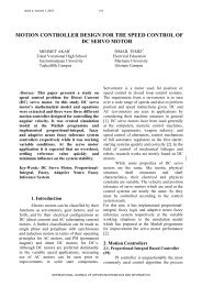
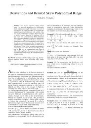
Fig.3 Functional block diagram for the Elementary Motion Detector<br />
and the related signals for each block<br />
The EMD structure is showed in Fig.3 and is basically<br />
formed from two channels where the signal received from the<br />
photoreceptors is delayed in each channel and multiplied with<br />
the non-delayed signal from the opposite channel, then are
subtracted in order to receive the motion information [1]-[3].<br />
If the result has a positive value means that an object has<br />
passed in front of the sensors from left to right and if the result<br />
has a negative value then the object has passed from right to<br />
left.<br />
If we consider the pattern of input a sinusoidal signal with<br />
wavelength λ moving with speed v [º / s]. Image intensity I (x,<br />
t) can be written as:<br />
( , ) = +Δ (2 ( + )) (1)<br />
where I is average intensity and spatial frequency fs. The<br />
contrast pattern is and ΔI/I. In each photoreceptor, this moving<br />
pattern produces a sinusoidal signal temporal with the<br />
frequency ft = vfs. Thus we can rewrite (1) as:<br />
( , ) = +Δ ( + )) (2)<br />
where ωt = 2πft and ωs = 2πfs. If two receivers have a<br />
separation angle of Φ, the signals measured by the two<br />
photoreceptors can be ex<strong>press</strong>ed as:<br />
1=| ( )| Δ ( − /2) (3)<br />
2=| ( )| Δ ( − /2) (4)<br />
where we have introduced H (ωt) as the frequency response of<br />
the photoreceptors. If using low-pass filters of first order, we<br />
get signals:<br />
I1( ) = | ( )| Δ ( 2 2 +1) -0.5 ( − /2<br />
− −1 ) (5)<br />
I2( ) = | ( )| Δ ( 2 2 +1) -0.5 ( − /2<br />
− −1 ) (6)<br />
Correlation is performed by multiplying the out of phase<br />
signals with adjacent non-delayed signals. The results are :<br />
1( ) = [ ( + ) − (2 − )] (7)<br />
2( ) = [ ( + ) − (2 − )] (8)<br />
where G and P are:<br />
= (| ( )| Δ ) 2 (2( 2 2 +1)) -0.5<br />
=<br />
INTERNATIONAL JOURNAL OF SYSTEMS APPLICATIONS, ENGINEERING & DEVELOPMENT<br />
Issue 6, Volume 5, 2011<br />
−1 ( )<br />
So, the final answer becomes:<br />
( ) = (Δ ) 2 | ( t)| 2 ( 2 2 +1) -0.5<br />
( ) (9)<br />
704<br />
III. BIO-INSPIRED COLLISION AVOIDANCE SYSTEM<br />
CONCEPT<br />
The Elementary Motion Detector can be seen as a system<br />
whose role is to identify an object's movement in the visual<br />
field with the additional possibility to specify the direction<br />
of motion of an object in a certain sense. If instead of using<br />
two visual sensors to provide information for the Elementary<br />
Motion Detector we use one sensor but always correlate the<br />
actual acquired image with the enlarged image by both axes,<br />
the system will detect if an object is approaching relatively to<br />
the visual sensor [4],[6]-[8].<br />
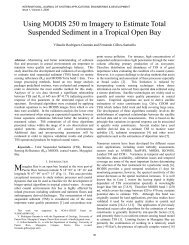
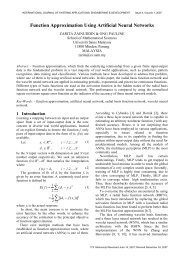
The block diagram of the proposed bio-<strong>inspired</strong> obstacle<br />
avoidance system is presented in Fig.4. The information<br />
received from the visual sensor is pre-processed in order to be<br />
successfully used in the proposed application, namely to guide<br />
visually impaired people. There are two types of redundant<br />
information, one comes from the obstacle detection function<br />
and the second comes from the application itself. The first one<br />
is eliminated using an edge detection algorithm in the preprocessed<br />
part, and the second by extracting from the entire<br />
visual field only the area of interest, which in this case is the<br />
walking path area. Next, after eliminating the redundant<br />
information, the result of the pre-processed data is distributed<br />
at three channels where is computed differently.In one<br />
channel, the extracted area is enlarged by both axes (zoomed<br />
area), while the others two channels leaves it unchanged. The<br />
EMD block compute the information received from the first<br />
two channels pixel by pixel. The summation of all pixels<br />
provided by the EMD’s output represents an excitation signal<br />
(e(t)) that shows the closeness or distance of an obstacle on the<br />
walking path, while the summation of all pixels from<br />
unchanged area of channel three (i(t)) represents an inhibition<br />
signal.The variation of the difference between the excitation<br />
and the inhibition signals contains the information about a<br />
possible collision with an obstacle. When the subject is<br />
approaching to an object, the difference between the excitation<br />
and the inhibition signal will increase, and this is captured by<br />
the window comparator if the lower threshold (VthL) and the<br />
upper threshold (VthH) are properly adjusted. One of the<br />
problem here is that the variation of the difference between the<br />
excitation and the inhibition signal ( e(t) – i(t) ) changes the<br />
mean value continuously according with the environmental<br />
light, so using fixed thresholds for the window comparator<br />
would lead to wrong decisions for the system. We improved<br />
this condition by extracting the mean value from the [e(t) –<br />
i(t)] signal and used it to generate the threshold for the<br />
window comparator. So, in this case the lower threshold for<br />
the window comparator is obtain from the sum between the<br />
mean value of the excitation and the inhibition signal<br />
difference, plus a threshold value, while the upper threshold<br />
for the window comparator is obtain from the difference<br />
between the mean value of the excitation and the inhibition<br />
signal difference minus a threshold value.
INTERNATIONAL JOURNAL OF SYSTEMS APPLICATIONS, ENGINEERING & DEVELOPMENT<br />
Issue 6, Volume 5, 2011<br />
Fig.4 <strong>Bio</strong>-inpired collision avoidance system<br />
concept<br />
IV. SIMULATION OF THE BIO-INSPIRED COLLISION<br />
AVOIDANCE SYSTEM<br />
For the simulation of the bio-<strong>inspired</strong> obstacle avoidance<br />
system we used situations that were recorded in a real<br />
environment. We used two examples in this paper, a recording<br />
made by a camera mounted on a subject that moves on an alley<br />
in the park and the second one, in which the subject moves in<br />
the parking area.<br />
In Fig.6 are recorded frames that were taken during the<br />
subject’s movement along the alley, while in Fig.5 are the<br />
705<br />
corresponding areas for the variation between the excitation<br />
and the inhibition signals, and also the impulses generated by<br />
the window comparator which signals an approach with an<br />
obstacle on the pathway. As can be seen in Fig.5, the average<br />
difference between the excitation and the inhibition signal is<br />
changing continuosly during the subject’s movement along the<br />
alley, so by doing the thresholds of the window comparator<br />
depend on this value we are able to detect more accurately the<br />
proximity of an obstacle. In the frame A from Fig.6, there are<br />
no obstacles so the output’s system will not generate any pulse.<br />
Next, the subject is approaching a hedge and the system starts<br />
to generate pulses (frame B), moment when the subject<br />
changes the walking direction and the system stops generating
INTERNATIONAL JOURNAL OF SYSTEMS APPLICATIONS, ENGINEERING & DEVELOPMENT<br />
Issue 6, Volume 5, 2011<br />
pulses because there are no obstacles in the vicinity (frame<br />
C).The subject continues to walk on the pathway and<br />
aproaches a new obstacle, in this case a concrete pillar (frame<br />
D),and the systems starts again to generate pulses. As<br />
continues to approach the pillar, the systems generate a longer<br />
train of pulses (frame E) indicating a frontal collision with the<br />
obstacle.<br />
In the second example (Fig.7 and Fig.8) the recorded frames<br />
were taken during the subject’s movement along the parking<br />
area. Initial, when the subject start walking, there are<br />
Fig.5 (1) The sum between the mean value of the excitation and the inhibition signal difference plus the<br />
upper threshold value:mean[ e(t)-i(t)] +VthH. (2) The difference between the excitation and the inhibition<br />
signal: e(t) – i(t). (3) The difference between the mean value of the excitation and the inhibition signal<br />
difference minus the lower threshold value:mean[ e(t)-i(t)] -VthL (4) Decision made by the window<br />
comparator: out(t).<br />
A B C D E<br />
Fig.6 Different frames recorded during the subject's movement along the alley<br />
706
INTERNATIONAL JOURNAL OF SYSTEMS APPLICATIONS, ENGINEERING & DEVELOPMENT<br />
Issue 6, Volume 5, 2011<br />
(1)<br />
(2)<br />
(3)<br />
(4)<br />
mean[e(t) – i(t)]+VthH<br />
e(t) – i(t)<br />
mean[e(t) – i(t)]-VthL<br />
out(t)<br />
Fig.7 (1) The sum between the mean value of the excitation and the inhibition signal difference plus the<br />
upper threshold value:mean[ e(t)-i(t)] +VthH. (2) The difference between the excitation and the inhibition<br />
signal:e(t) – i(t). (3) The difference between the mean value of the excitation and the inhibition signal<br />
difference minus the lower threshold value:mean[ e(t)-i(t)] -VthL (4) Decision made by the window<br />
comparator: out(t).<br />
Fig.8 Different frames recorded during the subject's movement along the parking area<br />
707
INTERNATIONAL JOURNAL OF SYSTEMS APPLICATIONS, ENGINEERING & DEVELOPMENT<br />
Issue 6, Volume 5, 2011<br />
no obstacles in front of him ( frame A) so the system doesn’t<br />
generate any pulse. Next, the subject changes the walking<br />
direction at the right side where is a stationary car (frame B)<br />
and the system starts to generate pulses. The subject is<br />
returning to the initial trajectory (frame C) so the systems stops<br />
generating pulses. In frame D is changing again the walking<br />
path direction and approaches another car from a different<br />
angle and the system generates again a train of pulses. When<br />
the subject returns again to the initial trajectory (frame E)<br />
encounters another person who is walking in front of him and<br />
also in this case the system recognize the person as an object<br />
that can collide with and respond with pulse generation. In the<br />
next frames (F, G, H, I, J) the procedure is repeated and the<br />
system responds accordingly.<br />
V. CONCLUSION<br />
In this paper we presented a bio-<strong>inspired</strong> obstacle avoidance<br />
system, in the idea of creating a device that could be<br />
implemented and used in the guidance of the visually impaired<br />
people. The main core of the system, the Elementary Motion<br />
Detector (Reichardt correlator) is <strong>inspired</strong> from the insect’s<br />
visual system. Based on previous researches and applications<br />
that exist in literature, we designed and simulated a system that<br />
was adapted to the desired purpose. The modifications made<br />
were in the pre- processing part by extracting only the area of<br />
interest from the entire visual field and by doing this, we<br />
manage to get better results in the function of the system and<br />
also increase the speed in data processing. The second<br />
improvement was made in the decision part by creating a<br />
dependency for the thresholds with the signal itself, resulting<br />
in a more accurate obstacle detection.<br />
We are looking forward to bring more improvements and to<br />
implement the entire system into a single chip, or by using an<br />
embedded system.<br />
REFERENCES<br />
[1] Sergi Bermudez i Badia, Paul F.M.J. Verschure A collision avoidance<br />
model based on the Lobula Giant Motion Detector (LGMD) Neuron of<br />
the Locust, Neural Networks, 2004. Proceedings. 2004 IEEE<br />
International Joint Conference; Vol.III, pp.1757-1761.<br />
[2] Sergi Bermudez i Badia, Pawel Pyk and Paul F.M.J. Verschure, A flylocust<br />
based neuronal control system applied to an unmanned aerial<br />
vehicle: the invertebrate neuronal principles for course stabilization,<br />
altitude control and collision avoidance, The International Journal of<br />
Robotics Research 2007, 26, 759-772.<br />
[3] M.E. Basch, D.G. Cristea, V. Tiponut, T. Slavici, Elaborated motion<br />
detector based on Hassenstein-Reichardt correlator model, LATEST<br />
TRENDS ON SYSTEMS 2010, Vol.I, pp. 192-195.<br />
[4] M.E. Basch, D.G. Cristea, R..I.Lorincz, A <strong>Bio</strong>-<strong>inspired</strong> Obstacle<br />
<strong>Avoidance</strong> <strong>System</strong> Concept for Visually Impaired People, Recent<br />
Researches in <strong>System</strong> Science, 15th WSEAS International Conference<br />
on SYSTEMS, 2011,pp.288-291<br />
[5] Patrick A. Shoemaker, David C. O’Carroll, Andrew D. Straw,<br />
Implementation of visual motion detection with contrast adaptation,<br />
Proceedings of SPIE,Vol.4951, pp.316-327.<br />
[6] V. Tiponut, D. Ianchis, M.E. Basch, Z. Haraszy, Work Directions and<br />
New Results in Electronic Travel Aids for Blind Visually Impaired<br />
708<br />
People, WSEAS TRANSACTIONS on SYSTEM, Issue 10, Volume 9<br />
,October 2010, pp.1086-1097.<br />
[7] V.Tiponut, A.Gacsadi, L.Tepelea, C.Lar, I.Gavrilut, Integrated<br />
Environment for Assisted Movement of Visually Impaired, Proceedings<br />
of the 15th International Workshop on Robotics in Alpe- Adria-Danube<br />
Region, (RAAD 2006), ISBN: 9637154 48 5, Balatonfured, Hungary,<br />
2006, pp. 234-239.<br />
[8] V. Tiponut, S. Popescu, I. Bogdanov, C. Caleanu, Obstacles Detection<br />
<strong>System</strong> for Visually Impaired Guidance, 12th WSEAS<br />
INTERNATIONAL CONFERENCE ON SYSTEMS, Heraklion,<br />
Greece, July 22-24, 2008,pp.350-354.<br />
[9] V. Tiponut, D. Ianchis, Z. Haraszy, Assisted Movement of Visually<br />
Impaired in Outdoor Environments –Work Directions and New Results,<br />
PROCEEDINGS OF THE 13th WSEAS INTERNATIONAL<br />
CONFERENCE ON SYSTEMS,2009,pp.386-391.<br />
[10] F. Claire Rind, Motion Detectors in the Locust Visual <strong>System</strong> - From<br />
<strong>Bio</strong>logy to Robot Sensors, MICROSCOPY RESEARCH AND<br />
TECHNIQUE, Vol.56,pp.256-269.<br />
[11] Alexander Borst, Drosophila’s View on Insect Vision, Elsevier Current<br />
<strong>Bio</strong>logy, Vol.XIX, 2009,pp.36-47.<br />
[12] John K. Douglass, Nicholas J. Strausfeld, Visual motion detection in<br />
flies: parralel direction and non-direction-sensitive pathways between<br />
the medulla and lobula plate, The Journal of Neuroscience, Vol.XV,<br />
pp.4551-4562.<br />
[13] Hausen, K. (1984). The lobula-complex of the fly: Structure, function<br />
and significance in visual behaviour. In Photoreception and Vision in<br />
Invertebrates, M.A. Ali, ed. (New York, London: Plenum Press), pp.<br />
523–559.<br />
[14] Scott, E.K., Raabe, T., and Luo, L. (2002). Structure of the vertical and<br />
horizontal system neurons of the lobula plate in Drosophila. J. Comp.<br />
Neurol. 454, 470–481.<br />
[15] Joesch, M., Plett, J., Borst, A., and Reiff, D.F. (2008). Response<br />
properties of motion-sensitive visual interneurons in the lobula plate of<br />
Drosophila melanogaster. Curr. <strong>Bio</strong>l. 18, 368–374.<br />
[16] Wehner, R., and Labhart, T. (2006). Polarisation vision. In Invertebrate<br />
Vision, E. Warrent and D.-E. Nilsson, eds. (Cambridge: Cambridge<br />
University Press), pp. 291–348.<br />
[17] Hardie, R.C. (1986) The photoreceptor array of the dipteran retina.<br />
Trends Neurosci. 9, 419–423.<br />
[18] Collet, T.S., and Land, M.F. (1975). Visual control of flight behavior in<br />
the hoverfly, Syritta pipiens L. J. Comp. Physiol. A 99, 1–66.<br />
[19] Reichardt, W., and Poggio, T. (1979). Figure-ground discrimination by<br />
relative movement in the visual system of the fly. Part I: Experimental<br />
results. <strong>Bio</strong>l. Cybern. 35, 81–100.<br />
[20] Egelhaaf, M. (1985). On the neuronal basis of figure-ground<br />
discrimination by relative motion in the visual system of the fly. I.<br />
Behavioural constraints imposed on the neuronal network and the role<br />
of the optomotor system. <strong>Bio</strong>l. Cybern. 52, 123–140.<br />
[21] Tammero, L.F., and Dickinson, M.H. (2002). The influence of visual<br />
landscape on the free flight behavior of the fruit fly Drosophila<br />
melanogaster. J. Exp. <strong>Bio</strong>l. 205, 327–343.<br />
[22] Heisenberg, M., and Wolf, R. (1984). Vision in Drosophila (Berlin,<br />
Heidelberg: Springer Press).<br />
[23] Mronz, M., and Lehmann, F.O. (2008). The free-flight response of<br />
Drosophila to motion of the visual environment. J. Exp. <strong>Bio</strong>l. 211,<br />
2026–2045.<br />
[24] Sherman, A., and Dickinson, M.H. (2002). A comparison of visual and<br />
haltere-mediated equilibrium refelxes in the fruit fly Drosophila<br />
melanogaster. J. Exp. <strong>Bio</strong>l. 206, pp.295–302.<br />
[25] Cook, T., and Desplan, C. (2001). Photoreceptor subtype specification:<br />
from flies to humans. Semin. Cell Dev. <strong>Bio</strong>l. 12, pp.509–518.<br />
[26] Kalmus, H. (1949). Optomotor responses in Drosophila and Musca.<br />
Physiologia comparata et oecologia 1/2,pp. 127–147.<br />
[27] Fischbach, K.F., and Heisenberg, M. (1981). Structural brain mutant of<br />
Drosophila melanogaster with reduced cell number in the medulla<br />
cortex and with normal optomotor yaw response. Proc. Natl. Acad. Sci.<br />
USA 78,pp.1105–1109.<br />
[28] Buchner, E., Buchner, S., and Bu¨ lthoff, I. (1984). Deoxyglucose<br />
mapping of nervous activity induced in Drosophila brain by visual<br />
movement. J. Comp. Physiol. A 155, pp.471–483.
INTERNATIONAL JOURNAL OF SYSTEMS APPLICATIONS, ENGINEERING & DEVELOPMENT<br />
Issue 6, Volume 5, 2011<br />
Mihai Emanuel Basch was born in Timisoara,<br />
Romania in 1982. He received the B. Sc. degree in<br />
2006 in electronics and telecommunication<br />
engineering from the Politehnica University of<br />
Timisoara, Romania. He is a PhD candidate from<br />
2009 in the field of Neuromorphic engineering in the Department of Applied<br />
Electronics of the Politehnica University of Timisoara, Romania.<br />
His current research includes bio<strong>inspired</strong> visual systems, microelectronics,<br />
electrochemistry, and biotechnology.<br />
Róbert István Lőrincz was born in Romania in 1981. He received the B. Sc.<br />
degree at Technical University of Cluj Napoca, department of Electronics and<br />
Telecommunication. He is a PhD candidate from 2008 in the field of<br />
automotive applied electronics at Politehnica University of Timisoara,<br />
Romania. His current research includes power electronics for automotive<br />
applications, microelectronics and neuromorphic engineering .<br />
David George Cristea was born in Vulcan,<br />
Romania, in 1983. He received the B. Sc. degree in<br />
2008 in electronics and telecommunication<br />
engineering and the M. Sc. degree in 2010 in<br />
electrical engineering from the Politehnica University<br />
of Timisoara, Romania. He is a PhD candidate from<br />
2008 in the field of electrochemical sensors,<br />
bioluminescent sensors and microelectronics in the<br />
Department of Applied Electronics of the Politehnica University of<br />
Timisoara, Romania.<br />
His current research includes microelectronics, electrochemistry, and<br />
biotechnology, universal signal conditioning circuits for electrochemical and<br />
bioluminescent sensors, spatial hearing, acoustic virtual reality, HRTF<br />
measurements and acoustical signal processing.<br />
Virgil Tiponut was born in Oradea, Romania ,in<br />
1942. He received the M.Sc. in 1968, in Electrical<br />
Engineering/Computer Science, and the Ph.D. degree<br />
in Electronic Engineering and Telecommunications,<br />
in 1981, both at the Politehnica University of<br />
Timisoara, Romania. Since graduation he is with<br />
Politehnica University of Timisoara and curently he<br />
is a professor at Electronic and Telecommunication Faculty, responsable for<br />
teaching in embedded systems, smart transducers and neural networks.<br />
His research interests include bio<strong>inspired</strong> systems, with application in mobile<br />
and rehabilitation robotics and some closed related areas: smart transducers,<br />
neural networks and fuzzy logic, biomedical engineering, embedded systems.<br />
He has published more than 100 papers in national and international Journals<br />
and Conference Proceedings, authored 10 books and 10 text books, and holds<br />
21 patents. He conducted more than 25 research and development projects,<br />
grants and contracts in the field of embedded systems, robotics and smart<br />
transducers.<br />
Dr. Tiponut is a member of the IEEE Society (CAS), WSEAS Society,<br />
member of the Society of Electronic Engineers from Romania, doctor Honoris<br />
Causa of University of Oradea and corresponding member of the Academy of<br />
Technical Science from Romania.<br />
Ivan Bogdanov was born in Timisoara, Romania,<br />
in 1952. He received the Ph.D degree in Electronic<br />
Engineering and Telecommunications in 1992.<br />
Curently he is a professor at the Electronic and<br />
Telecommunication Faculty from Politehnica<br />
University, Timsioara. Domain of interest : robotics,<br />
systems, numerical data processing , assembly<br />
language. He has more than 60 scientific papers and<br />
articles published , most representative being: „Microprocesorul în comanda<br />
acţionărilor electrice”, Ivan Bogdanov, Ed. „Facla” Timişoara, 1989, ISBN<br />
973-36-0030-x; „Conducerea cu calculatorul a acţionărilor electrice”, Ivan<br />
Bogdanov, Ed. „Orizonturi universitare”, Timişoara, 2004, ISBN 973 – 638-<br />
112-9; „Conducerea roboţilor”, Ivan Bogdanov, Ed. „Orizonturi<br />
universitare”, Timişoara, ian.2010.<br />
709