

FSB50450 Smart Power Module - Fairchild Semiconductor
FSB50450 Smart Power Module - Fairchild Semiconductor
FSB50450 Smart Power Module - Fairchild Semiconductor

Create successful ePaper yourself
Turn your PDF publications into a flip-book with our unique Google optimized e-Paper software.
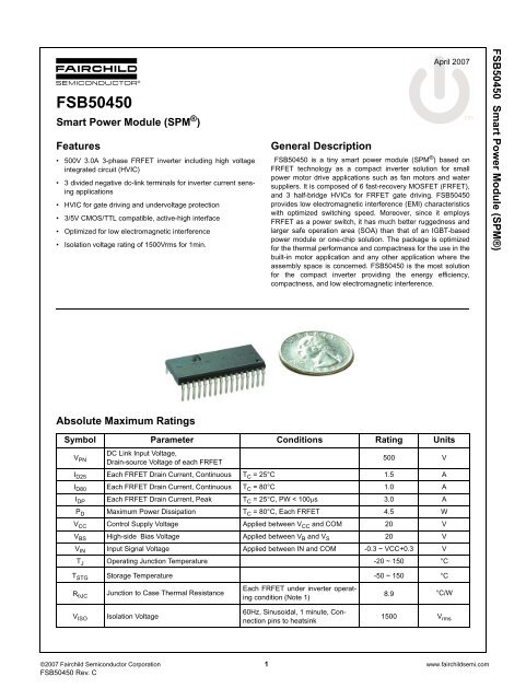
<strong>FSB50450</strong><br />
<strong>Smart</strong> <strong>Power</strong> <strong>Module</strong> (SPM ® )<br />
Features<br />
• 500V 3.0A 3-phase FRFET inverter including high voltage<br />
integrated circuit (HVIC)<br />
• 3 divided negative dc-link terminals for inverter current sensing<br />
applications<br />
• HVIC for gate driving and undervoltage protection<br />
• 3/5V CMOS/TTL compatible, active-high interface<br />
• Optimized for low electromagnetic interference<br />
• Isolation voltage rating of 1500Vrms for 1min.<br />
Absolute Maximum Ratings<br />
General Description<br />
April 2007<br />
<strong>FSB50450</strong> is a tiny smart power module (SPM ® ) based on<br />
FRFET technology as a compact inverter solution for small<br />
power motor drive applications such as fan motors and water<br />
suppliers. It is composed of 6 fast-recovery MOSFET (FRFET),<br />
and 3 half-bridge HVICs for FRFET gate driving. <strong>FSB50450</strong><br />
provides low electromagnetic interference (EMI) characteristics<br />
with optimized switching speed. Moreover, since it employs<br />
FRFET as a power switch, it has much better ruggedness and<br />
larger safe operation area (SOA) than that of an IGBT-based<br />
power module or one-chip solution. The package is optimized<br />
for the thermal performance and compactness for the use in the<br />
built-in motor application and any other application where the<br />
assembly space is concerned. <strong>FSB50450</strong> is the most solution<br />
for the compact inverter providing the energy efficiency,<br />
compactness, and low electromagnetic interference.<br />
Symbol Parameter Conditions Rating Units<br />
VPN DC Link Input Voltage,<br />
Drain-source Voltage of each FRFET<br />
500 V<br />
ID25 Each FRFET Drain Current, Continuous TC = 25°C 1.5 A<br />
ID80 Each FRFET Drain Current, Continuous TC = 80°C 1.0 A<br />
IDP Each FRFET Drain Current, Peak TC = 25°C, PW < 100μs 3.0 A<br />
PD Maximum <strong>Power</strong> Dissipation TC = 80°C, Each FRFET 4.5 W<br />
VCC Control Supply Voltage Applied between VCC and COM 20 V<br />
VBS High-side Bias Voltage Applied between VB and VS 20 V<br />
VIN Input Signal Voltage Applied between IN and COM -0.3 ~ VCC+0.3 V<br />
TJ Operating Junction Temperature -20 ~ 150 °C<br />
T STG Storage Temperature -50 ~ 150 °C<br />
R θJC<br />
V ISO<br />
Junction to Case Thermal Resistance<br />
Isolation Voltage<br />
Each FRFET under inverter operating<br />
condition (Note 1)<br />
60Hz, Sinusoidal, 1 minute, Connection<br />
pins to heatsink<br />
©2007 <strong>Fairchild</strong> <strong>Semiconductor</strong> Corporation 1 www.fairchildsemi.com<br />
<strong>FSB50450</strong> Rev. C<br />
8.9<br />
°C/W<br />
1500 V rms<br />
<strong>FSB50450</strong> <strong>Smart</strong> <strong>Power</strong> <strong>Module</strong> (SPM®)
Pin Descriptions<br />
Pin Number Pin Name Pin Description<br />
Note:<br />
Source terminal of each MOSFET is not connected to supply ground or bias voltage ground inside SPM ® . External connections should be made as indicated in Figure 2 and 5.<br />
Figure 1. Pin Configuration and Internal Block Diagram (Bottom View)<br />
<strong>FSB50450</strong> Rev. C<br />
1 COM IC Common Supply Ground<br />
2 V B(U) Bias Voltage for U Phase High Side FRFET Driving<br />
3 V CC(U) Bias Voltage for U Phase IC and Low Side FRFET Driving<br />
4 IN (UH) Signal Input for U Phase High-side<br />
5 IN (UL) Signal Input for U Phase Low-side<br />
6 V S(U) Bias Voltage Ground for U Phase High Side FRFET Driving<br />
7 V B(V) Bias Voltage for V Phase High Side FRFET Driving<br />
8 V CC(V) Bias Voltage for V Phase IC and Low Side FRFET Driving<br />
9 IN (VH) Signal Input for V Phase High-side<br />
10 IN (VL) Signal Input for V Phase Low-side<br />
11 V S(V) Bias Voltage Ground for V Phase High Side FRFET Driving<br />
12 V B(W) Bias Voltage for W Phase High Side FRFET Driving<br />
13 V CC(W) Bias Voltage for W Phase IC and Low Side FRFET Driving<br />
14 IN (WH) Signal Input for W Phase High-side<br />
15 IN (WL) Signal Input for W Phase Low-side<br />
16 V S(W) Bias Voltage Ground for W Phase High Side FRFET Driving<br />
17 P Positive DC–Link Input<br />
18 U Output for U Phase<br />
19 N U Negative DC–Link Input for U Phase<br />
20 N V Negative DC–Link Input for V Phase<br />
21 V Output for V Phase<br />
22 N W Negative DC–Link Input for W Phase<br />
23 W Output for W Phase<br />
(1) COM<br />
(2) VB(U) (3) VCC(U) (4) IN (UH)<br />
(5) IN (UL)<br />
(6) VS(U) (7) VB(V) (8) VCC(V) (9) IN (VH)<br />
(10) IN (VL)<br />
(11) VS(V) (12) VB(W) (13) VCC(W) (14) IN (WH)<br />
(15) IN (WL)<br />
(16) V S(W)<br />
VCC<br />
HIN<br />
LIN<br />
COM<br />
VCC<br />
HIN<br />
LIN<br />
COM<br />
VCC<br />
HIN<br />
LIN<br />
COM<br />
VB<br />
HO<br />
VS<br />
LO<br />
VB<br />
HO<br />
VS<br />
LO<br />
VB<br />
HO<br />
VS<br />
LO<br />
(17) P<br />
(18) U<br />
(19) N U<br />
(20) N V<br />
(21) V<br />
(22) N W<br />
(23) W<br />
2 www.fairchildsemi.com<br />
<strong>FSB50450</strong> <strong>Smart</strong> <strong>Power</strong> <strong>Module</strong> (SPM®)
Electrical Characteristics (T J = 25°C, V CC=V BS=15V Unless Otherwise Specified)<br />
Inverter Part (Each FRFET Unless Otherwise Specified)<br />
Symbol Parameter Conditions Min Typ Max Units<br />
Control Part (Each HVIC Unless Otherwise Specified)<br />
Note:<br />
BV DSS<br />
ΔBV DSS/<br />
ΔT J<br />
I DSS<br />
R DS(on)<br />
V SD<br />
1. For the measurement point of case temperature T C , please refer to Figure 3 in page 4.<br />
2. BVDSS is the absolute maximum voltage rating between drain and source terminal of each FRFET inside SPM ® . VPN should be sufficiently less than this value considering the<br />
effect of the stray inductance so that VDS should not exceed BVDSS in any case.<br />
3. tON and tOFF include the propagation delay time of the internal drive IC. Listed values are measured at the laboratory test condition, and they can be different according to the<br />
field applcations due to the effect of different printed circuit boards and wirings. Please see Figure 4 for the switching time definition with the switching test circuit of Figure 5.<br />
4. The peak current and voltage of each FRFET during the switching operation should be included in the safe operating area (SOA). Please see Figure 5 for the RBSOA test circuit<br />
that is same as the switching test circuit.<br />
Package Marking & Ordering Information<br />
<strong>FSB50450</strong> Rev. C<br />
Drain-Source Breakdown<br />
Voltage<br />
Breakdown Voltage Temperature<br />
Coefficient<br />
Zero Gate Voltage<br />
Drain Current<br />
Static Drain-Source<br />
On-Resistance<br />
Drain-Source Diode<br />
Forward Voltage<br />
V IN = 0V, I D = 250μA (Note 2) 500 - - V<br />
I D = 250μA, Referenced to 25°C - 0.53 - V<br />
V IN = 0V, V DS = 500V - - 250 μA<br />
V CC = V BS = 15V, V IN = 5V, I D = 1.0A - 1.9 2.4 Ω<br />
V CC = V BS = 15V, V IN = 0V, I D = -1.0A - - 1.2 V<br />
tON VPN = 300V, VCC = VBS = 15V, ID = 1.0A<br />
- 1152 - ns<br />
tOFF trr Switching Times<br />
VIN = 0V ↔ 5V, REH = 0Ω<br />
Inductive load L=3mH<br />
High- and low-side FRFET switching<br />
-<br />
-<br />
600<br />
185<br />
-<br />
-<br />
ns<br />
ns<br />
EON - 85 - μJ<br />
EOFF (Note 3)<br />
- 11 - μJ<br />
RBSOA<br />
Reverse-bias Safe Operating<br />
Area<br />
V PN = 400V, V CC = V BS = 15V, I D = I DP, R EH = 0Ω<br />
V DS =BV DSS , T J = 150°C<br />
High- and low-side FRFET switching (Note 4)<br />
Full Square<br />
Symbol Parameter Conditions Min Typ Max Units<br />
I QCC Quiescent V CC Current V CC=15V, V IN=0V Applied between V CC and COM - - 160 μA<br />
I QBS Quiescent V BS Current V BS=15V, V IN=0V Applied between V B and V S - - 100 μA<br />
UVCCD Low-side Undervoltage VCC Undervoltage Protection Detection Level 7.4 8.0 9.4 V<br />
UVCCR Protection (Figure 6) VCC Undervoltage Protection Reset Level 8.0 8.9 9.8 V<br />
UVBSD High-side Undervoltage VBS Undervoltage Protection Detection Level 7.4 8.0 9.4 V<br />
UVBSR Protection (Figure 7) VBS Undervoltage Protection Reset Level 8.0 8.9 9.8 V<br />
VIH ON Threshold Voltage Logic High Level<br />
3.0 - - V<br />
Applied between IN and COM<br />
VIL OFF Threshold Voltage Logic Low Level - - 0.8 V<br />
IIH VIN = 5V<br />
- 10 20 μA<br />
Input Bias Current<br />
Applied between IN and COM<br />
IIL VIN = 0V - - 2 μA<br />
Device Marking Device Package Reel Size Tape Width Quantity<br />
<strong>FSB50450</strong> <strong>FSB50450</strong> SPM23AA _ _ 15<br />
3 www.fairchildsemi.com<br />
<strong>FSB50450</strong> <strong>Smart</strong> <strong>Power</strong> <strong>Module</strong> (SPM®)
Recommended Operating Conditions<br />
Symbol Parameter Conditions<br />
Note:<br />
(1) It is recommended the bootstrap diode D 1 to have soft and fast recovery characteristics with 600-V rating<br />
(2) Parameters for bootsrap circuit elements are dependent on PWM algorithm. For 15 kHz of switching frequency, typical example of parameters is shown above.<br />
(3) RC coupling(R 5 and C 5 ) at each input (indicated as dotted lines) may be used to prevent improper input signal due to surge noise. Signal input of SPM ® is compatible with<br />
standard CMOS or LSTTL outptus.<br />
(4) Bold lines should be short and thick in PCB pattern to have small stray inductance of circuit, which results in the reduction of surge voltage. Bypass capacitors such as C 1 , C 2<br />
and C 3 should have good high-frequency characteristics to absorb high-frequency ripple current.<br />
Figure 2. Recommended CPU Interface and Bootstrap Circuit with Parameters<br />
Note:<br />
Attach the thermocouple on top of the heatsink-side of SPM ® (between SPM ® and heatsink if applied) to get the correct temperature measurement.<br />
Figure 3. Case Temperature Measurement<br />
<strong>FSB50450</strong> Rev. C<br />
Value<br />
Min. Typ. Max.<br />
V PN Supply Voltage Applied between P and N - 300 400 V<br />
V CC Control Supply Voltage Applied between V CC and COM 13.5 15 16.5 V<br />
V BS High-side Bias Voltage Applied between V B and V S 13.5 15 16.5 V<br />
VIN(ON) Input ON Threshold Voltage<br />
3.0 VCC V<br />
Applied between IN and COM<br />
VIN(OFF) Input OFF Threshold Voltage 0 0.6 V<br />
t dead<br />
Blanking Time for Preventing<br />
Arm-short<br />
Units<br />
V CC =V BS =13.5 ~ 16.5V, T J ≤ 150°C 1.0 - - μs<br />
f PWM PWM Switching Frequency T J ≤ 150°C - 15 - kHz<br />
T C Case Temperature T J ≤ 150°C -20 125 °C<br />
Micom<br />
15-V Line<br />
10μF<br />
R 5<br />
R 1<br />
These values depend on PWM<br />
control algorithm<br />
C 5<br />
C 2<br />
D 1<br />
C 1<br />
3.80 mm<br />
VCC<br />
HIN<br />
LIN<br />
COM<br />
VB<br />
HO<br />
VS<br />
LO<br />
R 2<br />
One-Leg Diagram of SPM<br />
* Example of bootstrap paramters:<br />
C 1 = C 2 = 1μF ceramic capacitor,<br />
R 1 = 56Ω, R 2 = 20Ω<br />
14.50 mm<br />
MOSFET<br />
P<br />
N<br />
Inverter<br />
Output<br />
R 3<br />
V DC<br />
C 3<br />
HIN LIN<br />
0 0<br />
0 1<br />
1 0<br />
1 1<br />
Open Open<br />
Case Temperature (T C )<br />
Detecting Point<br />
Output<br />
4 www.fairchildsemi.com<br />
Z<br />
0<br />
V DC<br />
Forbidden<br />
Z<br />
Note<br />
Both FRFET Off<br />
Low-side FRFET On<br />
High-side FRFET On<br />
Shoot-through<br />
Same as (0, 0)<br />
<strong>FSB50450</strong> <strong>Smart</strong> <strong>Power</strong> <strong>Module</strong> (SPM®)
<strong>FSB50450</strong> Rev. C<br />
V IN<br />
V DS<br />
I D<br />
V CC<br />
t ON<br />
100% of I D<br />
R BS<br />
I rr<br />
t rr<br />
120% of I D<br />
(a) Turn-on<br />
(b) Turn-off<br />
Figure 4. Switching Time Definition<br />
Figure 5. Switching and RBSOA(Single-pulse) Test Circuit (Low-side)<br />
Input Signal<br />
UV Protection<br />
Status<br />
Low-side Supply, V CC<br />
MOSFET Current<br />
Input Signal<br />
UV Protection<br />
Status<br />
High-side Supply, V BS<br />
MOSFET Current<br />
C BS<br />
VCC<br />
HIN<br />
LIN<br />
COM<br />
VB<br />
HO<br />
VS<br />
LO<br />
R EH<br />
Figure 6. Undervoltage Protection (Low-side)<br />
Figure 7. Undervoltage Protection (High-side)<br />
V IN<br />
I D<br />
V DS<br />
One-leg Diagram of SPM<br />
UV CCD<br />
t OFF<br />
UV CCR<br />
+<br />
VDS -<br />
10% of I D<br />
5 www.fairchildsemi.com<br />
I D<br />
L V DC<br />
RESET DETECTION RESET<br />
RESET DETECTION RESET<br />
UV BSD<br />
UV BSR<br />
<strong>FSB50450</strong> <strong>Smart</strong> <strong>Power</strong> <strong>Module</strong> (SPM®)
Micom<br />
<strong>FSB50450</strong> Rev. C<br />
R 1<br />
R 5<br />
R 1<br />
R 1<br />
C 5<br />
C 2<br />
C 2<br />
C 2<br />
15-V<br />
Supply<br />
C 1<br />
C 1<br />
C 1<br />
(1) COM<br />
(2) VB(U) (3) VCC(U) (4) IN (UH)<br />
(5) IN (UL)<br />
(6) VS(U) (7) VB(V) (8) VCC(V) (9) IN (VH)<br />
(10) IN (VL)<br />
(11) VS(V) (12) VB(W) (13) VCC(W) (14) IN (WH)<br />
(15) IN (WL)<br />
(16) V S(W)<br />
VCC<br />
HIN<br />
LIN<br />
COM<br />
VCC<br />
HIN<br />
LIN<br />
COM<br />
VCC<br />
HIN<br />
LIN<br />
COM<br />
VB<br />
HO<br />
VS<br />
LO<br />
VB<br />
HO<br />
VS<br />
LO<br />
VB<br />
HO<br />
VS<br />
LO<br />
R 2<br />
For 3-phase current sensing and protection<br />
(17) P<br />
(18) U<br />
(19) N U<br />
(20) N V<br />
(21) V<br />
(22) N W<br />
(23) W<br />
Figure 8. Example of Application Circuit<br />
C 4<br />
R 4<br />
R 3<br />
6 www.fairchildsemi.com<br />
M<br />
C 3<br />
V DC<br />
<strong>FSB50450</strong> <strong>Smart</strong> <strong>Power</strong> <strong>Module</strong> (SPM®)
Detailed Package Outline Drawings<br />
<strong>FSB50450</strong> Rev. C<br />
(1.165)<br />
#17<br />
#1<br />
2x3.90=7.80±0.30<br />
MAX 3.30<br />
(2.275)<br />
MAX 0.15<br />
13.34±0.30<br />
12.23±0.30<br />
15*1.778=26.67±0.30<br />
(0.30)<br />
0.60 ±0.10<br />
MAX1.00<br />
MAX1.00<br />
0.60 ±0.10<br />
(0.30)<br />
29.00±0.20<br />
1.95 ±0.30<br />
13.13±0.30<br />
4x3.90=15.60±0.30<br />
#16<br />
#23<br />
(1.30)<br />
12.0 ±0.20<br />
(1.80)<br />
(1.80)<br />
(1.00)<br />
14.00<br />
3.10±0.20<br />
8.10 ±0.20<br />
R0.40 R0.40<br />
7 www.fairchildsemi.com<br />
(3°~5°) (3°~5°)<br />
0.50 0.50 0.50 -0.05 -0.05 -0.05<br />
+0.10 +0.10 +0.10<br />
14.85±0.30<br />
<strong>FSB50450</strong> <strong>Smart</strong> <strong>Power</strong> <strong>Module</strong> (SPM®)
TRADEMARKS<br />
The following are registered and unregistered trademarks <strong>Fairchild</strong> <strong>Semiconductor</strong> owns or is authorized to use and is not intended to be an<br />
exhaustive list of all such trademarks.<br />
ACEx ®<br />
Across the board. Around the world.<br />
ActiveArray<br />
Bottomless<br />
Build it Now<br />
CoolFET<br />
CorePLUS<br />
CROSSVOLT<br />
CTL<br />
Current Transfer Logic<br />
DOME<br />
E 2 CMOS<br />
EcoSPARK ®<br />
EnSigna<br />
FACT Quiet Series<br />
FACT ®<br />
FAST ®<br />
FASTr<br />
FPS<br />
FRFET ®<br />
GlobalOptoisolator<br />
GTO<br />
HiSeC<br />
i-Lo<br />
ImpliedDisconnect<br />
IntelliMAX<br />
ISOPLANAR<br />
MICROCOUPLER<br />
MicroPak<br />
MICROWIRE<br />
Motion-SPM<br />
MSX<br />
MSXPro<br />
OCX<br />
OCXPro<br />
OPTOLOGIC ®<br />
OPTOPLANAR ®<br />
PACMAN<br />
PDP-SPM<br />
POP<br />
<strong>Power</strong>220 ®<br />
<strong>Power</strong>247 ®<br />
<strong>Power</strong>Edge<br />
<strong>Power</strong>Saver<br />
<strong>Power</strong>-SPM<br />
<strong>Power</strong>Trench ®<br />
Programmable Active Droop<br />
QFET ®<br />
QS<br />
QT Optoelectronics<br />
Quiet Series<br />
RapidConfigure<br />
RapidConnect<br />
ScalarPump<br />
SMART START<br />
SPM ®<br />
STEALTH<br />
SuperFET<br />
SuperSOT-3<br />
SuperSOT-6<br />
SuperSOT-8<br />
SyncFET<br />
TCM<br />
The <strong>Power</strong> Franchise ®<br />
<br />
TinyBoost<br />
TinyBuck<br />
TinyLogic ®<br />
TINYOPTO<br />
Tiny<strong>Power</strong><br />
TinyWire<br />
TruTranslation<br />
μSerDes<br />
UHC ®<br />
UniFET<br />
VCX<br />
Wire<br />
DISCLAIMER<br />
FAIRCHILD SEMICONDUCTOR RESERVES THE RIGHT TO MAKE CHANGES WITHOUT FURTHER NOTICE TO ANY PRODUCTS<br />
HEREIN TO IMPROVE RELIABILITY, FUNCTION, OR DESIGN. FAIRCHILD DOES NOT ASSUME ANY LIABILITY ARISING OUT OF THE<br />
APPLICATION OR USE OF ANY PRODUCT OR CIRCUIT DESCRIBED HEREIN; NEITHER DOES IT CONVEY ANY LICENSE UNDER ITS<br />
PATENT RIGHTS, NOR THE RIGHTS OF OTHERS. THESE SPECIFICATIONS DO NOT EXPAND THE TERMS OF FAIRCHILD’S<br />
WORLDWIDE TERMS AND CONDITIONS, SPECIFICALLY THE WARRANTY THEREIN, WHICH COVERS THESE PRODUCTS.<br />
LIFE SUPPORT POLICY<br />
FAIRCHILD’S PRODUCTS ARE NOT AUTHORIZED FOR USE AS CRITICAL COMPONENTS IN LIFE SUPPORT DEVICES OR<br />
SYSTEMS WITHOUT THE EXPRESS WRITTEN APPROVAL OF FAIRCHILD SEMICONDUCTOR CORPORATION.<br />
As used herein:<br />
1. Life support devices or systems are devices or systems<br />
which, (a) are intended for surgical implant into the body or<br />
(b) support or sustain life, and (c) whose failure to perform<br />
when properly used in accordance with instructions for use<br />
provided in the labeling, can be reasonably expected to<br />
result in a significant injury of the user.<br />
2. A critical component in any component of a life support,<br />
device, or system whose failure to perform can be<br />
reasonably expected to cause the failure of the life support<br />
device or system, or to affect its safety or effectiveness.<br />
PRODUCT STATUS DEFINITIONS<br />
Definition of Terms<br />
Datasheet Identification Product Status Definition<br />
Advance Information Formative or In Design This datasheet contains the design specifications for product<br />
development. Specifications may change in any manner without notice.<br />
Preliminary First Production This datasheet contains preliminary data; supplementary data will be<br />
published at a later date. <strong>Fairchild</strong> <strong>Semiconductor</strong> reserves the right to<br />
make changes at any time without notice to improve design.<br />
No Identification Needed Full Production This datasheet contains final specifications. <strong>Fairchild</strong> <strong>Semiconductor</strong><br />
reserves the right to make changes at any time without notice to improve<br />
design.<br />
Obsolete Not In Production This datasheet contains specifications on a product that has been<br />
discontinued by <strong>Fairchild</strong> <strong>Semiconductor</strong>. The datasheet is printed for<br />
reference information only.<br />
Rev. I27<br />
© 2007 <strong>Fairchild</strong> <strong>Semiconductor</strong> Corporation www.fairchildsemi.com


